IBM x3850 X6 Planning And Implementation Manual
Hide thumbs
Also See for x3850 X6:
- Installation and service manual (1730 pages) ,
- Product manual (52 pages) ,
- Installation instructions manual (26 pages)
Table of Contents
Advertisement
Quick Links
Advertisement
Table of Contents
Troubleshooting

Related Manuals for IBM x3850 X6


Summary of Contents for IBM x3850 X6
-
Page 1: Front Cover
Front cover IBM System x3850 X6 and x3950 X6 Planning and Implementation Guide Covers the sixth generation Enterprise X-Architecture servers Provides technical information about all server features Explains what planning you need to do David Watts Rani Doughty Ilya Solovyev... - Page 3 International Technical Support Organization IBM System x3850 X6 and x3950 X6 Planning and Implementation Guide September 2014 SG24-8208-00...
- Page 4 First Edition (September 2014) This edition applies to IBM System x3850 X6 and x3950 X6, machine type 3837, with Intel Xeon Processor E7-4800 v2 and Intel Xeon Processor E7-8800 v2 processors. © Copyright International Business Machines Corporation 2014. All rights reserved.
-
Page 5: Table Of Contents
2.4.5 IBM Advanced Page Retire........ - Page 6 2.6.4 IBM High IOPS adapters..........41 2.6.5 IBM FlashCache Storage Accelerator........42 2.7 UEFI .
- Page 7 3.22 Power subsystem ........... 101 3.23 Fans and cooling .
- Page 8 5.8.5 IBM Electronic Service Agent ........
-
Page 9: Notices
IBM representative for information on the products and services currently available in your area. Any reference to an IBM product, program, or service is not intended to state or imply that only that IBM product, program, or service may be used. Any functionally equivalent product, program, or service that does not infringe any IBM intellectual property right may be used instead. -
Page 10: Trademarks
IBM at the time this information was published. Such trademarks may also be registered or common law trademarks in other countries. A current list of IBM trademarks is available on the Web at http://www.ibm.com/legal/copytrade.shtml... -
Page 11: Summary Of Changes
Added Intel I350 Ethernet adapters Changed information: Certain processors do not support eXFlash DIMMs The eXFlash DIMM driver does not support RAID VMware vSphere 5.1 supports a maximum of 160 concurrent threads © Copyright IBM Corp. 2014. All rights reserved. - Page 12 IBM System x3850 X6 and x3950 X6 Planning and Implementation Guide...
-
Page 13: Preface
This book is aimed at clients, IBM Business Partners, and IBM employees that want to understand the features and capabilities of the IBM X6 portfolio of servers and want to learn how to install and configure the servers for use in production. -
Page 14: Authors
IBM System x marketing: Jacqueline Gutierrez Kyle Hampton Kathy Holomon Randy Lundin Iliyas Pathan Steve Simmons Randi Wood IBM System x development: David Brenchley David Fritz Josh Lowry Nina Newton IBM System x3850 X6 and x3950 X6 Planning and Implementation Guide... -
Page 15: Now You Can Become A Published Author, Too
Your comments are important to us! We want our books to be as helpful as possible. Send us your comments about this book or other IBM Redbooks publications in one of the following ways: Use the online Contact us review Redbooks form found at: ibm.com/redbooks... -
Page 16: Stay Connected To Ibm Redbooks
Look for us on LinkedIn: http://www.linkedin.com/groups?home=&gid=2130806 Explore new Redbooks publications, residencies, and workshops with the IBM Redbooks weekly newsletter: https://www.redbooks.ibm.com/Redbooks.nsf/subscribe?OpenForm Stay current on recent Redbooks publications with RSS Feeds: http://www.redbooks.ibm.com/rss.html IBM System x3850 X6 and x3950 X6 Planning and Implementation Guide... -
Page 17: Chapter 1. Introduction
IBM System x3850 x6, a four-socket 4U rack-mount server IBM System x3950 X6, an eight-socket 8U rack-mount server These servers are the sixth generation of servers built upon the IBM Enterprise X-Architecture. Enterprise X-Architecture is the culmination of bringing generations of IBM technology and innovation derived from our experience in high-end enterprise servers. -
Page 18: Target Workloads
They are designed for mission-critical, scalable workloads, including large databases, and ERP/CRM systems to support online transaction processing, business analytics, virtualization, and enterprise applications. This section describes how IBM X6 technology helps to address challenges clients are facing in these mission-critical enterprise environments. 1.1.1 Databases... -
Page 19: Business Analytics
Slow query execution and response times, which delay business decision making. Dramatic growth in data, which requires deeper analysis. IBM X6 systems can help to make businesses more agile and analytics-driven by providing up-to-the-minute analytics based on real-time data. As with OLTP workloads, in-memory databases or flash storage are used for workload optimization (see 1.4, “Storage versus... -
Page 20: Enterprise Applications: Erp And Crm
I/O load and increased performance in primary storage. For more information about FlashCache Accelerator see 1.5, “Flash storage” on page 8. IBM X6 support for an integrated hypervisor: All x3850 X6 and x3950 X6 models support the addition of an internal USB key with VMware ESXi installed. -
Page 21: Key Features
1.2 Key features The IBM X6 system is fast, agile, and resilient and makes meeting the business needs of your enterprise easier: Fast application performance means immediate access to actionable information. IBM X6 delivers fast application performance, thanks to an innovative scalable design and new storage technology that is designed to optimize overall solution performance. -
Page 22: Positioning
1.3 Positioning The IBM System x3850 X6 and x3950 X6 servers are the next generation of X-Architecture following on from the highly successful eX5 server. IBM X6 servers include a number of new features when compared to the previous generation of eX5 including support for more memory and I/O in a modular design. -
Page 23: Storage Versus In-Memory Data
Maximum configurations x3750 M4 x3850/x3950 X5 x3850/x3950 X6 Memory 1-node 48 DIMM slots 64 DIMM slots 96 DIMM slots 1-node with Not available 96 DIMM slots Not available MAX5 2-node Not available 128 DIMM slots 192 DIMM slots 2.5-inch drive 1-node bays 2-node... -
Page 24: Flash Storage
IBM eXFlash memory-channel storage: IBM eXFlash DIMMs represent innovative technology that utilizes DDR3 memory channels to connect flash storage modules. IBM is the first company that will deploy memory-channel storage technology in their industry-standard servers. These are key features of eXFlash DIMMs: –... -
Page 25: Energy Efficiency
2.6.2, “IBM eXFlash memory-channel storage” on page 38 2.6.5, “IBM FlashCache Storage Accelerator” on page 42 1.6 Energy efficiency The x3850 X6 and x3950 X6 offer the following energy-efficiency features to save energy, reduce operational costs, increase energy availability, and contribute to the green environment: Energy-efficient electronic components help lower operational costs. -
Page 26: Services Offerings
1.7 Services offerings The X6 systems fit into the services offerings that are already available from IBM Global Technology Services® for System x and BladeCenter. More information about these services is available at the following website: http://www.ibm.com/systems/services/gts/systemxbcis.html In addition to the existing offerings for asset management, information infrastructure, service management, security, virtualization, and consolidation, and business and collaborative solutions;... -
Page 27: Chapter 2. Technology
Technology Chapter 2. In this chapter, we give an overview of the technologies that IBM includes in the IBM System x3850 X6 and x3950 X6 servers. We describe system architecture and new chassis design with modular structure and the latest Intel Xeon E7-4800 v2 and E7-8800 v2 processors. -
Page 28: Modular Design
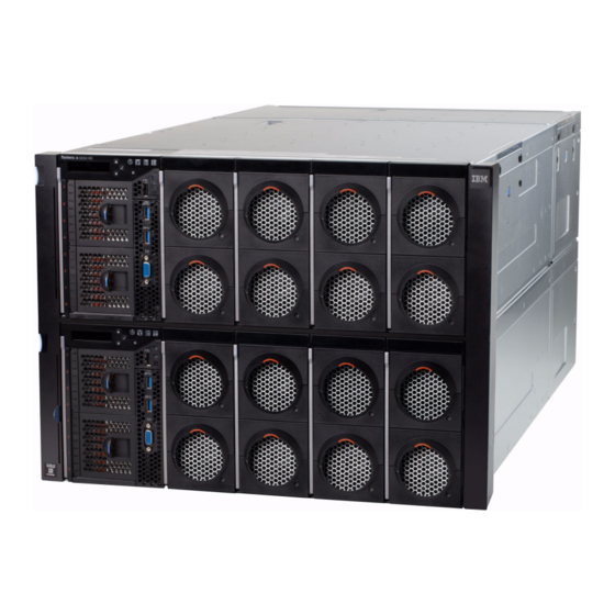
Figure 2-1 shows the IBM System x3850 X6. Figure 2-1 IBM System x3850 X6 The x3950 X6 looks like two x3850 X6 servers where one is placed on top of the other. However, unlike eX5 servers, x3950 X6 employs a single chassis with a single midplane design without any external connectors and cables. - Page 29 Figure 2-3 shows the x3850 X6 server with one of the four Compute Books partially removed. Figure 2-3 IBM x3850 X6 server with a Compute Book partially removed...
-
Page 30: Compute Books
– Half-length I/O Book. This hot-swap book provides three optional half-length PCIe slots. The x3850 X6 has one Primary I/O Book and supports one or two of the full or half-length I/O Books (one of each or two of either). The x3950 X6 has two Primary I/O Books and supports up to four of the full or half-length I/O Books (any combination). - Page 31 Figure 2-7 The Compute Book The x3850 X6 server supports up to four Compute Books; the x3950 X6 server supports up to 8 Compute Books. For more information about the Compute Books, see 3.6, “Compute Book” on page 64.
-
Page 32: Storage Book
Storage Book. Figure 2-8 The Storage Book The x3850 X6 server has one Storage Book; the x3950 X6 has two Storage Books. For more information about the Storage Book, see 3.10.1, “Storage Book” on page 75. 2.1.3 Primary I/O Book... -
Page 33: Additional I/O Books
The black air baffle is raised to show internal components. Figure 2-9 The Primary I/O Book internals The x3850 X6 has one Primary I/O Book. The x3950 X6 has two Primary I/O Books. For more information about the Primary I/O Book, see 3.12, “Primary I/O Book” on page 85. -
Page 34: Power Supplies
Half-length I/O Book Figure 2-10 Additional I/O Books The x3850 X6 server supports up to two additional I/O Books of any type; the x3950 X6 server supports up to four additional I/O Books. For more information about the additional I/O Books, see 3.13.1, “Half-length I/O Book” on page 89 and 3.13.2, “Full-length I/O Book”... -
Page 35: System Architecture
For more information about the additional power supplies, see 3.22, “Power subsystem” on page 101. 2.2 System architecture This section shows the overall architecture of both the x3850 X6 and x3950 X6. 2.2.1 x3850 X6 Figure 2-12 shows the system architecture of the x3850 X6 server. - Page 36 CPU 3 and CPU 4. If you need to install additional I/O Books, you should install the Compute Book in an appropriate slot first. The System x3850 X6 server is designed so that it can tolerate the failure of CPU 1. This feature decreases downtime in the event of a processor failure, and it requires two Compute Books installed in Compute Book slots 1 and 2, and an OS boot path from the CPU in Compute Book 2.
-
Page 37: X3950 X6
If you want to take advantage of this recovery, it is important to carefully plan your network and storage connectivity, because if CPU 1 fails, PCIe slots 9, 10, and 12 become unavailable. 2.2.2 x3950 X6 The x3950 X6 server has the same architecture adapted to 8-socket configuration. Figure 2-14 and Figure 2-15 show the system architecture of the x3950 X6 server (Figure 2-15 shows the upper half, and Figure 2-14 shows the lower half). - Page 38 E7 family. Figure 2-16 shows how the processors are connected together using QPI links. x3950 X6 - 8 sockets Figure 2-16 QPI connectivity - x3950 X6 with 8 processors installed IBM System x3850 X6 and x3950 X6 Planning and Implementation Guide...
-
Page 39: Processors
In addition, the 8-socket server has ability to form two independent systems containing four socket in each node, such as two independent x3850 X6 servers in one 8U chassis. This partitioning feature is enabled using the IMM2 interface. While partitioning is enabled, each partition can deploy its own operating system. -
Page 40: Intel Xeon Processor E7-4800/8800 V2 Product Family
There are two groups of the Intel Xeon processor E7 family that are used in the X6 servers and support scaling to separate levels: The Intel Xeon processor E7-4800 v2 product family is used in the x3850 X6. This family supports four-processor configurations. - Page 41 The new Intel Xeon processors feature advanced technologies described next. Intel Advanced Encryption Standard - New Instructions Advanced Encryption Standard (AES) is an encryption standard that is widely used to protect network traffic and sensitive data. Advanced Encryption Standard - New Instructions (AES-NI), available with the E7 processors, implements certain complex and performance intensive steps of the AES algorithm by using processor hardware.
- Page 42 Figure 2-19 shows the QPI configurations. On the left is how the four sockets of the x3850 X6 are connected together. On the right is how all eight sockets of the x3950 X6 are connected together.
- Page 43 Each processor has some amount of memory, connected directly to the processor. To access memory connected to another processor, each processor uses QPI links through another processors. This design creates a non-uniform memory access (NUMA) system. Similarly, I/O can be local to a processor or remote through another processor. For QPI use, Intel modified the MESI cache coherence protocol to include a forwarding state.
- Page 44 It keeps generated random numbers out of sight of malware and therefore enhances encryption protection. For more information, read the following Intel White Paper: http://www.intel.com/content/dam/www/public/us/en/documents/white-papers/3rd-gen-c ore-vpro-security-paper.pdf IBM System x3850 X6 and x3950 X6 Planning and Implementation Guide...
-
Page 45: Compute Books
2.3.2 Compute Books The core modular element of the X6 design is a Compute Book. It contains the following components: One Intel Xeon processor E7-4800 v2/8800 v2 product families processor 24 memory DIMM slots Two dual-motor fans Figure 2-20 shows the Compute Book. Compute book with the side cover attached Figure 2-20 The Compute Book... -
Page 46: Memory
12 DIMM modules Figure 2-22 The Compute Book’s right side The x3850 X6 supports up to four Compute Books, and the x3950 X6 supports up to eight Compute Books. Supported configurations include these: 1, 2, or 4 Compute Books for the x3850 X6 2, 4, or 8 Compute Books for the x3950 X6 All Compute Books in a server must have the same processors. -
Page 47: Operational Modes
Figure 2-23 shows the processor’s memory architecture. Intel Xeon processor Memory Memory controller controller SMI2 links Memory Memory Memory Memory buffer buffer buffer buffer DDR3 links DIMM DIMM DIMM DIMM DIMM DIMM DIMM DIMM DIMM DIMM DIMM DIMM DIMM DIMM DIMM DIMM DIMM... - Page 48 667 MHz 1333 MT/s 64 bit 10.7 GB/s RAS mode SMI2 Bus 800 MHz 1600 MT/s 64 bit 12.8 GB/s DDR3 Bus 800 MHz 1600 MT/s 64 bit 12.8 GB/s IBM System x3850 X6 and x3950 X6 Planning and Implementation Guide...
-
Page 49: Memory Mirroring And Rank Sparing
2.4.2 Memory mirroring and rank sparing In addition to Performance and RAS modes, the memory subsystem has additional reliability, availability, and serviceability (RAS) features that can be enabled from the Unified Extensible Firmware Interface (UEFI): Memory mirroring Rank sparing Memory mirroring To improve memory reliability and availability, the memory controller can mirror memory data to two memory channels. -
Page 50: Rank Sparing
In contrast to mirroring, sparing leaves more memory for the operating system. In sparing mode, the trigger for failover is a preset threshold of correctable errors. IBM System x3850 X6 and x3950 X6 Planning and Implementation Guide... - Page 51 When this threshold is reached, the content is copied to its spare rank. The failed rank is then taken offline, and the spare counterpart is activated for use. In rank sparing mode, one rank per memory channel is configured as a spare. The spare rank must have identical or larger memory capacity than all the other ranks (sparing source ranks) on the same channel.
-
Page 52: Chipkill
DIMM, additional single bit errors will result in PFA and light path diagnostics alerts. 2.4.5 IBM Advanced Page Retire Advanced Page Retire is an IBM unique algorithm to handle memory errors. It is a built-in sophisticated error handling firmware that leverages and co-ordinates memory recovery features, balancing the goals of maximum up time and minimum repair actions. -
Page 53: Pcie 3.0
Failed DIMMs are indicated by light path diagnostics LEDs physically at the socket location. IBM performs thorough testing to verify the features and co-ordination between the firmware and the operating system or hypervisor. -
Page 54: Internal Storage
2.6.5, “IBM FlashCache Storage Accelerator” on page 42 2.6.1 Storage Book The x3850 X6 and x3950 X6 servers support 1.8-inch solid-state drives (SSDs) in the IBM eXFlash SSD units and 2.5-inch SSDs and HDDs. The drives are installed in the Storage... - Page 55 Figure 2-28 shows an IBM eXFlash DIMM. Figure 2-28 IBM eXFlash DIMM The IBM eXFlash DIMM modules are installed into DDR3 slots and use memory channels of the processors. Data transfers between processors and eXFlash DIMMs run directly without any additional controllers such as PCIe controllers and SAS/SATA controllers. This approach allows you to significantly reduce latency and improve performance.
-
Page 56: Ibm Exflash Ssd Technology
Provides ultrahigh overall performance using array of eXFlash DIMMs in a parallel manner. Offers up to 12.8 TB total flash storage capacity per server with IBM 200 GB and 400 GB eXFlash DIMMs. Ultra low latency means less than 5 µs write latency. -
Page 57: Ibm High Iops Adapters
2.5-inch SAS hard disk drive bays. You can install the following number of eXFlash units: The x3850 X6 can have up to 16x 1.8-inch SSDs with up to two eXFlash units (up to eight SSDs per eXFlash unit). -
Page 58: Ibm Flashcache Storage Accelerator
Figure 2-31 shows the IBM 2.4TB High IOPS MLC Duo Adapter: Figure 2-31 IBM 2.4TB High IOPS MLC Duo Adapter For more information about IBM High IOPS Adapters, see the IBM Redbooks Product Guides: IBM Flash Adapters Enterprise Value for System x http://www.redbooks.ibm.com/abstracts/tips1089.html?Open... - Page 59 Files Disks Volumes Primary data storage Figure 2-32 IBM FlashCache Storage Accelerator deployment The FlashCache Storage Accelerator also works in virtualized environment, transparently caching data of virtual machines. Figure 2-33 shows the typical FlashCache deployment scenario for virtual environment. Application...
-
Page 60: Uefi
There are no beep codes; all errors are covered by light path diagnostics. There are human readable Event logs in F1 Setup. UEFI Settings can be accessed Out of Band via the IBM Advanced Setup Utility (ASU) through the IMM web interface. -
Page 61: Scalability
I/O capabilities just by adding additional Compute Books and I/O Books. You can build your initial configuration of an x3850 X6 server just with one Compute Book, one Primary I/O Book, and one Storage Book, and ultimately be able to reuse these components in an 8U x3950 X6 server consisting of eight Compute Books, two primary I/O Books, four additional I/O Books, and two Storage Books. - Page 62 X6 systems, all interconnects are integrated in the midplane. If you want to upgrade your existing 4-socket x3850 X6 to an 8-socket x3950 X6 and keep your existing serial number, IBM plans to have a service offering whereby a service engineer will come onsite with the new mechanical chassis, perform the field upgrade by transferring all components to the new chassis, and transfer the serial number to the new system.
-
Page 63: Chapter 3. Product Information
Product information Chapter 3. In this chapter, we describe the details of the components in the IBM System x3850 X6 and the IBM System x3950 X6. This chapter contains the following topics: 3.1, “Product features” on page 48 3.2, “Specifications” on page 51 3.3, “Standard models of X6 servers”... -
Page 64: Product Features
Based on the Intel Xeon processor E7-4800 v2 and E7-8800 v2 product family, x3850 X6 provides the following capabilities: – x3850 X6 supports up to four E7-4800 v2 processors with 60 cores and 120 threads, to maximize the concurrent execution of multi-threaded applications. -
Page 65: Agile System Design
Internal storage bays provide a flexible and scalable all-in-one platform to meet your increasing demands: – x3850 X6: Up to 16x 1.8-inch eXFlash SSD bays, or eight 2.5-inch bays – x3950 X6: Up to 32x 1.8-inch eXFlash SSD bays, or 16x 2.5-inch bays Offers up to 11 PCIe slots plus a dedicated Mezzanine LOM (ML2) adapter slot;... -
Page 66: Resilient Platform
Two integrated Trusted Platform Modules (TPMs) 1.2 support enables advanced cryptographic functionality, such as digital signatures and remote attestation. Industry-standard Advanced Encryption Standard (AES) NI provide support for faster, stronger encryption. IBM System x3850 X6 and x3950 X6 Planning and Implementation Guide... -
Page 67: Specifications
X6: 8U rack Processor x3850 X6: Up to four Intel Xeon E7-4800 v2 or E7-8800 v2 processors, each in a Compute Book. Each processor has either 15 cores (up to 2.8 GHz), 12 cores (up to 2.6 GHz), 10 cores (up to 2.2 GHz), eight cores (up to 2.0 GHz), or six cores (up to 3.4 GHz). - Page 68 GbE cards with RJ-45 connectors. x3950 X6 has two ML2 slots. Dedicated 1 GbE port for systems management. PCI Expansion slots x3850 X6: Up to 11 PCIe slots plus one dedicated Mezzanine LOM slot (12 total). The slots are as follows: Two PCIe 3.0 x8 slots for internal RAID controllers (Storage Book) Two PCIe 3.0 x16 slots (x16-wired), half-length, full-height (Primary I/O Book)
- Page 69 Documentation CD that contains the Installation and User's Guide Figure 3-1 shows the components of the cable management bracket kit that ship with the x3850 X6. A second set (ie two left and two right) are also shipped with the x3950 X6. Left cable...
-
Page 70: Standard Models Of X6 Servers
Model B3x includes the Broadcom NetXtreme II ML2 Dual Port 10GbE SFP+ adapter (BCM57810S based). All other models include Intel I350-T4 ML2 Quad Port GbE Adapter adapter (I350-AM4 based). SAP HANA models also include two Mellanox ConnectX-3 40GbE / FDR IB VPI Adapters (00D9550). IBM System x3850 X6 and x3950 X6 Planning and Implementation Guide... - Page 71 c. Models with 6 slots have the Primary I/O Book (4 slots) and Storage Book (2 slots) standard. Models with 9 slots also include one Half-length I/O Book. Models with 12 slots include two Half-length I/O Books. d. These models include DIMMs that are rated at 1600 MHz, but operate at up to 1333 MHz, as noted, to match the processor memory speed.
-
Page 72: Physical Design
Compute Books minimum), and one Storage Book, which can have up to 8 2.5-inch drives or up to 16 1.8-inch SSD drives. The x3850 X6 server also has 3 USB 3.0 ports from the front side, one video port, and the control panel with LCD screen. - Page 73 Figure 3-3 Front view of the x3950 X6 As shown in Figure 3-3, the x3950 X6 is the equivalent of two x3850 X6 servers. It can have up to eight Compute Books (four Compute Books minimum), and two Storage Books, each of which can have up to 8 2.5-inch drives or up to 16 1.8-inch SSD drives.
-
Page 74: Ports And Controls
Figure 3-5 Rear view of the x3950 X6 3.5 Ports and controls The x3850 X6 and x3950 X6 servers have a broad set of I/O ports and controls including an LCD system information display panel located on the front operator panel. In this section, we give a detailed description of ports, controls, and LEDs located on the X6 server. - Page 75 Figure 3-6 shows ports, controls, and LEDs on the front operator panel. Power Locate Check Storage book Scroll up Select button\ button\ log LED button button System error LED Reset button PCIe slot 11 Scroll down error LED button PCIe slot 12 USB 2.0 error LED connector...
-
Page 76: Lcd System Information Panel
Scroll down button: Press this button to scroll down or scroll to the right in the main menu to location and select the system information that you want displayed. IBM System x3850 X6 and x3950 X6 Planning and Implementation Guide... - Page 77 This shows a system supporting four Ethernet ports. If the numbers are flashing, the ports System name Network icon are active IBM x3850 X6 SYSTEM ON UEFI\POST code System status Check-mark above 2 indicates system is booting from alternative UEFI bank.
-
Page 78: Rear Ports And Leds
System error LED I/O board Serial port USB 2.0 Systems VGA video connectors management error LED connector 3V battery ethernet port error LED Figure 3-10 Rear ports and LEDs IBM System x3850 X6 and x3950 X6 Planning and Implementation Guide... - Page 79 Locate LED: Use this LED to visually locate the server among other servers. You can use IBM Systems Director to light this LED remotely. IMM can also be used to turn this LED on and off. This LED is functionally equivalent to the locate LED on the front of the server.
-
Page 80: Compute Book
The processor options are pre-installed in a Compute Book. See 3.7, “Processor options” on page 67. 3.6.1 Compute Book design The main component of x3850 X6 and x3950 X6 servers is the Compute Book. It contains the following components: One Intel Xeon E7-4800 v2 or E7-8800 v2 processor... - Page 81 The internals of the Compute Book are shown in Figure 3-12. The system board of the Compute Book has two sides on which all components reside. 12x DIMM slots on Two hot-swap right side of the dual-motor fans Compute Book 12x DIMM slots on left side of the Compute Book...
-
Page 82: Compute Book Population Order
3837-A4x. No other server model or CTO configuration supports one processor. The x3950 X6 supports these combinations: 4 Compute Books 6 Compute Books 8 Compute Books Other combinations are not supported. IBM System x3850 X6 and x3950 X6 Planning and Implementation Guide... -
Page 83: Processor Options
8 Compute Books - All bays 3.7 Processor options The x3850 X6 and x3950 X6 servers use the Intel Xeon E7-4800 v2 or E7-8800 v2 processor, formerly known by the code name “IvyBridge-EX”. The Intel Xeon E7-4800 v2 series processors is available with up to 15 cores and 37.5 MB of last-level cache, and can form a 4-socket configuration. - Page 84 Performance mode (also known as independent mode). In Performance mode, the SMI2 link operates at twice the memory bus speed shown. c. A configuration of one processor is only supported in model 3837-A4x. No other server model or CTO configuration supports one processor. IBM System x3850 X6 and x3950 X6 Planning and Implementation Guide...
-
Page 85: Memory
IBM memory automatically assumes the IBM system warranty, and IBM provides service and support worldwide. As introduced in 2.4, “Memory” on page 30, the x3850 X6 and x3950 X6 support DDR3 memory operating at speeds up to 1600 MHz, 24 DIMMs per processor. -
Page 86: Memory Options
3.8.1 Memory options In this section, we describe available memory options, memory characteristics, and speeds depending on the selected memory mode. Table 3-5 lists the memory options that are available for x3850 X6 and x3950 X6 servers: Table 3-5 Memory options Part... -
Page 87: Memory Population Order
1333 MHz 1333 MHz a. Maximum memory capacity for the x3850 X6 server / Maximum memory capacity for the x3950 X6 server. 3.8.2 Memory population order The x3850 X6 and x3950 X6 servers have two main memory operation modes: Performance mode and RAS (Lockstep) mode, and also two additional modes: Mirroring and Rank Sparing. - Page 88 CPU). Both DIMMs in a pair must be identical in type and size. Chipkill is supported only in RAS mode (Performance mode is not supported), and DIMMs must be installed in a pair. IBM System x3850 X6 and x3950 X6 Planning and Implementation Guide...
-
Page 89: Ibm Exflash Memory-Channel Storage
CPU sockets must have matching memory configurations on all CPUs because memory sparing is globally applied across all CPU sockets when enabled. If you use IBM eXFlash DIMMs, see additional information about population order of eXFlash DIMMs in 3.9, “IBM eXFlash memory-channel storage” on page 73. - Page 90 00FE005 A4GY IBM eXFlash 400GB DDR3 Storage DIMM IBM eXFlash DIMM modules are installed in the same DIMM slots on the Compute Book as regular DDR3 DIMMs. Figure 3-17 shows one eXFlash DIMM installed with RDIMMs in the Compute Book.
-
Page 91: Storage Subsystem
3.10.1 Storage Book The Storage Book is another key component of module architecture of the X6 servers and provides the internal drive storage components. The x3850 X6 server contains one Storage Book and the x3950 X6 has two Storage Books. -
Page 92: Backplanes
Backplane to connect eight 1.8-inch hot-swap SSDs (IBM eXFlash SSD unit) Each Storage Book can house two backplanes. All standard models ship with one backplane with four 2.5-inch hot-swap drive bays. IBM System x3850 X6 and x3950 X6 Planning and Implementation Guide... - Page 93 Backplanes required Controllers combination needed 4x 2.5-inch bays 1x IBM 4x 2.5" HS 12Gb SAS HDD Backplane, 44X4104 8x 2.5-inch bays 2x IBM 4x 2.5" HS 12Gb SAS HDD Backplane, 44X4104 1 or 2 4x 2.5-inch bays + 1x IBM 4x 2.5" HS 12Gb SAS HDD Backplane, 44X4104 8x 1.8-inch bays...
-
Page 94: Raid Controllers
ServeRAID M5200 Series RAID 6 Upgrade 47C8710 A3Z7 ServeRAID M5200 Series Performance Accelerator 47C8712 A3Z8 ServeRAID M5200 Series SSD Caching Enabler a. Requires cache memory upgrade (47C8656, 47C8660, or 47C8664) IBM System x3850 X6 and x3950 X6 Planning and Implementation Guide... -
Page 95: Disk Drive Options
For more information, see the list of IBM Redbooks Product Guides in the RAID adapters category: http://www.redbooks.ibm.com/portals/systemx?Open&page=pg&cat=raid 3.10.4 Disk drive options Table 3-12 lists hard drive options for the internal storage of the x3850 X6 and x3950 X6. Table 3-12 Disk drive options for internal disk storage Part Feature... - Page 96 IBM 900GB 10K 6Gbps SAS 2.5" G3HS SED 00AJ151 A4U1 IBM 1.2TB 10K 6Gbps SAS 2.5'' G3HS SED For more information about 1.8-inch Enterprise SSDs, see 2.6.3, “IBM eXFlash SSD technology” on page 40. IBM System x3850 X6 and x3950 X6 Planning and Implementation Guide...
-
Page 97: Ibm High Iops Adapter
90Y4397 A3DZ IBM 2.4TB High IOPS MLC Duo Adapter For more information about the IBM High IOPS adapter, see 2.6.4, “IBM High IOPS adapters” on page 41. 3.10.6 External disk storage expansion The server supports attachment to external storage expansion enclosures, such as the EXP2500 series, by using the ServeRAID M5120 SAS/SATA Controller. - Page 98 IBM 3 m SAS Cable 39R6529 IBM 1 m SAS Cable For more information, see the IBM Redbooks Product Guide, ServeRAID M5120 SAS/SATA Controller for IBM System x, available at this website: http://www.redbooks.ibm.com/abstracts/tips0858.html?Open IBM System x3850 X6 and x3950 X6 Planning and Implementation Guide...
- Page 99 Table 3-17 lists the drives supported by EXP2512 external expansion enclosures. Table 3-17 Drive options for EXP2512 external expansion enclosures Part number Description Maximum quantity supported per one enclosure 3.5" NL SAS HS HDDs 49Y1903 1TB 7,200 rpm 6Gb SAS NL 3.5" HDD 49Y1902 2TB 7,200 rpm 6Gb SAS NL 3.5"...
-
Page 100: I/O Subsystem
The I/O Books are accessible from the rear of the server. To access the slots, release the locking handle and pull each book out from the rear of the server. Figure 3-22 shows the rear view of the x3850 X6 server where you can see the Primary I/O Book and Optional I/O Books. -
Page 101: Primary I/O Book
Slot 11: PCIe 3.0 x16 (x8) Slot 12: PCIe 3.0 x16 (x8) Storage Book Figure 3-23 Block diagram of the PCIe connectivity in the x3850 X6 3.12 Primary I/O Book The Primary I/O Book is the core module, which provides base I/O connectivity, with four PCIe slots: Two PCIe 3.0 x16 slots (x16-wired), half-length, full-height, up to 75W of power... - Page 102 Four USB 2.0 ports Figure 3-24 Primary I/O Book location and ports Rather than a fixed network controller integrated on the system planar, the x3850 X6 and x3950 X6 offer a dedicated ML2 (mezzanine LOM 2) adapter slot where you can select either 4-port Gigabit networking or 2-port 10Gb networking controllers from a variety of networking vendors, as listed in Table 3-21 on page 93.
-
Page 103: Half-Length I/O Books And Full-Length I/O Books
Like the Primary I/O Book, the Optional I/O Books are also installed from the rear side of the server. Figure 3-26 shows the locations of the Optional I/O Books in the x3850 X6 server. As shown in Figure 3-23 on page 85, the Optional I/O Books require certain processors... - Page 104 The part numbers for the Optional I/O Books are listed in Table 3-19. The table also lists maximums supported. The x3850 X6 supports, at most, two Optional I/O Books, and they can be both Half-length I/O Books or both Full-length I/O Books or one of each.
-
Page 105: Half-Length I/O Book
Book connects to the processor in Compute Book 4. This bus connectivity results in the following requirements: In the x3850 X6, four Compute Books are required to use one or two Optional I/O Books. In the x3950 X6, the use of two Optional I/O Books requires six Compute Books, and the use of four Optional I/O Books requires all eight Compute Books. - Page 106 The Half-length I/O Book installs flush with the Primary I/O Book at the rear of the server. The Full-length I/O Book, when installed, adds a 99 mm (4 inches) mechanical extension to the base length dimension of the chassis. IBM System x3850 X6 and x3950 X6 Planning and Implementation Guide...
-
Page 107: Hot-Swap Adapter Support
I/O Book I/O Book installed installed Figure 3-31 I/O Books installed in the x3850 X6 The Full-length I/O Book supports hot-swap PCIe adapters. See 3.14, “Hot-swap adapter support” on page 91 for specifics. 3.14 Hot-swap adapter support The Half-length I/O Book and Full-length I/O Book are hot-swap capable. This means that you can remove the I/O Book while the operating system is still running, add or replace an adapter, then reinsert the I/O Book. -
Page 108: Network Adapters
(IBM Virtual Fabric mode or Switch Independent mode). 3.15 Network adapters The x3850 X6 and x3950 X6 servers support ML2 adapters installed in the custom ML2 slot. This slot supports adapters with either two 10Gb ports or four Gigabit ports and supports direct connectivity to the IMM2 service processor for out-of-band systems management. - Page 109 49Y4240 5768 Intel Ethernet Quad Port Server Adapter I340-T4 9 / 18 00AG500 A56K Intel I350-F1 1xGbE Fiber Adapter for IBM System x 9 / 18 00AG510 A56L Intel I350-T2 2xGbE BaseT Adapter for IBM System x 9 / 18...
-
Page 110: Storage Host Bus Adapters
3.16 Storage host bus adapters The following table lists storage HBAs supported by the x3850 X6 and x3950 X6 servers. The maximum quantity listed is for configurations with all processors and I/O Books installed. Table 3-23 Storage adapters options... -
Page 111: Gpu Adapters And Co-Processors
Min / Max Hot-swap Maximum Maximum number code system capable supported supported x3850 X6 x3950 X6 00FP670 A4G4 Intel Xeon Phi 3120A PCIe x16 for Min 12 GB System x3850/x3950 X6 00FP671 A5U2 NVIDIA Grid K1 PCIe x16 for 32 GB / 1 TB... -
Page 112: Partitioning
Remote configuration of IMM2 and UEFI settings without the need to power on the server Remote access to system fan, voltage, and temperature values Remote IMM and UEFI update UEFI update when the server is powered off IBM System x3850 X6 and x3950 X6 Planning and Implementation Guide... -
Page 113: Uefi
IDs into computing devices. The X6 servers implement TPM version 1.2 support. The x3850 X6 has two TPM chips, located in the Primary I/O Book. The x3950 X6 has four TPM chips. Full disk encryption applications, such as the BitLocker Drive Encryption feature of Microsoft Windows Server 2008, can use this technology. -
Page 114: Light Path Diagnostics
Compute Book, and find the lit LED on the system board. The DIMM LED that is lighted up points to the failed memory module. IBM System x3850 X6 and x3950 X6 Planning and Implementation Guide... - Page 115 For more information about the LCD system information display and the front operator panel, see 3.5.2, “LCD system information panel” on page 60. For additional information about Light path diagnostics, see the IBM System x3850 X6 Installation and Service Guide at the following website: http://publib.boulder.ibm.com/infocenter/systemx/documentation/index.jsp?topic=/co...
-
Page 116: Integrated Virtualization
VMware ESXi” on page 195. 3.21 Hot-swap capabilities The X6 servers follow the standard color coding scheme used by IBM for touch points and hot-swap components. Hot-swap components have orange handles or touch points. Orange tabs are found on fan modules, power supplies, additional I/O Books, and disk drives. -
Page 117: Power Subsystem
“Hot-swap adapter support” on page 91. 3.22 Power subsystem The x3850 X6 server supports up to four power supplies and the x3950 X6 supports up to 8 power supplies. Power supplies are hot-swap. Options available are listed in Table 3-27. - Page 118 N = 1 or 2 (depending upon system configuration and load). Power supplies installed in bays 1 and 3 belong to Group A, while those installed in bays 2 and 4 belong to Group B. IBM System x3850 X6 and x3950 X6 Planning and Implementation Guide...
-
Page 119: Fans And Cooling
The x3850 X6 server supports three modes of redundancy based on the power supply configuration, system load, and the Power Policy configuration controlled by the IMM: Non-redundant Fully system redundant Redundant with reduced performance (throttling) The IMM must be used to set and change the Power Policy and System Power Configurations. -
Page 120: Upgrading To An 8-Socket X6 Server
Figure 3-39 Compute Book and Primary I/O Book fans 3.24 Upgrading to an 8-socket X6 server The x3850 X6 server has a flexible modular design that allows you to increase the server’s compute power and I/O capabilities by adding additional Compute Books and I/O Books. The modular design also means that if your business needs additional processing or I/O capability within the same system image, then it is possible to migrate to an eight-socket x3950 X6. - Page 121 X6 to the x3950 X6. These x3850 X6 components can be migrated to the x3950 X6 as part of the RPQ upgrade: Compute Books, provided that they use Intel Xeon E7-8800 v2 processors...
- Page 122 X6 to the x3950 X6, for a total of 8U of rack space. Down time: In order to upgrade the x3850 X6 server to an x3950 X6 server, you will need to allow for down time. The server will need to be completely powered off and have some of its components removed for re-installation into the new x3950 X6 server.
-
Page 123: Chapter 4. Infrastructure Planning
Infrastructure planning Chapter 4. The IBM System x3850 X6 and x3950 X6 are enterprise-class Intel processor-based servers for mission-critical applications. These servers have the potential to replace an entire rack of conventional servers. This chapter is provided to assist in infrastructure planning and considerations. It contains the following topics: 4.1, “Physical and electrical specifications”... -
Page 124: Physical And Electrical Specifications
4.1 Physical and electrical specifications The x3850 X6 and x3950 X6 servers have the following physical, electrical, and environmental specifications: x3850 X6 dimensions: – Height: 173 mm (6.8 in) – Width: 482 mm (19.0 in) – Depth: 804 mm (31.6 in) –... -
Page 125: Rack Selection And Rack Options
IBM 42U Enterprise Expansion Rack 9308-4PX IBM 42U Enterprise Rack 9360-4PX IBM 42U 1200mm Deep Dynamic Rack 9360-4EX IBM 42U 1200mm Deep Dynamic Expansion Rack 9361-4PX IBM 42U 1200mm Deep Static Rack 9361-4EX IBM 42U 1200mm Deep Static Expansion Rack 9362-4PX... - Page 126 Installation in a non-IBM rack If needed, it is possible to install the x3850 X6 and x3950 X6 servers in non-IBM racks. The X6 systems can be installed in most industry standard 483 cm (19 inch) rack cabinets that conform to the Electronic Industries Alliance (EIA) standard EIA-310-D Cabinets, Racks, Panels, and Associated Equipment (1992).
-
Page 127: Floor Clearance
Shipping requirements for X6 The Full-length I/O Book cannot be shipped while installed in the x3850 X6 or x3950 X6 server. This I/O Book and its adapters must be shipped separately from the server. 4.3 Floor clearance The server is a traditional rack design and it is installed to the rack rails from the front of the rack. - Page 128 The ordering information for the rear door heat exchanger is listed in Table 4-3. Table 4-3 Part number for the Rear Door Heat eXchanger for the IBM 42U 1100m rack Part number Description...
-
Page 129: Power Advice
4.5.7, “Examples of power connections” on page 121 4.5.1 Considerations When planning your power source for an x3850 X6 or an x3950 X6 system rack installation, you should consider a number of variables, including these: Input voltage range: 100-120 VAC or 200-240 VAC... -
Page 130: Power Supply Redundancy
4.5.2 Power supply redundancy The four x3850 X6 power supply bays are divided into two power groups to support N+N power supply and power feed redundancy (where N = 1 or 2 depending on your system configuration and load). The power supply bays are numbered from left to right when viewed from the rear of the chassis as shown in Figure 4-2. -
Page 131: Rules For Achieving Redundancy
750W DC 750W DC 750W DC a. Workload and configuration dependent. Use the IBM Power Configurator to plan for your level of redundancy: http://ibm.com/systems/bladecenter/resources/powerconfig.html 4.5.3 Rules for achieving redundancy In order to achieve power supply and power feed redundancy, observe the following rules: Power supplies in bays 1 and 3 (Group A) and bays 2 and 4 (Group B) must be balanced in both quantity and power output (A=B). -
Page 132: Power Supply Installation Order
Power supply bay 3: 900W, Power feed 1 Power supply bay 4: 1400W, Power feed 2 4.5.4 Power supply installation order The power supplies are installed in the following order for the x3850 X6: 1. Power supply bay 3 2. Power supply bay 2 3. -
Page 133: Power Policy
(1, 2, 3, 5, 6, 7) is not supported. 4.5.5 Power policy The x3850 X6 and x3950 X6 servers support 3 modes of redundancy based on the power supply configuration, system load, and the Power Policy configuration controlled by the IMM2, as discussed in 4.5.2, “Power supply redundancy”... - Page 134 2. To set the Power Policy of your system, ensure that you are on the Policies tab and click the Change button next to Current Policy Power Supply Redundancy. Figure 4-5 displays the power policies page in the IMM2 for an x3850 X6 system with 4 x 1400W power supplies installed.
-
Page 135: Additional Power Settings In The Imm2
4.5.6 Additional power settings in the IMM2 In this section, we discuss the power capping and power allocation information you can set and view in the Server Power Management page via the IMM2 to help you manage your systems power consumption. Power capping From the Policies tab, you can also set power capping. - Page 136 Figure 4-7 displays the power allocation page in the IMM2. Figure 4-7 Power allocation in the Server Power Management page IBM System x3850 X6 and x3950 X6 Planning and Implementation Guide...
-
Page 137: Examples Of Power Connections
Figure 4-8. Figure 4-8 History of power consumption 4.5.7 Examples of power connections The IBM System x3850 X6 and x3950 X6 Power Requirements Guide contains numerous examples of the connections from single-phase and three-phase PDUs. Download the guide from this website: http://ibm.com/support/techdocs/atsmastr.nsf/WebIndex/PRS4401... -
Page 138: Cooling Advice
Install a skirt or the recirculation prevention bracket on the front of the rack to prevent air circulation below the rack. If you plan to install the optional IBM Rear Door Heat eXchanger V2 on the IBM 42U 1100 mm Enterprise V2 Dynamic Rack, consider the following requirements: Chilled, conditioned water must be provided that meets the heat exchanger specifications. -
Page 139: Uninterruptible Power Supply Units
There are several rack mounted uninterruptible power supply (UPS) units that can be used with the x3850 X6 and x3950 X6 servers. The size and type of the UPS you select will depend on your countries voltage, type, and number of outlets, and your system and peripheral device power load. -
Page 140: Pdu And Line Cord Selection
The size and type of the PDUs that you select will depend on your country voltage, type, and number of outlets required, and the system and peripheral device power load. You can use the IBM Power Configurator to assist in determining your total power load. Download the IBM Power Configurator from the following link: http://ibm.com/systems/bladecenter/resources/powerconfig.html... -
Page 141: Pdu And Line Cord Options
Number / number part (Derated) Type of number outlets Switched and Monitored PDUs - North America 46M4002 IBM 1U 9 C19/3 C13 40K9614 200V-240V 30A (24A) NEMA L6 30P 9 / C19 AEM DPI PDU 3 / C13 40K9615 200V-240V... - Page 142 IEC 309 P+N+G PDU (WW) 40K9617 230V-240V AUS/NZ 3112 40K9618 220V KSC 8305 40K9611 3ph Y 380V-415V 32A (32A/ph) IEC 309 3P+N+G 47C2495 3ph Y 380V-415V 16A (16A/ph) IEC 309 3P+N+G IBM System x3850 X6 and x3950 X6 Planning and Implementation Guide...
- Page 143 Line cord rating Line cord plug Number / number part (Derated) Type of number outlets 71762MX IBM Ultra Density 40K9612 220V-240V IEC 309 P+N+G 9 / C19 Enterprise PDU C19 3 / C13 40K9613 220V-240V IEC 309 P+N+G PDU+ (WW)
- Page 144 DPI Universal Rack Included 230V Italy CEI 23-16 7 / C13 PDU with Italy LC Optional line cord 39M5297 1.8m Optional line cord 39M5298 2.5m Optional line cord 39M529 4.3m IBM System x3850 X6 and x3950 X6 Planning and Implementation Guide...
- Page 145 Part Description Line cord Phase Volts Line cord rating Line cord plug Number / number part (Derated) Type of number outlets 39Y8956 DPI Universal Rack Included 220V-250V South Africa 7 / C13 PDU with South Africa SABS 164 Optional line cord 39M5290 2.5m Optional line cord...
- Page 146 For additional information about PDUs and cables, see one of the following guides: For the North America and Japan guide, see this website: http://www.ibm.com/support/techdocs/atsmastr.nsf/WebIndex/WP101526 For the International guide, see this website: http://www.ibm.com/support/techdocs/atsmastr.nsf/WebIndex/WP101615 IBM System x3850 X6 and x3950 X6 Planning and Implementation Guide...
-
Page 147: Chapter 5. Preparing The Hardware
Chapter 5. This chapter provides assistance for making configuration, monitoring, and maintenance decisions when implementing an x3850 X6 or x3950 X6 server. Some of the topics described in this section are only guidelines. Individual requirements and settings can vary from those outlined herein. -
Page 148: Configuring The Imm2 Settings
5.1 Configuring the IMM2 settings For any successful server implementation, you should provide access to perform troubleshooting or routine maintenance. The x3850 X6 and x3950 X6 servers ship standard with the Integrated Management Module (IMM2). The IMM2 is a separate, independent service processor that is running as long as the server is plugged into a power source. -
Page 149: Imm2 Network Access
Part of the information that is stored in the IMM2 can be accessed with F1-Setup by selecting System Settings Integrated Management Module. Figure 5-1 shows the first panel of the IMM2 configuration panel. Figure 5-1 Integrated Management Module panel Tip: If you have a server but you do not know the logon credentials, you can reset it by going to the panel that is shown in Figure 5-1. -
Page 150: Configuring The Imm2 Network Interface
IMM2 default configuration The default network connection for the IMM2 on the x3850 X6 is through the System Management port on the back of the server. See Figure 5-3 for the location of the port. Here are the default settings of the IMM2 from the factory: Network IP: DHCP;... -
Page 151: Imm2 Dedicated Versus Shared Ml2 Ethernet Port
5.1.4 IMM2 dedicated versus shared ML2 Ethernet port Dedicated When configured as , you are connecting to the network via the system management port. As shown in Figure 5-3, the system management port is located from the rear of the server to the right side of the USB ports. Figure 5-3 Dedicated Gigabit IMM2 system management port Using this port allows for easier separation of public and management network traffic. -
Page 152: X3950 X6 Imm2 Communication
IMM2 is located on the top half of the x3950 X6 as seen in Figure 5-5. Figure 5-5 The primary IMM2 port at the back of an x3950 X6 IBM System x3850 X6 and x3950 X6 Planning and Implementation Guide... -
Page 153: Imm2 Communications Troubleshooting
Settings Integrated Management Module Reset IMM2 to Defaults. The IMM2 will need to be reset again after the defaults are loaded. 5. Contact IBM support. 5.1.7 IMM2 functions to diagnose and manage the server This section provides additional problem determination tips for the IMM. This section covers the following topics: “System Status”... - Page 154 The Hardware Health summary at the bottom of the page will provide information about any hardware errors presently unresolved in the server. This will also be represented by a red X. IBM System x3850 X6 and x3950 X6 Planning and Implementation Guide...
- Page 155 Although not every event in the hardware event log is an event needing attention, the event log can provide insight to the cause or conditions that led up to the failure. The event log can be saved to a text file to be sent to IBM support. Chapter 5. Preparing the hardware...
- Page 156 For remotely managed servers, you can use the Remote Control feature of the Integrated Management Module. Remote control is accessed via the top menu under Server Management Remote Control. IBM System x3850 X6 and x3950 X6 Planning and Implementation Guide...
- Page 157 Figure 5-10 shows the options available for starting a remote control session. Figure 5-10 Integrated Management Module Remote Control session start-up panel IMM2 Remote Control provides the following features: The remote control provides you with the same capability that you have with a keyboard, mouse, and video panel directly connected to the server.
-
Page 158: Uefi Settings For Performance
UEFI is effectively the replacement for BIOS. BIOS has been around for many years but was not designed to handle the amount of hardware that can be added to a server today. New IBM System x models implement UEFI to take advantage of its advanced features. You can obtain more information about UEFI at this website: http://www.uefi.org/home/... - Page 159 You can change UEFI settings to meet your system requirements. In this section, we provide an overview of the UEFI settings for tuning your system for performance. Figure 5-12 UEFI settings main panel Choose System Settings to access the system settings options that we will describe here, as shown in Figure 5-13.
- Page 160 In this section, we provide general settings for the x3850 X6 that can be a good starting point for performance tuning. Table 5-2 Overview of UEFI settings for specific performance...
-
Page 161: Operating Modes
5.2.1 Operating modes IBM X6 servers are designed to provide optimal performance with reasonable power consumption, which depends on the operating frequency and voltage of the processors and memory subsystem. The operating frequency and voltage of the processors and memory subsystem affect the system fan speed that adjusts to the current cooling requirement of the server. -
Page 162: Uefi Common Settings
Other operating modes as described in 5.2.1, “Operating modes” on page 145 are also available to meet various power and performance requirements. However, individual system settings enable users to fine-tune the desired characteristics of the IBM X6 servers. -
Page 163: System Power Settings
One of its features is to set caps for how much power the server can draw. Learn more about IBM Systems Director Active Energy Manager at the following website: http://www.ibm.com/systems/software/director/aem/ Figure 5-15 shows the available options in the UEFI system Power settings. -
Page 164: Processor Settings
Technology” on page 25 for more information. Execute Disable Bit (Default: Enabled): This option enables the processor to disable the execution of certain memory areas, therefore preventing buffer overflow attacks. IBM System x3850 X6 and x3950 X6 Planning and Implementation Guide... -
Page 165: Memory Settings
Intel Virtualization Technology (Default: Enable) This option enables the processor hardware acceleration feature for virtualization. See “Intel Virtualization Technology” on page 25 for more information. Enable SMX (Default: Disabled) This option enables Safer Mode Extensions. Hardware Prefetcher (Default: Enabled) This option enables Hardware Prefetcher. Lightly threaded applications and some benchmarks can benefit from having the Hardware Prefetcher enabled. - Page 166 Memory Data Scrambling (Default: Enable): This option enables a memory data scrambling feature to further minimize bit-data errors. IBM System x3850 X6 and x3950 X6 Planning and Implementation Guide...
-
Page 167: Serveraid M5210 Raid Controller Configuration
5.3.4 ServeRAID M5210 RAID controller configuration The UEFI provides access to the LSI MegaRAID Configuration Utility as used by the ServeRAID M5210 SAS/SATA Controller. Access the menu in UEFI by selecting System Settings Storage LSI MegaRAID <ServeRAID M5210> Configuration Utility, as shown in Figure 5-18. - Page 168 2. Figure 5-21 is the Main Menu for the Configuration Utility. Enter into the Configuration Manager by selecting Configuration Management Figure 5-21 LSI MegaRAID Configuration Utility, Main Menu panel IBM System x3850 X6 and x3950 X6 Planning and Implementation Guide...
- Page 169 3. Access the Controller Management panel, as seen in Figure 5-22. Figure 5-22 Controller Management Main Menu panel 4. From the Controller Management main menu panel, access the Advanced option, as seen in Figure 5-23. Figure 5-23 Advanced Controller Management menu panel Chapter 5.
- Page 170 8. Select each drive individually. From here you can find a drive and initialize a drive from the menu as seen in Figure 5-26. Figure 5-26 Drive operation selection IBM System x3850 X6 and x3950 X6 Planning and Implementation Guide...
- Page 171 9. Return back to the Main Menu as seen in Figure 5-21 on page 152. From here, access the Configuration Management panel as seen in Figure 5-27. Figure 5-27 Configuration Management panel 10.From the Configuration Management, select Create Virtual Drive as seen in Figure 5-28.
-
Page 172: Pcie Adapter Placement Advice
Manager” on page 224 for additional information. 5.4 PCIe adapter placement advice The x3850 X6 server supports up to 12 PCIe slots (including the dedicated ML2 slot) with up to three I/O Books and one Storage Book installed in the 4-socket chassis. The x3950 X6 offers up to 24 PCIe slots (including two ML2 slots) with up to six I/O Books and two Storage Books installed in the 8-socket chassis. - Page 173 1, 2, and 3 (I/O Book 1) a. Slot 10 is intended for ML2 network adapters only and cannot be used for regular PCIe adapters. Figure 5-32 shows the numbering of the PCIe slots of the x3850 X6. Bay 1 Bay 2...
- Page 174 PCIe performance The x3850 X6 and x3950 X6 offer a large quantity of PCIe slots. To ensure the best possible performance, it is important to understand the design of the servers and how the PCIe slots connect to each processor.
-
Page 175: Hot-Swap Procedures
5.5 Hot-swap procedures The x3850 X6 and x3950 X6 hardware supports the ability to hot-swap certain components of the server. Hot-swap refers to adding and removing certain hardware components while the server is running. The following resources can be hot-swapped in the x3850 X6 and x3950 X6 server: All 2.5-inch and 1.8-inch drives... -
Page 176: Hot-Swapping An I/O Book
I/O Book. See Figure 5-36 for the location of the Attention button. – The power indicator will blink for 5 seconds (power transition). – Press the Attention button again while blinking to cancel the hot remove. IBM System x3850 X6 and x3950 X6 Planning and Implementation Guide... - Page 177 Power LED Attention button Attention LED Figure 5-36 Location of the Attention button and LEDs on an Optional I/O Book 3. Wait for all three power indicators to turn off (see Figure 5-36). It is now safe to remove the I/O Book.
- Page 178 CPU 3. You can install up to two Full-length I/O Books. Note: Due to the extended length of the full-length PCIe adapters, the Full-length I/O Book adds a 4-inch mechanical extension to the base length dimension of the server. IBM System x3850 X6 and x3950 X6 Planning and Implementation Guide...
-
Page 179: Partitioning The X3950 X6
4-socket systems. Each half of the x3950 X6 is called a node Note: The x3850 X6 cannot be partitioned. The minimum components required to support partitioning in the x3950 X6 are as follows: Four Compute Books (two in each node) -
Page 180: Partitioning An X3950 X6 Via The Imm2 Web Interface
(stand-alone). – Stand-alone mode: Where each half the processors is a separate server (each up to four-socket) and is functioning as two individual servers. IBM System x3850 X6 and x3950 X6 Planning and Implementation Guide... - Page 181 Unassigned node: The servers are not a part of the assigned group and need to be added. The processors cannot be accessed and the node will not function in an unassigned state. After it has been added, the node can be assigned as a partition mode or assigned as stand-alone mode.
- Page 182 2. Access the Scalable Complex window by selecting Server Management Scalable Complex from the top menu as seen in Figure 5-42. Figure 5-42 Accessing the Scalable Complex window via the MM2 web interface IBM System x3850 X6 and x3950 X6 Planning and Implementation Guide...
- Page 183 Figure 5-43 displays the scalable complex window pane with one x3950 X6 server, which contains 2 CPUs and 32GB of RAM in each partition. Figure 5-43 IMM2 web interface Scalable Complex window 3. Before separating the x3950 X6 into two stand-alone servers, ensure you turn the server off.
- Page 184 Figure 5-48 Partition progress panel 8. The servers will now be listed as stand-alone and will behave as two individual servers as seen in Figure 5-49. Figure 5-49 Stand-alone mode IBM System x3850 X6 and x3950 X6 Planning and Implementation Guide...
-
Page 185: Updating Firmware
Create a bootable CD/DVD/USB key/Preboot eXecution Environment (PXE) image to perform firmware updates (BoMC). Firmware updates are provided by IBM and can be downloaded from the IBM website, including proven firmware from other manufacturers to be applied on IBM systems. In this section, we describe the methods of performing firmware updates using UXSPI, BoMC, FastSetup, and IMM. -
Page 186: Updating Firmware
Before applying updates, ensure that flashing is enabled on your system. To enable flashing, you must enable the LAN over USB interface first in UEFI. For the x3850 X6 and x3950 X6 servers, in the UEFI menu, select System Settings Integrated Management Module Commands on USB Interface Preference and enable Commands on USB interface. - Page 187 UpdateXpress System Pack Installer (UXSPI) The IBM UpdateXpress is a tool that allows the IBM System x firmware and drivers to be updated via the OS. The UpdateXpress System Pack Installer (UXSPI) gives you the ability to update the firmware and device drivers of the system under an operating system.
- Page 188 4. Accept the default Update the local machine, as shown in Figure 5-53. Click Next. Figure 5-53 Selecting the update task 5. Accept the default Check the IBM web site, as shown in Figure 5-54. Click Next. Figure 5-54 Selecting the update task 6.
- Page 189 IBM. Your firewall must allow these ports. BoMC is supported on Windows, Linux, and VMware operating systems. BoMC supports 32-bit and 64-bit operating systems. The IBM ToolsCenter Bootable Media Creator Installation and User’s Guide provides a detailed list of supported operating systems at the following website: http://ibm.com/support/entry/portal/docdisplay?lndocid=TOOL-BOMC...
- Page 190 SUSE Linux Enterprise Server 10 ibm_utl_bomc_v.r.m_sles10_i386.bin SUSE Linux Enterprise Server 10 64-bit ibm_utl_bomc_v.r.m_sles10_x86-64.bin SUSE Linux Enterprise Server 11 ibm_utl_bomc_v.r.m_sles11_i386.bin SUSE Linux Enterprise Server 11 64-bit ibm_utl_bomc_v.r.m_sles11_x86-64.bin 3. Accept the license agreement. IBM System x3850 X6 and x3950 X6 Planning and Implementation Guide...
- Page 191 4. The Welcome window opens, as shown in Figure 5-61. Click Next. Figure 5-61 Welcome page 4. Check Updates and click Next, as shown in Figure 5-62. Figure 5-62 Selected update task 5. Select Latest available individual updates and click Next, as shown in Figure 5-63. Figure 5-63 Select source of updates Chapter 5.
- Page 192 Figure 5-65 Example of a target directory 9. By default, BoMC creates an ISO file, as shown in Figure 5-66. You can choose another medium. Click Next. Figure 5-66 Example of a target media IBM System x3850 X6 and x3950 X6 Planning and Implementation Guide...
- Page 193 10.Select Do not use unattended mode (Figure 5-67) and click Next. Figure 5-67 Unattended Mode panel 11.Review the selections and confirm that they are correct. You can click Save to save this configuration information to a file. Click Next. 12.BoMC acquires the files. In the progress bar, you can see the progress of the updates, as shown in Figure 5-68.
- Page 194 4. The introduction page opens. Click Next and follow the instructions to install the program. Figure 5-70 shows the installation GUI and steps taken to install. Figure 5-70 FastSetup installation progress bar IBM System x3850 X6 and x3950 X6 Planning and Implementation Guide...
- Page 195 7. Select your language and accept the terms. A welcome page is displayed as seen in Figure 5-72. Figure 5-72 FastSetup welcome page 8. Follow the procedures in the IBM FastSetup whitepaper at the following link for using FastSetup. The whitepaper is available in multiple languages: http://ibm.com/support/entry/myportal/docdisplay?lndocid=MIGR-5092092...
- Page 196 2. Click Update Firmware. A wizard will launch to guide you through the update process as seen in Figure 5-74. Figure 5-74 IMM2 firmware selection page 3. Ensure that you have downloaded the appropriate firmware update from the IBM support page. 4. After you have selected your file, you can perform the firmware flash.
-
Page 197: Troubleshooting
5.8 Troubleshooting This section provides an overview of tools available to assist with problem resolution for the X6 servers in any given configuration. It also provides considerations for extended outages. Use the following tools when troubleshooting problems on the X6 servers in any configuration. 5.8.1 Integrated Management Module (IMM) The first place to start troubleshooting the X6 servers is typically the IMM. -
Page 198: Lcd System Information Panel
Baseboard Management Controller (BMC) that is embedded in the IMM. You can view the system event log through the UEFI by pressing F1 at system start-up and selecting System Event Logs System Event Log. IBM System x3850 X6 and x3950 X6 Planning and Implementation Guide... -
Page 199: Post Event Log
If you have completed the diagnostic procedure and the problem remains, and you have verified that all code is at the latest level, and all hardware and software configurations are valid, contact IBM or an approved warranty service provider for assistance. Chapter 5. Preparing the hardware... - Page 200 IBM System x3850 X6 and x3950 X6 Planning and Implementation Guide...
-
Page 201: Chapter 6. Operating System Installation
6.3, “IBM ServerGuide Scripting Toolkit” on page 194 6.4, “Use of embedded VMware ESXi” on page 195 6.5, “Booting from SAN” on page 197 At the time of writing, the x3850 X6 and x3950 X6 servers were supported by following operating systems: Microsoft Windows Server 2012 R2... -
Page 202: Installing Without A Local Optical Drive
3. If you want to allow other users remote control access during your session, click the Start Remote Control in Multi-user Mode button. Otherwise, click Start Remote Control in Single User Mode. IBM System x3850 X6 and x3950 X6 Planning and Implementation Guide... - Page 203 4. The Java application window should open, as shown in Figure 6-2. Figure 6-2 Video Viewer window 5. To mount an existing image to the remote server as virtual media, you should open Virtual Media windows first as shown in Figure 6-3. Figure 6-3 Virtual Media launching 6.
-
Page 204: Local Usb Port
All X6 systems support PXE. For example, you can use xCAT software to deploy a broad set of operating systems by network. For more information, check the following web page: http://sourceforge.net/apps/mediawiki/xcat IBM System x3850 X6 and x3950 X6 Planning and Implementation Guide... -
Page 205: Ibm Serverguide
6.2 IBM ServerGuide IBM ServerGuide is an installation assistant for Windows installations that simplifies the process of installing and configuring IBM System x and BladeCenter servers. The wizard guides you through the setup, configuration, and operating system installation. ServerGuide can accelerate and simplify the installation of X6 servers in the following ways:... - Page 206 9. Next, select the operating system that you want to install and click Next, as shown in Figure 6-7. Figure 6-7 Selecting the Operating System 10.Enter the current date and time as shown in Figure 6-8 and click Next. Figure 6-8 Date and time settings IBM System x3850 X6 and x3950 X6 Planning and Implementation Guide...
- Page 207 11.Create a RAID configuration. Select a RAID configuration and click Next, as shown in Figure 6-9. Figure 6-9 RAID selection 12.A Confirmation window opens indicating that RAID configuration is complete, similar to Figure 6-10. Click Next. Figure 6-10 RAID confirmation panel Chapter 6.
- Page 208 Figure 6-11 Selection for format and partition 14.When the process has completed, click Next. You can select post installation options as shown in Figure 6-12. Figure 6-12 Post installation options IBM System x3850 X6 and x3950 X6 Planning and Implementation Guide...
- Page 209 15.Review the configuration, as shown in Figure 6-13. Click Next. Figure 6-13 Summary report 16.ServerGuide copies the necessary files to the disk in preparation for the operating system installation as shown in Figure 6-14. Figure 6-14 ServerGuide copying files 17.When the process is finished, click Next. Chapter 6.
-
Page 210: Ibm Serverguide Scripting Toolkit
OS. 6.3 IBM ServerGuide Scripting Toolkit You can use the IBM ServerGuide Scripting Toolkit to create deployable images using a collection of system-configuration tools and installation scripts. There are versions of the ServerGuide Scripting Toolkit for the Windows Preinstallation Environment (PE) and Linux platforms. -
Page 211: Use Of Embedded Vmware Esxi
6.4 Use of embedded VMware ESXi The x3850 X6 and x3950 X6 servers support an IBM USB flash drive option preinstalled with VMware ESXi. VMware ESXi is fully contained on the flash drive, and so does not require any disk space. - Page 212 5. Select Change Boot Order. 6. Change the boot order to Embedded Hypervisor, as shown in Figure 6-18. Figure 6-18 7. Select Commit Changes and press Enter to save the changes. IBM System x3850 X6 and x3950 X6 Planning and Implementation Guide...
-
Page 213: Booting From San
6.5 Booting from SAN Boot from SAN (or SAN Boot) is a technique used when the node in the chassis has no local disk drives. It uses an external storage system LUN to boot the operating system. Both the operating system and data are on the SAN. This technique is commonly used to provide higher availability and better utilization of the systems storage (where the operating system is). - Page 214 The vSphere Storage document from VMware is available at the following link: http://pubs.vmware.com/vsphere-55/topic/com.vmware.ICbase/PDF/vsphere-esxi-vcen ter-server-55-storage-guide.pdf SAN Boot Implementation and Best Practices Guide for IBM System Storage, SG24-7958 http://www.redbooks.ibm.com/abstracts/sg247958.html For IBM System Storage compatibility information, see the IBM System Storage Interoperability Center at this web page: http://www.ibm.com/systems/support/storage/config/ssic...
- Page 215 7.5, “Upward Integration Modules” on page 217 7.6, “Advanced Settings Utility” on page 221 7.7, “MegaRAID Storage Manager” on page 224 7.8, “IBM Electronic Services” on page 227 7.9, “Serial over LAN” on page 228 © Copyright IBM Corp. 2014. All rights reserved.
-
Page 216: Introduction
You can only update Integrated Management Module (IMM2) firmware using the IMM2 web browser interface. b. Only when the IBM Tivoli® Provision Manager for OS Deployment IBM Systems Director edition is installed. c. This tool provides the ability to mount the media containing the firmware or operating system. -
Page 217: Chapter 7. Management
Helps system administrators easily manage large groups of diverse systems. Requires no special IBM drivers. Works with IBM Systems Director to provide secure alerts and status, helping to reduce unplanned outages. Uses standards-based alerting, which enables upward integration into a wide variety of enterprise management systems. - Page 218 2. Boot up the server and press F1 when prompted. 3. Select System Settings from the System Configuration and Boot Management menu. 4. Select Integrated Management Module from the System Settings menu. IBM System x3850 X6 and x3950 X6 Planning and Implementation Guide...
- Page 219 5. Select Network Configuration from the Integrated Management Module. This menu allows you to configure the network settings for the IMM2. Also, you can configure the IMM2 to share the use of ML2 or out-of-band management from this menu, as shown in Figure 7-2.
-
Page 220: Configuring Imm2 In-Band Configuration
If IBM Systems Director is used to manage an X6 system in-band, you must install an agent on the operating system of the managed system. We provide more detail about IBM Systems Director in 7.4, “IBM Systems Director” on page 207. -
Page 221: Remote Control
7.3 Remote control The ability to control the X6 systems remotely is provided by the IMM2. You can perform the following common tasks with the remote control function: Control the power of the systems Mount remote media, which includes CD/DVD-ROMs, supported ISO and firmware images, and USB devices Create your own customized keyboard key sequences using the soft key programmer Customize your viewing experience... - Page 222 Remote controlling your server will also give you the ability to remote mount an ISO image. See 6.1, “Installing without a local optical drive” on page 186 for additional information about how to remote mount an ISO image to your server. IBM System x3850 X6 and x3950 X6 Planning and Implementation Guide...
-
Page 223: Ibm Systems Director
Perform these steps to discover and add the IMM2 to the IBM Systems Director console: 1. Log in to the IBM Systems Director web interface by navigating to the following website, where servername is the Domain Name System (DNS) registered name of your IBM... - Page 224 Figure 7-7 IBM Systems Director menu pane 4. In the right pane, select a discovery option in the Select a discovery option pull-down list. IBM Systems Director defaults to discovering a single system using IPv4 address resolution. IBM System x3850 X6 and x3950 X6 Planning and Implementation Guide...
- Page 225 Figure 7-8 IBM Systems Director discovery pane 6. An IMM2 is considered a server object in IBM Systems Director. To specify the IMM2 as a Server object, click the Select the resource type to discover list box and select Server.
- Page 226 Figure 7-13 Successful authentication to an IMM2 12.After you have successfully authenticated, it is now time to collect inventory on your system. In the right pane menu, click Inventory View and Collect Inventory. IBM System x3850 X6 and x3950 X6 Planning and Implementation Guide...
- Page 227 Figure 7-15 Target system for inventory 15.Click Collect Inventory. Click OK to run the task immediately. Tip: Always collect the inventory of a system as soon as it is added to IBM Systems Director to ensure that all system data is captured immediately.
-
Page 228: Service And Support Manager
Director. When enabled, it automatically captures hardware errors and reports them to IBM support for you on a 24/7 basis. It forms part of IBM Electronic Services, as described in 7.8, “IBM Electronic Services” on page 227. The tool is quick, easy to configure, and provides the... - Page 229 The following section discusses the steps you need to take to set up Electronic Service Agent (ESA) from the IBM Systems Director console: 1. From the home pane in IBM Systems Director, click Getting Started with Electronic Service Agent, as shown in Figure 7-17.
- Page 230 3. Enter your company contact information in the provided fields. The more information that you provide, the easier it will be for IBM support to assist you. Pay particular attention to ensuring that the Country or region field is completed correctly, as shown in Figure 7-18.
- Page 231 The service will now actively monitor all eligible systems that are monitored by IBM Systems Director. See the IBM Systems Director 6.3.x Director SSM page which is available at this web page, for further details regarding Service and Support Manager: http://www.ibm.com/systems/software/director/ssm...
- Page 232 2. Right-click a system and select Properties as seen in Figure 7-22. Figure 7-22 Accessing target system properties 3. Click Location on the Properties pane as seen in Figure 7-23. Figure 7-23 Changing the location of a server IBM System x3850 X6 and x3950 X6 Planning and Implementation Guide...
-
Page 233: Upward Integration Modules
UIM is a plug-in and is installed and accessed from the management console of your hypervisor. You are no longer required to purchase a license for IBM Systems Director standard edition to obtain UIM for vCenter or Microsoft System Center. - Page 234 IBM Upward Integration for VMware vSphere w/IMM Adv v4.x 3 Year SW S&S UIMs features unique to IBM provide ease of management in the following ways: Concurrent Firmware Update: UIM provides the ability to concurrently update all system software in a virtualized environment with a single command with no application performance or availability.
- Page 235 2. Any virtual machines (VMs) running on the first server are evacuated and moved off to another server (Figure 7-26). Microsoft System Center VMware vCenter x3850 X6 x3850 X6 Figure 7-26 UIM evacuates first servers VMs for updating 3. The server is taken off line and updates are applied.
- Page 236 Additional resilience in the X6 design simplifies management of the server. The next section discusses the Machine Check Architecture (MCA) X6 employs to assist in recovery from errors that are not correctable at the hardware level, simplifying the management of your server. IBM System x3850 X6 and x3950 X6 Planning and Implementation Guide...
-
Page 237: Machine Check Architecture (Mca) Error Recovery
SUSE Linux Enterprise Server (SLES) 12 VMware vSphere 5.1 (planned) The following sequence describes the procedure when a hardware error is detected: 1. An uncorrectable hardware error occurs (Figure 7-30). x3850 X6 Uncorrectable error Figure 7-30 Uncorrectable hardware error occurs 2. -
Page 238: Using Asu To Configure Settings In Imm2-Based Servers
1. Create a directory named ASU. 2. Download the ASU Tool for your operating system (32-bit or 64-bit) at the following website and save it in the ASU directory: http://ibm.com/support/entry/portal/docdisplay?lndocid=TOOL-ASU IBM System x3850 X6 and x3950 X6 Planning and Implementation Guide... -
Page 239: Command Examples
In this section, we provide a brief overview for the most commonly used ASU commands. See the Advanced Settings Utility User’s Guide at the following website for all the ASU commands: http://ibm.com/support/entry/portal/docdisplay?lndocid=TOOL-ASU Show all settings On the command line, enter asu show. See Example 7-1. -
Page 240: Megaraid Storage Manager
With MSM, you can configure, monitor, and maintain storage configurations on ServeRAID-M controllers. The MegaRAID Storage Manager graphical user interface (GUI) makes it easy for you to create and manage storage configurations. IBM System x3850 X6 and x3950 X6 Planning and Implementation Guide... -
Page 241: Megaraid Storage Manager Installation
To download the latest MegaRAID Storage Manager software and obtain the Installation and User’s Guide, select the ServeRAID software matrix web page: http://ibm.com/support/entry/portal/docdisplay?lndocid=SERV-RAID MegaRAID Storage Manager supports a wide variety of controllers. For a list of the most up to date information about operating system, server, and adapter support, see the following link: http://www.ibm.com/support/entry/portal/docdisplay?Indocid=migr-5082327... -
Page 242: Virtual Drive States
2. Now we can create the virtual drive. In our example, we issue the following command to create a RAID-1: MegaCli -CfgLDAdd -R1[252:1,252:2] -a0 Example 7-6 shows the resulting output. IBM System x3850 X6 and x3950 X6 Planning and Implementation Guide... -
Page 243: Ibm Electronic Services
ESA tracks and captures machine inventory, hardware error logs, and automatically reports hardware problems to IBM if the server is under a service agreement or warranty. The ESA inventory includes the following information: Your support contact information, including names, phone numbers, and e-mail addresses... -
Page 244: Serial Over Lan
In the x3850 X6, the serial port is shared with the IMM2. The IMM2 can take control of the shared serial port to perform text console redirection and to redirect serial traffic, using Serial over LAN (SoL). -
Page 245: Enabling Sol In Uefi
System Settings Devices and I/O Ports Console Redirection Settings. Table 7-5 lists the UEFI settings that need to be set. Table 7-5 Settings in UEFI for SoL Value x3850 X6 and x3950 X6 General settings COM Port 1 Enable... -
Page 246: Windows Server 2008
------------ Boot entry ID: OS Friendly Name: Windows Server 2003, Enterprise Path: multi(0)disk(0)rdisk(0)partition(1)\WINDOWS OS Load Options: /noexecute=optout /fastdetect /redirect C:\> 6. Reboot the server to make the changes effective. IBM System x3850 X6 and x3950 X6 Planning and Implementation Guide... - Page 247 IMM setting To change the CLI mode for the COM port for use with EMS, use the following procedure: 1. Log in to the web interface of the IMM2. 2. Navigate to IMM Management IMM Properties, as seen in Figure 7-32. Figure 7-32 IMM2 properties pane 3.
- Page 248 Red Hat Enterprise Linux (2.6.32-71.el6.x86_64) root (hd0,1) kernel /vmlinuz-2.6.32-71.el6.x86_64 ro root=/dev/mapper/VolGroup-lv_roo t rd_LVM_LV=VolGroup/lv_root rd_LVM_LV=VolGroup/lv_swap rd_NO_LUKS rd_NO_MD rd_N O_DM LANG=en_US.UTF-8 SYSFONT=latarcyrheb-sun16 KEYBOARDTYPE=pc KEYTABLE=de cras hkernel=auto console=ttyS1,115200n8 rhgb quiet initrd /initramfs-2.6.32-71.el6.x86_64.img [root@localhost redhat]# IBM System x3850 X6 and x3950 X6 Planning and Implementation Guide...
-
Page 249: How To Start A Sol Connection
4. Start SoL with the console 1 command. 5. The SoL console starts and you see whatever is transmitted over the SoL connection (for example, the UEFI setup windows). For additional information about using SoL commands, see the following website: http://www.ibm.com/support/entry/portal/docdisplay?Indocid=MIGR-5086346 Chapter 7. Management... - Page 250 IBM System x3850 X6 and x3950 X6 Planning and Implementation Guide...
-
Page 251: Abbreviations And Acronyms
DIMM dual inline memory module ITSO International Technical Support Domain Name System Organization Dynamic System Analysis JBOD just a bunch of disks Digital Video Disc kilobyte data warehousing keyboard console style © Copyright IBM Corp. 2014. All rights reserved. - Page 252 Unified Extensible Firmware Interface Preboot eXecution Environment Upward Integration Module QuickPath Interconnect uninterruptible power supply RAID redundant array of independent disks universal serial bus random access memory UXSP UpdateXpress System Packs IBM System x3850 X6 and x3950 X6 Planning and Implementation Guide...
- Page 253 UXSPI UpdateXpress System Packs Installer Volts AC virtual drive Virtual Fabric Adapter video graphics array VLAN virtual LAN virtual machine vital product data Virtual Protocol Interconnect Virtualization Technology world wide Abbreviations and acronyms...
- Page 254 IBM System x3850 X6 and x3950 X6 Planning and Implementation Guide...
-
Page 255: Related Publications
Broadcom NetXtreme 10 GbE SFP+ Network Adapter Family for System x, TIPS1027 http://www.redbooks.ibm.com/abstracts/tips1027.html?Open Broadcom NetXtreme 10GBase-T Network Adapter Family for System x, TIPS0846 http://www.redbooks.ibm.com/abstracts/tips0846.html?Open Intel X520 and X540 Dual Port 10 GbE Adapters for IBM System x, TIPS0893 http://www.redbooks.ibm.com/abstracts/tips0893.html?Open ServeRAID M5120 SAS/SATA Controller for IBM System x, TIPS0858 http://www.redbooks.ibm.com/abstracts/tips0858.html?Open... -
Page 256: Other Publications
Redpapers, Web Docs, draft and additional materials, at the following website: ibm.com/redbooks Other publications These publications are also relevant as further information sources: IBM System x Information Center, including the Installation and Service Guide for the x3850 X6 and x3950 X6: http://publib.boulder.ibm.com/infocenter/systemx/documentation http://publib.boulder.ibm.com/infocenter/systemx/documentation/index.jsp?topic= /com.ibm.sysx.3837.doc/product_page.html... -
Page 257: Help From Ibm
3950_X6 IBM System Storage Interoperation Center http://www.ibm.com/systems/support/storage/ssic Help from IBM IBM Support and downloads ibm.com/support IBM Global Services ibm.com/services Related publications... - Page 258 IBM System x3850 X6 and x3950 X6 Planning and Implementation Guide...
- Page 262 This book is aimed at clients, IBM Business Partners, and IBM employees that want to understand the features and capabilities of the IBM X6 portfolio of servers and want to learn how to install and configure the servers for use in production.