Sign In
Upload
Manuals
Brands
WAGO Manuals
I/O Systems
I/O-SYSTEM 750 753-501
WAGO I/O-SYSTEM 750 753-501 Manuals
Manuals and User Guides for WAGO I/O-SYSTEM 750 753-501. We have
1
WAGO I/O-SYSTEM 750 753-501 manual available for free PDF download: Manual
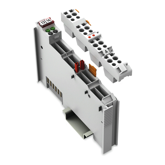
WAGO I/O-SYSTEM 750 753-501 Manual (54 pages)
2DO 24V DC 0,5A 2-Channel Digital Output Module 24 V DC, Short-circuit protected; high-side switching
Brand:
WAGO
| Category:
I/O Systems
| Size: 2.47 MB
Table of Contents
Table of Contents
3
Notes about this Documentation
5
Validity of this Documentation
5
Copyright
5
Table 1: Variants
5
Symbols
6
Number Notation
8
Font Conventions
8
Table 2: Number Notation
8
Table 3: Font Conventions
8
Important Notes
9
Legal Bases
9
Subject to Changes
9
Personnel Qualifications
9
Use of the WAGO-I/O-SYSTEM 750 in Compliance with Underlying Provisions
9
Technical Condition of Specified Devices
10
Safety Advice (Precautions)
11
Device Description
13
View
15
Figure 1: View
15
Table 4: Legend for Figure "View
15
Connectors
16
Data Contacts/Internal Bus
16
Figure 2: Data Contacts
16
Power Jumper Contacts/Field Supply
17
Figure 3: Power Jumper Contacts
17
Table 5: Legend for Figure "Power Jumper Contacts
17
Cage Clamp
18
Figure 4: CAGE CLAMP ® Connectors
18
Table 6: Legend for Figure "CAGE CLAMP ® Connectors
18
Display Elements
19
Schematic Diagram
19
Figure 5: Display Elements
19
Figure 6: Schematic Diagram
19
Table 7: Legend for Figure "Display Elements
19
Technical Data
20
Device Data
20
Power Supply
20
Communication
20
Outputs
20
Table 8: Technical Data - Device
20
Table 9: Technical Data - Power Supply
20
Table 10: Technical Data - Communication
20
Table 11: Technical Data - Outputs
20
Connection
21
Climatic Environmental Conditions
21
Table 12: Technical Data - Field Wiring
21
Table 13: Technical Data - Power Jumper Contacts
21
Table 14: Technical Data - Data Contacts
21
Table 15: Technical Data - Climatic Environmental Conditions
21
Approvals
22
Standards and Guidelines
23
Process Image
24
Table 16: Output Bits
24
Mounting
25
Mounting Sequence
25
Inserting and Removing Devices
26
Inserting the I/O Module
26
Figure 7: Insert I/O Module (Example)
26
Figure 8: Snap the I/O Module into Place (Example)
26
Removing the I/O Module
27
Figure 9: Removing the I/O Module (Example)
27
I/O Modules with Pluggable Wiring Level (Series 753)
28
Figure 10: Connector and Module
28
Figure 11: Assignment of Module to Connector Using Mini-WSB Tags
28
Figure 12: Attachment of Cable Binders
28
Coding
29
Figure 13: Assembling the Coding Fingers
29
Figure 14: Inserting the Coding Fingers
29
Figure 15: Plugging the Connector into Place
29
Figure 16: "Sure Match" Coding Fingers
30
Connector Removal
31
Figure 17: Pulling the Pull Tab
31
Figure 18: Removing the Connector Without Tools
31
Figure 19: Removing the Connector Using a Screwdriver
31
Connect Devices
32
Connecting a Conductor to the CAGE CLAMP
32
Figure 20: Connecting a Conductor to a CAGE CLAMP
32
Connection Examples
33
2-Conductor Connection, Ungrounded
33
2-Conductor Connection, Grounded
33
Figure 21: Connecting Diagram, 2-Conductor Connection, Ungrounded
33
Figure 22: Connecting Diagram, 2-Conductor Connection, Grounded
33
3-Conductor Connection, Ungrounded
34
3-Conductor Connection, Grounded
34
Figure 23: Connecting Diagram, 3-Conductor Connection, Ungrounded
34
Figure 24: Connecting Diagram, 3-Conductor Connection, Grounded
34
Using Interference-Free Variants of I/O Modules in Safety Related Applications
35
Important Notes
36
Connecting the IO Module to Safety Switching Devices or Safety Modules
37
General Structure
37
Figure 25: Potential Group for Safety Related Applications
37
Examples of Connection
38
Figure 26: Two-Channel Single-Pole Disconnection
38
Figure 27: Two-Channel Double-Pole Disconnection
38
Use in Hazardous Environments
39
Marking Configuration Examples
40
Marking for Europe According to ATEX and IEC-Ex
40
Figure 28: Side Marking Example for Approved I/O Modules According to ATEX and Iecex
40
Figure 29: Text Detail - Marking Example for Approved I/O Modules According to ATEX and Iecex
40
Table 17: Description of Marking Example for Approved I/O Modules According to ATEX and Iecex
41
Table 19: Description of Marking Example for Approved I/O Modules
41
Figure 30: Side Marking Example for Approved Ex I I/O Modules According to ATEX and Iecex
42
Figure 31: Text Detail - Marking Example for Approved Ex I I/O Modules According to ATEX and Iecex
42
Table 18: Description of Marking Example for Approved Ex I I/O Modules According to ATEX and Iecex
44
Marking for America According to NEC 500
45
Figure 32: Side Marking Example for I/O Modules According to NEC 500
45
Figure 33: Text Detail - Marking Example for Approved I/O Modules
45
Installation Regulations
46
Special Conditions for Safe Use (ATEX Certificate TÜV 07 ATEX 554086 X)
47
Special Conditions for Safe Use (ATEX Certificate TÜV 12 ATEX 106032 X)
48
Special Conditions for Safe Use (IEC-Ex Certificate TUN 09.0001 X)
49
Special Conditions for Safe Use (IEC-Ex Certificate Iecex TUN 12.0039 X)
50
Special Conditions for Safe Use According to ANSI/ISA
51
List of Figures
52
List of Tables
53
Advertisement
Advertisement
Related Products
WAGO I/O SYSTEM 750 750-671
WAGO I/O SYSTEM 750 750-833
WAGO I/O SYSTEM 750 750-635
WAGO I/O SYSTEM 750 750-641
WAGO I/O SYSTEM 750 750-421
WAGO I/O System 750 750-460
WAGO I/O System 750 750-622
WAGO I/O System 750 750-483
WAGO I/O System 750/753
WAGO 750-344
WAGO Categories
I/O Systems
Control Unit
Power Supply
Switch
Controller
More WAGO Manuals
Login
Sign In
OR
Sign in with Facebook
Sign in with Google
Upload manual
Upload from disk
Upload from URL