Sign In
Upload
Manuals
Brands
VOLKSWAGEN Manuals
Automobile
2005 Golf Plus
VOLKSWAGEN 2005 Golf Plus Manuals
Manuals and User Guides for VOLKSWAGEN 2005 Golf Plus. We have
4
VOLKSWAGEN 2005 Golf Plus manuals available for free PDF download: Workshop Manual, Service Manual, Service Training Manual, Brochure
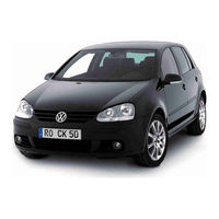
Volkswagen 2005 Golf Plus Workshop Manual (418 pages)
Brand:
Volkswagen
| Category:
Automobile
| Size: 10.91 MB
Table of Contents
Table of Contents
3
Technical Data
9
Checklist for Evaluating Running Gear of Accident Vehicles
9
General Information
11
Front Suspension
12
Appraisal of Accident Vehicles
12
Repairing Front Suspension
13
Overview - Front Axle
13
Raising Wheel Suspension to Unladen Position, Golf
14
Raising Wheel Suspension to Unladen Position, Golf Plus, Crossgolf
16
Subframe, Anti-Roll Bar, Suspension Link
18
Assembly Overview: Subframe, Anti-Roll Bar, Suspension Links
18
Assembly Overview - Front Left Vehicle Level Sender G78
22
Removing and Installing Front Left Vehicle Level Sender G78
23
Repairing Thread in Longitudinal Member
24
Fixing Position of Subframe and Brackets
24
Lowering Subframe
25
Removing and Installing Subframe Without Steering Box
29
Removing and Installing Subframe with Steering Box
31
Repairing Subframe (Front-Wheel Drive)
36
Repairing Subframe (Four-Wheel Drive)
39
Checking Swivel Joint
41
Removing and Installing Swivel Joint
42
Removing and Installing Suspension Link with Mounting Bracket
44
Removing and Installing Suspension Link with Mounting Bracket (Left Side for Vehicles with DSG or Automatic Gearboxes)
47
Removing and Installing Suspension Link with Mounting Bracket (Right Side for Vehicles with 6-Cylinder Engines)
51
Renewing Bonded Rubber Bush for Suspension Link
55
Renewing Mounting Bracket with Suspension Link Bush
57
Removing and Installing Anti-Roll Bar
59
Assembly Overview - Wheel Bearing
64
Removing and Installing Wheel Bearing Housing (3-Point Mounting)
65
Removing and Installing Wheel Bearing Housing (4-Point Mounting)
66
Removing and Installing Wheel Bearing Housing
68
Assembly Overview: Suspension Strut
72
Removing and Installing Suspension Strut, Golf
73
Removing and Installing Suspension Strut, Golf Plus, Crossgolf
78
Repairing Suspension Strut
83
Removing and Installing Drive Shafts
85
Loosening and Tightening Drive Shaft Hexagon Bolt
85
Loosening and Tightening 12-Point Flange Bolt Securing Drive Shaft
86
Removing and Installing Drive Shaft with Constant Velocity Joint
87
Removing and Installing Left Drive Shaft with (Push-On) Constant Velocity Slip Joint
89
Removing and Installing Right Drive Shaft with (Push-On) Constant Velocity Slip Joint
93
Removing and Installing Drive Shafts with Triple Roller Joint Aar2600I
96
Removing and Installing Drive Shafts with Triple Roller Joint Aar3300I
98
Removing and Installing Intermediate Shaft
100
Repairing Drive Shaft - Overview of Drive Shafts
102
Heat Shields for Drive Shafts
104
Assembly Overview - Drive Shaft with VL90 or VL100 Constant Velocity Joint
105
Dismantling and Assembling Drive Shaft with VL90 or VL100 Constant Velocity Joint
107
Checking Outer Constant Velocity Joint
111
Checking Inner Constant Velocity Joint
112
Assembly Overview - Drive Shaft with VL107 Constant Velocity Joint (Bolt-On)
115
Dismantling and Assembling Drive Shaft with VL107 Constant Velocity Joint
117
Repairing Intermediate Shaft
122
Assembly Overview - Drive Shaft with VL107 Constant Velocity Slip Joint (Push-On)
124
Dismantling and Assembling Drive Shaft with VL107 (Push-On) Constant Velocity Slip Joint
125
Checking Outer Constant Velocity Joint
127
Assembly Overview - Drive Shaft with Triple Roller Joint Aar2600I
129
Dismantling and Assembling Drive Shaft with Triple Roller Joint Aar2600I
130
Assembly Overview - Drive Shaft with Triple Roller Joint Aar3300I
135
Dismantling and Assembling Drive Shaft with Triple Roller Joint Aar3300I
137
Rear Suspension
142
Appraisal of Accident Vehicles
142
Repairing Rear Suspension (Front-Wheel Drive)
143
Overview - Rear Axle
143
Rear Axle in Unladen Position, Golf
144
Rear Axle in Unladen Position, Golf Plus, Crossgolf
146
Assembly Overview: Subframe, Transverse Link, Track Rod (Front-Wheel Drive)
148
Removing and Installing Rear Axle
151
Vehicle Level Sender for Vehicles with Automatic Headlight Range Control
156
Renew Vehicle Level Sender in Vehicle
156
Removing and Installing Upper Transverse Link
157
Removing and Installing Lower Transverse Link
159
Removing and Installing Track Rod
160
Assembly Overview: Wheel Bearing Housing, Trailing Arm (Front-Wheel Drive)
164
Removing and Installing Wheel Bearing Housing
165
Renewing Bonded Rubber Bush for Wheel Bearing Housing
169
Removing and Installing Wheel Bearing/Wheel Hub Unit
172
Removing and Installing Trailing Arm with Mounting Bracket
174
Repairing Trailing Arm
178
Assembly Overview: Shock Absorber, Coil Spring (Front-Wheel Drive)
181
Removing and Installing Coil Spring
181
Removing and Installing Shock Absorbers
183
Repairing Shock Absorber
185
Assembly Overview: Anti-Roll Bar (Front-Wheel Drive)
187
Removing and Installing Anti-Roll Bar
187
Assembly Overview - Attachment Parts for Subframe Golf Bluemotion, Golf Plus Bluemotion (Front-Wheel Drive)
190
Repairing Rear Suspension (Four-Wheel Drive)
191
Overview of Rear Axle (Aluminium)
191
Overview of Rear Axle (Steel)
193
Rear Axle in Unladen State (Aluminium and Steel)
195
Assembly Overview - Subframe Made from Aluminium, Final Drive (Four-Wheel Drive)
197
Removing and Installing Rear Axle
197
Repairing Subframe
203
Assembly Overview - Subframe Made from Steel, Final Drive (Four-Wheel Drive)
207
Removing and Installing Rear Axle
207
Repairing Subframe
213
Assembly Overview - Control Arm, Track Rod (Four-Wheel Drive, Subframe Made from Aluminium and Wheel Bearing Housing Made from Cast Steel)
220
Overview - Rear Left Vehicle Level Sender G76
222
Renew Vehicle Level Sender in Vehicle
223
Removing and Installing Upper Transverse Link
223
Removing and Installing Lower Transverse Link
225
Removing and Installing Track Rod
227
Assembly Overview - Control Arm, Track Rod (Four-Wheel Drive, Subframe Made from Steel and Wheel Bearing Housing Made from Aluminium)
231
Overview - Rear Left Vehicle Level Sender G76
234
Renew Vehicle Level Sender in Vehicle
234
Removing and Installing Upper Transverse Link
235
Removing and Installing Lower Transverse Link
237
Removing and Installing Track Rod
239
Assembly Overview - Wheel Bearing Housing, Trailing Link (Four-Wheel Drive, Subframe Made from Aluminium and Wheel Bearing Housing Made from Cast Steel)
242
Changing from Wheel Housing Bearing Made from Cast Steel to Wheel Bearing Housing Made from Aluminium
243
Removing and Installing Wheel Bearing Housing
244
Renewing Bonded Rubber Bush for Wheel Bearing Housing
248
Removing and Installing Wheel Bearing/Wheel Hub Unit
250
Removing and Installing Trailing Arm with Mounting Bracket
251
Repairing Trailing Arm
256
Assembly Overview - Wheel Bearing Housing, Trailing Link (Four-Wheel Drive, Subframe Made from Steel and Wheel Bearing Housing Made from Aluminium)
259
Removing and Installing Wheel Bearing Housing
260
Renewing Bonded Rubber Bush for Wheel Bearing Housing
263
Removing and Installing Wheel Bearing/Wheel Hub Unit
263
Assembly Overview - Shock Absorber, Coil Spring (Four-Wheel Drive, Subframe Made from Aluminium and Wheel Bearing Housing Made from Cast Steel)
265
Removing and Installing Coil Spring
265
Removing and Installing Shock Absorbers
267
Repairing Shock Absorber
268
Assembly Overview - Shock Absorber, Coil Spring (Four-Wheel Drive, Subframe Made from Steel and Wheel Bearing Housing Made from Aluminium)
270
Removing and Installing Coil Spring
270
Removing and Installing Shock Absorbers
270
Repairing Shock Absorber
272
Assembly Overview - Anti-Roll Bar (Four-Wheel Drive, Subframe Made from Aluminium and Wheel Bearing Housing Made from Cast Steel)
273
Removing and Installing Anti-Roll Bar
273
Assembly Overview - Anti-Roll Bar (Four-Wheel Drive, Subframe Made from Steel and Wheel Bearing Housing Made from Aluminium)
277
Removing and Installing Anti-Roll Bar
277
Assembly Overview - Drive Shaft
281
Loosening and Tightening Drive Shaft Hexagon Bolt
282
Loosening and Tightening 12-Point Bolt for Drive Shaft
283
Removing and Installing Drive Shaft
284
Dismantling and Assembling Drive Shaft
286
Checking Outer Constant Velocity Joint
291
Checking Inner Constant Velocity Joint
292
Wheels, Tyres, Vehicle Geometry
295
Appraisal of Accident Vehicles
295
Torque Settings for Wheel Bolts
296
Fitting Wheel and Tyre
297
General Information
297
Removing and Fitting Tyres (Wheels with Tyre Pressure Monitoring)
298
Notes on Safety and Conditions for Removing and Fitting Tyres
298
Monitoring)
298
Wheel Change
298
Pressing Tyre off Wheel Rim
299
Removing Tyre from Wheel
300
Fitting Tyre to Wheel Rim
300
Removing and Fitting Tyres with Run-Flat Capability to Wheel Rims
302
Notes on Safety
302
Installation Conditions
302
Pressing Tyre off Wheel Rim
304
Removing Tyre from Wheel
304
Fitting Tyre to Wheel Rim
306
Tyre Monitor Display
308
Tyre Pressure Monitor (TPM)
310
Button Behaviour
310
Assembly Overview - Tyre Pressure Sensor
311
Removing and Installing Tyre Pressure Sensor
312
Wheel Alignment
313
General
313
Test Prerequisites
315
Test Preparations
315
Wheel Alignment Specifications, Golf
316
Wheel Alignment Specifications, Golf Plus, Crossgolf
317
Overview - Wheel Alignment Procedure
319
Correcting Front Axle Camber
320
Adjusting Camber on Rear Axle
322
Adjusting Toe at Rear Axle
323
Adjusting Front Axle Toe
324
Basic Setting for Steering Angle Sender G85
325
Vehicle Data Sticker
325
Wheels, Tyres
326
Models with Breakdown Set
326
Tyre Sealant
326
Removing a Tyre
326
Fitting a New Tyre
327
Tyre Sealant Disposal
327
Alloy Wheels with Metal Valves
327
Instructions for Changing or Fitting Wheels
329
Fitting Wheels
330
Protecting Wheel Centring Seat against Corrosion
331
Rough Running Due to Wheels/Tyres - Causes and Rectification
332
Causes of Rough Running
332
Balancing Wheels
332
Conducting a Road Test before Balancing Wheels
333
Balancing Wheels on Stationary Wheel Balancing Machine
333
Vibration Control System VAS 6230
335
Finish Balancer
335
Radial and Lateral Runout of Wheels and Tyres
336
Checking Radial and Lateral Runout on Wheels and Tyres with Tyre Gauge V.A.G 1435
336
Checking Radial and Lateral Runout on Wheel
337
Matching
338
Flat Spots Caused by Storage or Handling
339
Steering
341
Appraisal of Accident Vehicles
341
General Repair Instructions
342
Steering Box
342
Gaskets and Seals
342
Nuts and Bolts
342
Electrical Components
343
Guided Fault-Finding, Vehicle Self-Diagnosis and Test Instruments
343
Steering Wheel
344
Removing and Installing Steering Wheel
344
Steering Column, Golf
347
Assembly Overview: Steering Column
347
Removing and Installing Steering Column
347
Basic Setting for Steering Angle Sensor G85 Steering Angle Sender Must be Checked after the Following Repair Work
353
Handling and Transporting Steering Column
353
Checking Steering Column for Damage
354
Removing and Installing Mounting Bracket
354
Removing and Installing Strut
356
Steering Column, Golf Plus, Crossgolf
359
Assembly Overview: Steering Column
359
Removing and Installing Steering Column
359
Basic Setting for Steering Angle Sensor G85 Steering Angle Sender Must be Checked after the Following Repair Work
365
Handling and Transporting Steering Column
365
Checking Steering Column for Damage
366
Removing and Installing Mounting Bracket
366
Removing and Installing Strut
368
Electromechanical Steering Box up to Model Year 2008
371
Assembly Overview - Electromechanical Steering Box, Left-Hand Drive (1St and 2Nd Generations) up to Model Year 2008
371
Assembly Overview - Electromechanical Steering Box, Right-Hand Drive (2Nd Generation) up
373
To Model Year 2008
373
Year 2008
374
Removing and Installing Steering Box, Right-Hand Drive (2Nd Generation) up to Model Year
382
Electromechanical Steering Box after Model Year 2009
391
Assembly Overview - Electromechanical Steering Box, Left-Hand Drive (3Rd Generation) after
391
Model Year 2009
391
Assembly Overview - Electromechanical Steering Box, Right-Hand Drive (3Rd Generation) after
392
Model Year 2009
392
Removing and Installing Steering Box, Left-Hand Drive (3Rd Generation) after Model Year
393
Removing and Installing Steering Box, Right-Hand Drive (3Rd Generation) after Model Year
399
Distinguishing between Steering Boxes (1St and 2Nd Generations), Golf
406
Differentiating between 2Nd and 3Rd Generation Steering Boxes
407
Exchanging 1St Generation Steering Box for 2Nd Generation Steering Box, Golf
408
Repairing Electromechanical Steering Box (1St Generation), Golf
409
Removing and Installing Boot
409
Removing and Installing Track Rod
411
Repairing Electromechanical Steering Box (2Nd and 3Rd Generations)
414
Removing and Installing Boot
414
Removing and Installing Track Rod
416
Advertisement
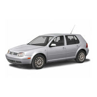
Volkswagen 2005 Golf Plus Service Manual (207 pages)
4-cylinder diesel engine (1.9 l engine)
Brand:
Volkswagen
| Category:
Automobile
| Size: 7.53 MB
Table of Contents
Table of Contents
3
Technical Data
7
Engine Number
7
Engine Data
7
Removing and Installing Engine
8
Removing Engine
8
Securing Engine to Assembly Stand
13
Notes on Installing
13
Assembly Mountings
16
Crankshaft Group
18
Dismantling and Assembling Engine
18
Assembly Overview - Poly V-Belt Drive
18
Removing and Installing Poly V-Belt
19
Assembly Overview - Toothed Belt Drive
21
Assembly Overview - Crankcase
25
Removing and Installing Sealing Flange and Flywheel
26
Assembly Overview - Sealing Flanges and Flywheel
26
Renewing Crankshaft Oil Seal - Pulley End
27
Removing and Installing Sealing Flange - Pulley End
29
Renewing Crankshaft Sealing Flange - Flywheel End
31
Removing and Installing Engine Speed Sender G28
37
Crankshaft
39
Assembly Overview - Crankshaft
39
Crankshaft Dimensions
44
Pistons and Conrods
45
Assembly Overview - Pistons and Conrods
45
Separating New Conrod
46
Checking Piston Projection at TDC
47
Piston and Cylinder Dimensions
48
Piston Rings, Cylinder Bore and Piston Installation Position
48
Cylinder Head, Valve Gear
50
Cylinder Head
50
Assembly Overview - Cylinder Head
51
Removing and Installing Cylinder Head Cover
54
Removing, Installing and Tensioning Toothed Belts
56
Removing and Installing Cylinder Head
73
Checking Compression
77
Valve Gear
80
Assembly Overview - Valve Gear
80
Checking Valve Guides
82
Renewing Valve Stem Seals
84
Removing and Installing Camshaft
86
Removing and Installing Camshaft Oil Seal
90
Lubrication
92
Engine Oil
92
Oil Capacities
92
Checking Engine Oil Level
92
Parts of Lubrication System
93
Assembly Overview - Oil Pump, Sump
93
Removing and Installing Sump
94
Oil Filter Bracket, Oil Pressure, Engine Oil Cooler and Oil Supply Line
98
Assembly Overview - Oil Filter Bracket and Engine Oil Cooler
98
Checking Oil Pressure and Oil Pressure Switch
99
Assembly Overview - Oil Supply Line to Turbocharger
100
Removing and Installing Oil Supply Line to Turbocharger
101
Cooling
103
Parts of Cooling System
103
Parts of Cooling System, Body Side
104
Parts of Cooling System, Engine Side
105
Coolant Hose Schematic Diagram
107
Draining and Filling with Coolant
108
Removing and Installing Radiator
111
Removing and Installing Coolant Pump
112
Removing and Installing Thermostat
114
Checking Cooling System for Leaks
116
Checking Engine Oil Cooler for Leaks
118
Fuel Supply System
120
Safety Precautions When Working on Fuel Supply System
120
Rules for Cleanliness
121
Fuel Tank, Vehicles with Front-Wheel Drive
122
Assembly Overview - Fuel Tank
122
Emptying Fuel Tank
123
Removing and Installing Fuel Tank
127
Removing and Installing Fuel Delivery Unit
129
Removing and Installing Fuel Gauge Sender
130
Checking Fuel Pump
131
Fuel Tank, Vehicles with Four-Wheel Drive
133
Assembly Overview - Fuel Tank
133
Emptying Fuel Tank
134
Removing and Installing Fuel Tank
138
Removing and Installing Fuel Gauge Sender 2 G169
141
Removing and Installing Suction-Jet Pump
143
Checking Fuel Pump
144
Repairing Fuel Supply System
146
Assembly Overview - Fuel Filter
146
Removing and Installing Fuel Cooler
147
Assembly Overview - Accelerator Mechanism
148
Checking Tandem Pump
149
Removing and Installing Tandem Pump
153
Turbocharging/Supercharging
157
Charge Air System with Turbocharger
157
Safety Precautions
157
Rules for Cleanliness
157
Assembly Overview - Turbocharger
158
Removing and Installing Turbocharger
162
Assembly Overview - Parts of Charge Air Cooling
164
Hose Connections
167
Checking Charge Air System for Leaks
168
Vacuum Hose Schematic Diagram
170
Mixture Preparation - Injection
172
Diesel Direct Injection System
172
Safety Precautions
172
Rules for Cleanliness
173
Assembly Overview - Unit Injector
173
Removing and Installing Unit Injector
175
Adjusting Non-Contact Gap of Unit Injectors
177
Removing and Installing O-Rings for Unit Injector
178
Assembly Overview - Intake Manifold
180
Cleaning the Intake Manifold Flap Support, Engine Code BLS and BXJ
182
Assembly Overview - Air Filter
183
Engine Control Unit
184
Reading and Erasing Engine Control Unit Fault Memory
184
Adapting Functions and Components
185
Removing and Installing Engine Control Unit, Golf
186
Removing and Installing Anti-Theft Engine Control Unit, Golf
186
Removing and Installing Engine Control Unit, Golf Plus
189
Removing and Installing Anti-Theft Engine Control Unit, Golf Plus
189
Exhaust System
192
Assembly Overview - Front Exhaust Pipe with Catalytic Converter
192
Assembly Overview - Front Exhaust Pipe with Particulate Filter
193
Assembly Overview - Silencer with Mountings (Vehicles with Front Wheel Drive)
195
Assembly Overview - Silencer with Mountings (Vehicles with Four-Wheel Drive)
197
Aligning Exhaust System Free of Stress
198
Exhaust Gas Recirculation System
199
Assembly Overview - Parts of Exhaust Gas Recirculation
199
Glow Plug System
204
Checking Glow Plug System
204
Removing, Installing and Checking Glow Plugs
204
Characteristics of Ceramic Glow Plugs
205
Removing, Installing and Checking Ceramic Glow Plugs
206
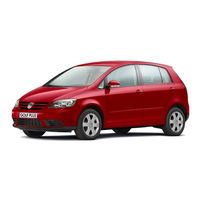
Volkswagen 2005 Golf Plus Service Training Manual (56 pages)
Self-study programme 338
Brand:
Volkswagen
| Category:
Automobile
| Size: 3.8 MB
Table of Contents
Table of Contents
3
In Brief
4
Technical Data
6
Body
8
Height Adjustment
13
Pedestrian Protection
16
Occupant Protection
18
Engine-Gearbox Combinations
20
Engines
22
Power Transmission
26
Running Gear
28
Electrical System
30
Trailer Detector Control Unit J345
34
Convenience Electronics
38
Radio and Navigation
44
Climate Control
48
Heater and Air Conditioner
48
Special Tools
55
Service
55
Advertisement
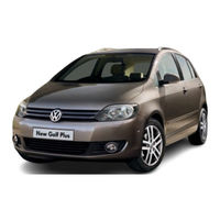
VOLKSWAGEN 2005 Golf Plus Brochure (21 pages)
Brand:
VOLKSWAGEN
| Category:
Automobile
| Size: 4.52 MB
Table of Contents
Contents
2
Engines and Gearboxes
12
Optional Equipment
14
Seat Upholstery
17
Technical Specification
18
Volkswagen Service
20
Advertisement
Related Products
Volkswagen 2004 Jetta
Volkswagen 2004 Golf
Volkswagen 2001 Passat
Volkswagen 2014 Golf
Volkswagen 2014 Beetle
Volkswagen 2015 Golf GTI
Volkswagen 2013 Passat
Volkswagen 2012 Golf
Volkswagen 2014 Touareg
Volkswagen 2013 Beetle
VOLKSWAGEN Categories
Automobile
Automobile Accessories
Adapter
Cables and connectors
Car Receiver
More VOLKSWAGEN Manuals
Login
Sign In
OR
Sign in with Facebook
Sign in with Google
Upload manual
Upload from disk
Upload from URL