Sign In
Upload
Manuals
Brands
Toshiba Manuals
Copier
1550
Toshiba 1550 Manuals
Manuals and User Guides for Toshiba 1550. We have
5
Toshiba 1550 manuals available for free PDF download: Service Manual, Service Handbook, Manual, Operator's Manual
Toshiba 1550 Service Manual (213 pages)
Brand:
Toshiba
| Category:
Copier
| Size: 4.71 MB
Table of Contents
2
General Preacutions
4
Specifications
7
Accessories
7
Options and Supplies
8
Outline of the Machine
8
Table of Contents
10
Front and Rear Sectional Views for the 1560
12
Electrical Parts Location Diagram
12
DC Electrical Parts Excluding Motors
12
Mirror
13
Electrical Parts such as Motors
14
AC Electrical Parts
14
Exposure Lamp
15
Symbol and Function of Electrical Parts
18
Wire-Harness Location Diagram
18
Location Diagram for Upper Unit
19
Location Diagram for Lower Unit
20
Removing Covers
20
Front Cover
20
Inner Cover
21
Right-Side Covers and Feed-Side Cover
22
Top Cover and Glass Holder
22
Rear Cover
23
Left-Top Cover, Left-Side Cover and Left-Side Cover
23
Raise the Upper Unit
24
Control Panel Cover
25
Removal and Installation of Electrical Parts
25
Remove the Control-Panel PC Board
26
Total Counter
26
Logic PC Board
26
Power Supply Unit
27
Door Switch and Main Switch
29
Main Switch Connector Connecting Diagram
29
Door Switch Connector Connecting Diagram
30
High-Voltage Transformer for the Main Charger
30
Size Switch
30
Exit Fan
31
Front Optics Fan
31
Fuse
31
Fuse PC Board
32
Main Motor
32
Lamp Regulator PC Board
33
Optics Fan
34
Copying Process
35
ED-1550/1560 Copying Process
37
Copier Operation
37
Operation Outline
37
Description of Operation
37
During Warm up
38
Aligning Operation
38
Carriage 2
41
Bypass-Feed Copying
41
Interrupt Copying
41
1550/1560
42
Fault Detection
46
Flow Charts
46
After Power Supply Is Turned on
48
Automatic Feed Copying
50
Display Unit
50
Control Panel and Indication Panel
51
Items Displayed on Control Panel
52
Relationship between Machine Condition and Operator’s Action
53
LED Display Circuit
53
LED Display Method
54
Conditions for LED to Come on
55
Drive Mechanism
55
Construction
55
Aligning Roller (Lower
56
Upper Unit Drive
56
Lower Unit Drive
57
Explanation of Functions
58
Disassembly and Replacement
58
Drum Drive Gear and Developer Drive Gear
58
Mirror
63
Lower Drive Unit
64
Main Motor Drive
65
Control Signal
65
Signal Level of Motor Circuit
66
Bypass Feed Section
66
Bypass Feed Roller
66
Removal of the Separation Pad
66
Removal of the Clutch
68
Optical System
68
Mirror Unit
69
Mirror
70
Explanation of Operation
70
Scanning Motor
71
Mirror Motor and Lens Motor
72
Immediately after the Power on
72
When a Reproduction Ratio Is Selected
72
Mirror
73
Auto Exposure PC Board and Damp Heater
73
Damp Heater
73
Auto Exposure PC Board
74
Mirror Motor
75
Lens Motor
75
Home Switch, Mirror Switch and Lens Switch
76
Exposure Lamp and Thermofuse
76
Original Glass
77
Carriage 1
78
Carriage Drive Wire
81
Mirror 6
82
Pulse Motor Drive Circuit
83
Form of Electric Wave that Flows into the Motor
84
Waveform Timing Chart of each Section
84
Equivalent Circuit of STK6712B
85
Pulse Motor Dirve Circuit
86
Exposure Control Circuit
86
Brief Description
87
Function of Lamp Regulator
87
Characteristics of the Curve of the Lamp Regulator
88
Automatic Exposure Sensor Circuit
88
Arithmetic and Control Unit
89
Lamp Regulator Circuit
90
Feeder Unit
90
Upper Paper Feeder Unit
90
Lower Paper Feeder Unit Turned Upside down
90
Aligning Roller (Upper
91
Paper Feeding Operation
91
Aligning Roller (Upper
92
Paper Separation Operation
92
Manual Feeding Operation
92
Cassette Feeding Operation
94
Upper Paper Feed Unit
94
Aligning Switch
95
Clutch and Aligning Rollers
96
Aligning Roller (Upper
97
Lower Paper Feed Unit
98
Empty Switch
100
Pick-Up Roller and Feed Roller
100
Pick-Up Roller Clutch and Feed Roller Clutch
101
Drum-Related Section
101
Discharge Lamp
102
Main Charger, Discharge Lamp and LED Erasing Array
102
Transfer/Separation Chargers
103
Process Unit
103
Discharge Lamp
103
Main Charger Unit
104
LED Erasing Array
104
Main Charger
105
Replacing the Cleaning Pad
106
Replacing the Charge Wire
107
Damp Heater Unit
108
Transfer/Separation Terminal
109
Main Charger Terminal
110
Transfer/Separation Electric Current Control Circuit
110
Description
110
Transfer/Separation Control Circuit Diagram
111
LED Eraser Array
113
High-Voltage Transformer (PS-HVT)
114
Developer Unit
114
Front Sectional View
115
Drive System
115
Magnetic Roller, Mixer 1 and Mixer 2
115
Toner Cartridge
116
Removal and Installation of the Developer Unit
116
Installing the Developer Material
118
Removing the Developer Material
119
Guide Rollers
119
Front Side
120
Rear Side
121
Toner Cartridge Drive Motor
121
Auto-Toner Sensor
122
Magnetic Roller
123
Brush Motor Drive
124
Auto-Toner Sensor Circuit
125
Operation of Auto-Toner Sensor
125
Functions of Auto-Toner Sensor
127
Cleaner Unit
127
View with the Drum, Main Charger Unit and Developer Unit Removed
127
View with the Drum Removed
127
Recovery Blade
128
Toner Recovery Auger
129
Drum
131
Main Blade
132
Toner Full Switch
133
Fuser and Paper Exit Section
133
View with the Fuser Guard Removed
133
View with the Upper Heat Roller Removed
134
Fuser Unit
134
Paper Exit Section
135
Heater Lamp
136
Thermostat, Thermistor and Brush
137
Cleaning Felt Roller and Cleaning Blade
137
Upper Heat Roller
137
Lower Heat Roller
138
Lower Exit Roller and Paper Exit Switch
139
Lever Caps
139
Separation Claws
139
Lower Exit Roller
139
Paper Exit Switch
141
Heater Control Circuit
141
Temperature Detection Unit
142
Thermistor Disconnection Detection
143
Optional Paper Feeding Unit
144
General Description
144
Names of the Main Components
144
View with the Rear Cover and Cassette Removed
145
Symbols and Functions of Electrical Parts
146
Functions and Operation
146
Aligning Roller (Upper
147
Detection and Clearing of Paper Jams
149
Covers and Paper Guide
149
Jam Access Cover
149
Paper Guide
151
Transport Rollers, Paper Stop Switch
151
Transport Roller Clutch and Door Switch
152
Transport Guide
153
Separation, Pick-Up and Feed Rollers
154
Lower Paper Feeding Unit
155
Drive Motor and Drive PC Board
157
Flow Chart
161
Timing Chart
161
A4 Lateral Single-Sheet Copying
161
A4 Lateral Two-Sheets Copying
162
Explanation of Circuits
162
Interface Signals
162
Signals from the Copier to the Paper Feeding Unit
162
Signals from the Paper Feeding Unit to the Copier
163
Driving of the Drive Motor
163
Current Route While the Motor Is Turned On/Off
164
Electric Circuit Diagram and PC Board Assembly
164
PFU Drive Circuit Diagram
165
Harness Location Diagram
166
Harness Connection Diagram
167
PC Board Assembly
168
Electrical Circuit Diagram
168
Logic Circuit
176
1560 Logic Circuit
184
Power Supply Circuit
185
Control Panel Circuit
189
Fuser Circuit
190
Power Stabilizing Circuit
191
Explanation of Circuit Operation
192
Pwa-F-Lgc
192
Pwa-F-Fus
193
Pwa-F-Pnl
193
Pwa-F-Aes
193
Pwa-F-Lrg
194
AC Harness Connection Diagram
194
AC Control Circuit
195
DC Harness Connection Diagram
197
Unpacking and Set-Up Procedure for the 1550
198
Installing the Copy Receiving Tray
199
Setting the Developer Unit
201
Adjustment Procedure
201
Automatic Adjustment of the Auto-Toner Sensor
202
Final Operation Check
202
Changing the Image Settings
202
Light Distribution Adjustment
202
Exposure Adjustment
203
Adjustment of Manual Exposure
204
Automatic Adjustment of Auto Exposure
205
Manual Adjustment of Exposure
206
Changing the Paper Size of the Cassette
207
Procedure for Installing the Toner Cartridge
208
Unpacking and Set-Up Procedure for the Paper Feeding Unit MY-1004
209
Installation Procedure
Advertisement
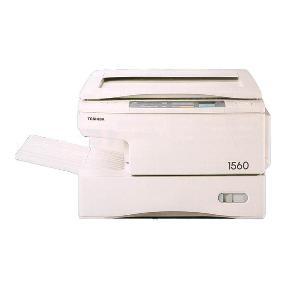
Toshiba 1550 Service Handbook (63 pages)
PLAIN PAPER COPIER PAPER FEEDING UNIT
Brand:
Toshiba
| Category:
Copier
| Size: 0.73 MB
Toshiba 1550 Manual (32 pages)
Analog Copiers - Detachable Options
Brand:
Toshiba
| Category:
Copier
| Size: 1.74 MB
Advertisement
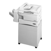
Toshiba 1550 Operator's Manual (31 pages)
plain paper copier
Brand:
Toshiba
| Category:
Copier
| Size: 1.54 MB
Toshiba 1550 Manual (6 pages)
ANALOG COPIERS, THE DISPUTABLE
Brand:
Toshiba
| Category:
Copier
| Size: 0.71 MB
Share and save
Advertisement
Related Products
Toshiba 120/150
Toshiba 1370
Toshiba 1360
Toshiba e-studio 150
Toshiba e-studio 120
Toshiba e-STUDIO 161
Toshiba 1560
Toshiba 1340
Toshiba 1350
Toshiba 15VL26P
Toshiba Categories
Laptop
Air Conditioner
TV
LCD TV
All in One Printer
More Toshiba Manuals
Login
Sign In
OR
Sign in with Facebook
Sign in with Google
Upload manual
Upload from disk
Upload from URL