Sign In
Upload
Manuals
Brands
Tektronix Manuals
Pulse Generator
SPG600
Tektronix SPG600 Manuals
Manuals and User Guides for Tektronix SPG600. We have
5
Tektronix SPG600 manuals available for free PDF download: Service Manual, User Manual, Quick Reference Manual, Instructions Manual
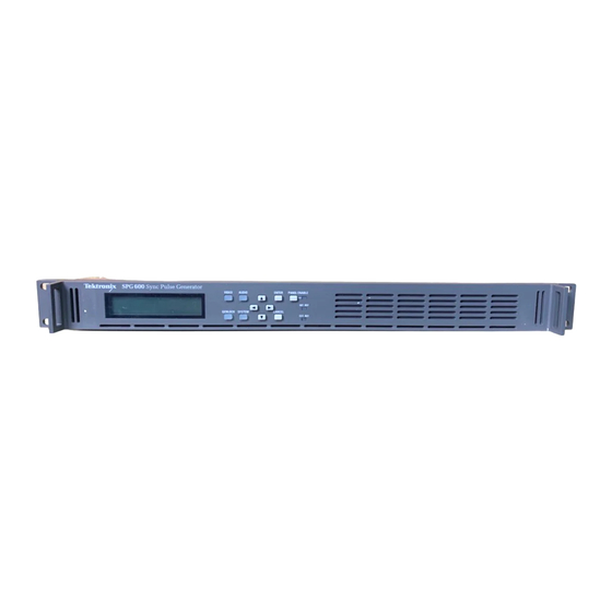
Tektronix SPG600 Service Manual (176 pages)
Sync Pulse Generators
Brand:
Tektronix
| Category:
Pulse Generator
| Size: 5.52 MB
Table of Contents
Table of Contents
5
General Safety Summary
13
Service Safety Summary
15
Preface
17
About this Manual
17
Manual Conventions
18
Finding Other Information
18
Introduction
19
Performance Check Interval
19
Strategy for Servicing
19
Tektronix Service Offerings
20
Product Overview
23
Table 1-1: Output Capability of the SPG600 and the SPG300
23
Specifications
25
General Characteristics
25
Table 1-1: Reference Inputs
26
Table 1-2: Analog Outputs (Standard and Option 02)
26
Table 1-3: Serial Digital Interface (Standard and Option 03)
27
Table 1-4: AES/EBU Audio Outputs
28
Table 1-5: Analog Audio Outputs
29
Table 1-6: GPI (General Purpose Interface)
29
Table 1-7: SNMP Error Report
29
Table 1-8: AC Power Source
30
Table 1-9: Clearance
30
Table 1-10: Mechanical Characteristics
30
Figure 1-1: SPG600 Dimensions
31
Figure 1-2: SPG300 Dimensions
32
Table 1-11: Environmental Characteristics
33
Installation
37
Supplying Operating Power
37
Table 2-1: Power-Cord Conductor Identification
38
Table 2-2: Power Cord Identification
39
Operating Environment
40
Applying and Interrupting Power
40
Repackaging Instructions
41
Installed Options
41
Menus
43
Video Menu
43
Figure 2-1: Video Menu Diagram
44
Figure 2-2: Test Signal (Analog) Submenu Diagram
45
Figure 2-3: Test Signal (SDI) Submenu Diagram
46
Figure 2-4: Timing (Analog) Submenu Diagram
47
Figure 2-5: Timing (SDI) Submenu Diagram
47
Figure 2-6: Overlay Submenu Diagram
48
Figure 2-7: Logo Submenu Diagram
49
Figure 2-8: ID Text Submenu Diagram
50
Figure 2-9: SDI Parameters Submenu
51
Figure 2-10: Audio Menu Diagram
52
Figure 2-11: AES/EBU Submenu Diagram
53
Figure 2-12: Embedded Submenu Diagram
54
Figure 2-13: Audio Channel Submenu Diagram
55
Genlock Menu
56
Figure 2-14: Genlock Menu Diagram
56
Figure 2-15: Genlock Timing Submenu Diagram
57
System Menu
58
Figure 2-16: System Menu Diagram
58
Figure 2-17: Preset Submenu Diagram
59
Figure 2-18: Network Information Submenu Diagram
60
Figure 2-19: Network Setup Submenu Diagram
61
Figure 2-20: GPI Submenu Diagram
62
Figure 2-21: System Information Submenu Diagram
63
Figure 2-22: System Setup Submenu Diagram
63
Figure 2-23: Configuration Submenu Diagram
64
Theory of Operation
65
A10 Main Board (SPG600) and A50 Main Board (SPG300)
67
A20 Front-Panel Board
69
Power Supply Module
70
Performance Verification
71
Preparation for Performance Verification
73
Equipment Required
73
Table 4-1: Equipment Required for Performance Verification
73
Calibration Data Report
74
Table 4-2: SPG600 and SPG300 Calibration Data Report
74
Performance Verification Procedures
76
Figure 4-1: Equipment Connection for Verifying Subcarrier Frequency
76
Figure 4-2: Equipment Connections for Verifying the Genlock Function
78
Figure 4-3: Equipment Connection for Verifying the Blanking Level
81
Figure 4-4: Equipment Connection for Verifying the Serial Digital
84
Outputs
84
Figure 4-5: Initial Equipment Connection for Verifying the Serial
88
Digital Audio Outputs
89
Audio Outputs
91
Audio Outputs
92
Output
94
Adjustment Procedure
97
Requirement for Adjustment
97
Equipment Required
97
Table 5-1: Equipment Required
97
Master Clock Frequency Adjustment
98
Figure 5-1: Equipment Connection for Adjusting Master Clock
98
Maintenance
101
Related Maintenance Procedures
103
Preparation
104
Inspection and Cleaning
104
Table 6-1: External Inspection Check List
105
Table 6-2: Internal Inspection Check List
106
Removal and Installation Procedures
107
Preparation
107
Table 6-1: Summary of Procedures
108
Figure 6-1: Instrument Orientation (SPG600)
109
Table 6-2: Tools Required for Module Removal
109
Figure 6-2: SPG600 External Modules
110
Figure 6-3: SPG600 Internal Modules
111
Figure 6-4: SPG300 External Modules
112
Figure 6-5: SPG300 Internal Modules
113
Removal and Installation Procedures Access Procedure
114
Access Procedure
114
Figure 6-6: Guide to Removal Procedures
114
Procedures for SPG600 External Modules
115
Top Cover
115
Figure 6-7: Top Cover Removal (SPG600)
116
Front-Panel Assembly
117
Figure 6-8: Front-Panel Assembly Removal (SPG600)
118
RFI Filter
118
Procedure for SPG600 Internal Modules
119
A30 Analog Board (Option 02)
119
A40 SDI Board (Option 03)
120
Figure 6-9: A30 Analog Board Removal
120
Figure 6-10: A40 SDI Board Removal
121
A10 Main Board
122
Figure 6-11: A10 Main Board Removal
123
Power Supply Module
123
Figure 6-12: Power Supply Module Removal (SPG600)
124
Procedures for SPG300 External Modules
125
Top Cover
125
Figure 6-13: Top Cover Removal (SPG300)
126
Front-Panel Assembly
126
Figure 6-14: Front-Panel Assembly Removal (SPG300)
127
RFI Filter
128
GPI Connector
128
Procedures for SPG300 Internal Modules
129
A60 Analog Board
129
Figure 6-15: A60 Analog Board Removal
130
A50 Main Board
130
Figure 6-16: A50 Main Board Removal
131
Power Supply Module
132
Figure 6-17: Power Supply Module Removal (SPG300)
133
Setting Main Board Parameters after Replacement
135
Setting the Instrument Serial Number
135
Installing the Option Key (Option 01 Only)
136
Setting the Date and Time
136
Troubleshooting
139
Figure 6-1: Troubleshooting Procedure (1)
140
Figure 6-2: Troubleshooting Procedure (2)
141
Figure 6-3: Troubleshooting Procedure (3)
142
Figure 6-4: Troubleshooting Procedure (4)
143
Figure 6-5: A10 Main Board View of SPG600
144
Figure 6-6: A10 Main Board View of SPG300
145
Options
147
Additional Features
149
Service Options
149
Electrical Parts List
151
Diagrams
155
Figure 9-1: SPG600 Block Diagram
158
Figure 9-2: SPG300 Block Diagram
159
Figure 9-3: Main Function Block Diagram
160
Figure 9-4: SPG600 Interconnect Diagram
161
Figure 9-5: SPG300 Interconnect Diagram
162
Mechanical Parts List
165
Using the Replaceable Parts List
166
Figure 10-1: SPG600 External Modules
169
Figure 10-2: SPG600 Internal Modules
171
Figure 10-3: SPG300 External Modules
173
Table: Replaceable Parts List (SPG300)
174
Figure 10-4: SPG300 Internal Modules
175
Advertisement
Tektronix SPG600 User Manual (132 pages)
Sync pulse generator
Brand:
Tektronix
| Category:
Pulse Generator
| Size: 1.66 MB
Table of Contents
Table of Contents
5
Preface
13
About this Manual
13
Contacting Tektronix
14
Getting Started
15
Product Description
17
Table 1-1: Output Capability between the SPG600 and the SPG300
18
Initial Product Inspection
18
Table 1-2: AC Line Power Requirement
19
Installation
19
Repackaging for Shipment
20
Functional Check Procedure
21
Standard Accessories
26
Table 1-3: Power Cord Identification
27
Optional Accessories
28
Options
28
Operating Basics
31
Figure 2-1: SPG600 Front Panel
33
Figure 2-2: SPG300 Front Panel
33
Front-Panel Buttons and Indicators
33
Figure 2-3: SPG600 Rear Panel (Option 0203)
35
Figure 2-4: SPG300 Rear Panel
35
Rear-Panel Connectors
35
Table 3-1: Instrument Menus and Information Pages
41
Figure 3-1: Example Menu Display
41
Menus
41
Video Menu
42
Figure 3-2: Video Menu Diagram
43
Figure 3-3: Test Signal (Analog) Submenu Diagram
46
Table 3-2: Selectable Signals in each Signal Set (Analog)
47
Figure 3-4: Test Signal (SDI) Submenu Diagram
49
Table 3-3: Selectable Signals in each Signal Set (SDI)
50
Figure 3-5: Timing (Analog) Submenu Diagram
51
Table 3-4: Analog Output Timing Range
52
Figure 3-6: Timing (SDI) Submenu Diagram
52
Table 3-5: SDI Output Timing Range
53
Figure 3-7: Overlay Submenu Diagram
53
Figure 3-8: Logo Submenu Diagram
54
Figure 3-9: ID Text Submenu Diagram
55
Figure 3-10: SDI Parameters Submenu Diagram
56
Figure 3-11: Audio Menu Diagram
57
Audio Menu
57
Figure 3-12: AES/EBU Submenu Diagram
59
Figure 3-13: Embedded Submenu Diagram
60
Figure 3-14: Audio Channel Submenu Diagram
61
Genlock Menu
63
Figure 3-15: Genlock Menu Diagram
63
Table 3-6: Genlock Timing Range
65
Figure 3-16: Genlock Timing Submenu Diagram
65
System Menu
66
Figure 3-17: System Menu Diagram
66
Figure 3-18: Preset Submenu Diagram
68
Figure 3-19: Network Information Submenu Diagram
70
Figure 3-20: Network Setup Submenu Diagram
71
Figure 3-21: GPI Submenu Diagram
74
Figure 3-22: System Information Submenu Diagram
75
Figure 3-23: System Setup Submenu Diagram
76
Figure 3-24: Configuration Submenu Diagram
77
Using the General Purpose Interface (GPI)
81
GPI Connector Pin Assignments
81
Figure 3-25: Pin Assignments of the GPI Connector
81
Table 3-7: Combinations of Signal Levels and the Corresponding Preset
82
Recalling a Preset
82
Figure 3-26: Input/Output Circuit of GPI
82
Outputting an Alarm Signal
83
Table 3-8: Factory Default Settings
85
Factory Default Settings
85
Appendix A: Specifications
91
General Characteristics
91
Table A-1: Reference Inputs
92
Table A-2: Analog Outputs (Standard and Option 02
92
Table A-3: Serial Digital Interface (Standard and Option 03
93
Table A-4: AES/EBU Audio Outputs
94
Table A-5: Analog Audio Outputs
95
Table A-6: GPI (General Purpose Interface
95
Table A-7: SNMP Error Report
95
Table A-8: AC Power Source
96
Table A-9: Clearance
96
Table A-10: Mechanical Characteristics
96
Figure A-1: SPG600 Dimensions
97
Figure A-2: SPG300 Dimensions
98
Table A-11: Environment Characteristics
99
Table A-12: Certifications and Compliances
100
Certifications and Compliances
100
Appendix B: Using the Remote Interface
103
Using a Web Browser
103
Figure B-1: Accessing the Remote Interface Using a Web Browser
104
Table B-1: Web Browser Interface Functions
104
Using the Java Applet for the Remote Interface
105
Figure B-2: Java Applet
106
Figure B-3: Java Applet Window
107
Table B-2: Remote Interface Menu
108
Figure B-4: Java Applet Window after Selecting the Genlock Tab
109
Figure B-5: File Transfer Setting Panel
110
Figure B-6: Select Logo Folder Dialog Box
111
Appendix C: Using Logo Generator
113
PC System Requirement
113
Installation Instructions
113
Starting and Exiting Logo Generator
115
Elements of the Logo Generator Window
116
Figure C-1: Logo Generator Application Window
116
Table C-1: Elements of the Logo Generator Window
117
Table C-2: Toolbar Button Description
117
Using the Logo Generator Menus
118
Table C-3: File Menu Commands
118
Table C-4: Build Menu Command
118
Table C-5: Setting Menu Commands
118
Figure C-2: Gray Scale Settings Dialog Box
119
Figure C-3: Miscellaneous Settings Dialog Box
120
Logo Generator Tutorials
121
Figure C-4: BMP to LGO File Conversion Dialog Box
121
Appendix D: Rackmounting the Instrument
123
Minimum Tool and Equipment List
123
Installation Instructions
124
Figure D-1: Assembly of Slide-Out Track Assemblies
125
In Rack (Top View)
126
Appendix E: User Maintenance
129
Cleaning
129
Preventive Maintenance
129
Tektronix SPG600 Quick Reference Manual (40 pages)
Sync Pulse Generator
Brand:
Tektronix
| Category:
Inverter
| Size: 0.32 MB
Table of Contents
Table of Contents
5
Related Manuals
7
Figure 1: SPG600 Front Panel
9
Figure 2: SPG300 Front Panel
9
Front-Panel Buttons and Indicators
9
Figure 3: SPG600 Rear Panel (Option 0203)
11
Rear-Panel Connectors
11
Figure 4: SPG300 Rear Panel
11
Menus
13
Figure 5: Video Menu Diagram
14
Figure 6: Test Signal (Analog) Submenu Diagram
15
Figure 7: Test Signal (SDI) Submenu Diagram
16
Figure 8: Timing (Analog) Submenu Diagram
17
Figure 9: Timing (SDI) Submenu Diagram
17
Figure 10: Overlay Submenu Diagram
18
Figure 11: Logo Submenu Diagram
19
Figure 12: ID Text Submenu Diagram
20
Figure 13: SDI Parameters Submenu
21
Figure 14: Audio Menu Diagram
22
Figure 15: AES/EBU Submenu Diagram
23
Figure 16: Embedded Submenu Diagram
24
Figure 17: Audio Channel Submenu Diagram
25
Figure 18: Genlock Menu Diagram
26
Figure 19: Genlock Timing Submenu Diagram
27
Figure 20: System Menu Diagram
28
Figure 21: Preset Submenu Diagram
29
Figure 22: Network Information Submenu Diagram
30
Figure 23: Network Setup Submenu Diagram
31
Figure 24: GPI Submenu Diagram
32
Figure 25: System Information Submenu Diagram
33
Figure 26: System Setup Submenu Diagram
33
Figure 27: Configuration Submenu Diagram
34
Rackmounting the Instrument (SPG600 Only)
35
Installation Instructions
36
Figure 28: Assembly of Slide-Out Track Assemblies (Right Slide-Out Track)
37
Figure 29: Installation of Slide-Out Track Assemblies in Rack (Top View)
38
Advertisement
Tektronix SPG600 Instructions Manual (14 pages)
Sync Pulse Generator Rackmount Kit
Brand:
Tektronix
| Category:
Racks & Stands
| Size: 0.38 MB
Table of Contents
Service Safety Summary
3
Kit Description
5
Installation Instructions
9
Rackmounting the Instrument
11
Tektronix SPG600 Instructions Manual (12 pages)
Sync Pulse
Brand:
Tektronix
| Category:
Portable Generator
| Size: 0.68 MB
Table of Contents
Service Safety Summary
3
Kit Description
5
Minimum Tool and Equipment List
5
Kit Parts List
6
Installation Instructions
7
Advertisement
Related Products
Tektronix SPG300
Tektronix SPG6UP 01
Tektronix SPG6UP 02
Tektronix SPG6UP 03
Tektronix SPG800AUP
Tektronix Tektronix SPG8000
Tektronix SPG3UP 01
Tektronix SPG 422
Tektronix SPG8000ABG
Tektronix SPG 1000
Tektronix Categories
Test Equipment
Measuring Instruments
Printer
Amplifier
Portable Generator
More Tektronix Manuals
Login
Sign In
OR
Sign in with Facebook
Sign in with Google
Upload manual
Upload from disk
Upload from URL