Sign In
Upload
Manuals
Brands
Tektronix Manuals
Inverter
SPG8000A
Tektronix SPG8000A Manuals
Manuals and User Guides for Tektronix SPG8000A. We have
7
Tektronix SPG8000A manuals available for free PDF download: User Manual, Service Manual, Installation And Safety Instructions, Instructions Manual, Operation Instructions Manual
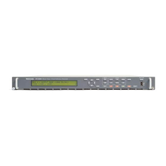
Tektronix SPG8000A User Manual (288 pages)
Master Sync / Clock Reference Generator Technical Reference
Brand:
Tektronix
| Category:
Measuring Instruments
| Size: 8 MB
Table of Contents
Table of Contents
5
Important Safety Information
14
General Safety Summary
14
Service Safety Summary
16
Terms in this Manual
17
Symbols and Terms on the Product
17
Preface
19
Product Description
19
Figure I: SPG8000A Front and Rear Panels
20
Methods of Operation
22
Product Documentation
23
Table I: Product Documentation
23
System Timing
25
Frame Reset Signals
25
GPS and GLONASS Signal Quality (Option GPS Only)
26
Table 1: Figures of Merit for GPS And/Or GLONASS Signal Quality (Option GPS Only)
28
Time Flow Block Diagram
29
Figure 1: Time Flow Block Diagram
30
Web User Interface
35
Operational Considerations
35
Elements of the Web User Interface
36
Figure 2: Example SPG8000A Web User Interface Window
36
Table 2: Elements of the Web User Interface
37
SNMP Remote Control
39
SNMP Configuration
39
Table 3: SNMP Parameters
39
Download the MIB
40
How to Backup/Restore Presets and User Data
41
How the Backup and Restore Operations Work
41
Memory Requirements
42
Backup/Restore Procedure
43
How to Transfer or Install User Files
45
To Transfer or Install User Files Using FTP
45
Figure 3: Example FTP View of the SPG8000A File Structure
46
Figure 4: Example FTP Error Message When Flash Memory Is Full
46
To Transfer or Install User Files Using a USB Drive
47
Figure 5: File Structure for Installing Custom User Files
50
How to Upgrade the Instrument Firmware
51
Determine if a Firmware Upgrade Is Needed
51
Firmware Upgrade Overview
53
USB Firmware Upgrade
53
Network Firmware Upgrade
56
Figure 6: Sample of Transfer.exe Window after the Upgrade Is Complete
57
Verify the Firmware Upgrade and Reinstall User Files
58
Firmware Upgrade Troubleshooting
58
How to Operate an Instrument with Two Power Supplies (Option DPW Only)
60
Power Supply Status
60
To Configure the Preferred (Active) Supply
61
To Hot-Swap a Power Supply Module
63
Figure 7: Removing a Power Supply Module
64
How to Use Stay Genlock
65
About Stay Genlock
65
To Enable Stay Genlock
65
AES Menu
67
Figure 8: AES Menu
67
Global Settings
68
Channel Parameters
69
AES Menu Factory Default Settings
70
Table 4: AES Global Settings Factory Default Settings
70
Table 5: AES Channel Parameters Factory Default Settings
70
Black Menu
71
Figure 9: Black Menu with the Black 2 Submenu Expanded
71
Figure 10: Composite Menu
77
Composite Output Settings
78
Table 9: Composite Output Test Signals
78
Composite Timecode Settings
79
Composite Timing Settings
79
Table 10: Timing Adjustment Ranges for Composite Output Signals
79
Composite Menu Factory Default Settings
81
Table 11: Composite Menu Factory Default Settings
81
Black Output Settings
72
Table 6: Black Output Formats
72
Black Timing Settings
73
Table 7: Black Output Timing Adjustment Ranges
73
Black Timecode Settings
74
Blank on Reference Unlock Settings
75
HD Tri-Level Sync Rate
75
Black Menu Factory Default Settings
76
Table 8: Black Menu Factory Default Settings
76
Composite Menu (Option BG Only)
77
Figure 11: Dolby-E Configuration Menu
83
Dolby-E Channel Configuration
84
Dolby-E METADATA
84
Dolby-E Generated Formats
87
Table 12: Dolby E Generated Formats - 23.98 Hz Frame Rate
87
Table 13: Dolby E Generated Formats - 24 Hz Frame Rate
88
Table 14: Dolby E Generated Formats - 25 Hz Frame Rate
90
Table 15: Dolby E Generated Formats - 29.97 Hz Frame Rate
91
Table 16: Dolby E Generated Formats - 30 Hz Frame Rate
92
Table 17: Dolby E Loudness Measurements - 23.98 and 24 Hz Frame Rates
93
Table 18: Dolby E Loudness Measurements - 25 Hz Frame Rate
94
Table 19: Dolby E Loudness Measurements - 29.97 and 30 Hz Frame Rates
94
Dolby-E Configuration Menu Factory Default Settings
95
Table 20: Dolby-E Configuration Menu Factory Default Settings
95
Dolby-E Configuration Menu (Option DBT Only)
83
Embedded Menu (Option SDI Only)
97
Figure 12: Partial Embedded Menu Diagram
98
Figure 13: LTC Menu with LTC 1 Selected
101
LTC Menu Factory Default Settings
102
Table 22: LTC Output Signal Formats
102
Table 23: LTC Button Menu Factory Default Settings
102
Embedded Menu Factory Default Settings
100
Table 21: Embedded Menu Factory Default Settings
100
LTC Menu
101
Reference Menu
103
Figure 14: Reference Tab Menu
103
Reference Settings
103
Ptp
104
Gps
105
Genlock Timing Settings
108
Table 24: Timing Adjustment Ranges for Reference Input Signals
108
Reference Menu Factory Default Settings
109
Table 25: Reference Menu Factory Default Settings
109
Figure 15: SDI Menu with the SDI 1 Submenu Expanded
111
Figure 16: SDI Signal Submenu
112
SDI Signal Submenu
112
Figure 17: Circle Zone Plate Configuration Parameters
116
SDI Configure Zoneplate Submenu
116
Figure 18: Configure Zoneplate Video Menu Selections
117
Figure 19: Configure Zoneplate Parameters for All Zone Plate Signals
118
Figure 20: SDI Moving Picture Submenu
119
SDI Moving Picture Submenu
119
Figure 21: SDI Video Submenu
120
SDI Video Submenu
120
Figure 22: SDI Overlay Submenu
122
SDI Overlay Submenu
122
Figure 23: SDI Overlay Logo Settings
123
Figure 24: SDI Overlay ID Text Settings
125
Figure 25: SDI Overlay Circle Settings
126
Figure 26: SDI Overlay Burnt-In Timecode Settings
127
Figure 27: SDI Ancillary Data Payload Settings
128
SDI Ancillary Data Submenu
128
Figure 28: SDI Ancillary Data Output Settings
130
Figure 29: AFD Code "1001" for a 16:9 Coded Frame
132
Figure 30: SDI Timecode Submenu
133
SDI Timecode Submenu
133
SDI Menu Factory Default Settings
135
Table 26: SDI Menu Factory Default Settings
135
How to Select an SDI Output Signal
138
Table 27: SDI - 3G Level a (1920 × 1080)
139
Table 28: SDI - 3G Level a (1280 × 720)
139
Table 29: SDI - 3G Level a (2K × 1080)
139
Table 30: SDI - 3G Level B (1920 × 1080)
139
Table 31: SDI - 3G Level B (2K × 1080)
140
Table 32: SDI - 3G Level B (2×HD 1080)
140
Table 33: SDI - 3G Level B (2×HD 720)
140
Table 34: SDI - HD-SDI (1920 × 1080)
140
Table 35: SDI - HD-SDI (1280 × 720)
140
Table 36: SDI - SD-525 (720 × 486)
140
Table 37: SDI - SD-625 (720 × 576)
140
Test Signal Sets
140
Table 38: Standard SDI Test Signal Sets
141
Table 39: Enhanced SDI Test Signal Sets
146
SDI Picture File Generation
147
Figure 31: Optical Zone Plates (Enlarged)
148
SDI Zone Plate Signals
148
Table 40: Zone Plate Pattern Control Parameters
152
Figure 32: a "K -Only" Zone Plate
153
Zone Plate Dependent Parameters
153
Figure 33: a "K X -Only" Zone Plate
155
Figure 34: a "K -Only" Zone Plate
156
Figure 35: a "K y -Only" Zone Plate
158
SDI Menu (Option SDI Only)
111
Status Menu
159
Figure 36: Status Display
159
Figure 37: LTC Status Display
161
System Menu
163
Status Submenu
165
Figure 40: Frame Resets Example
166
Presets Submenu
167
General Settings Submenu
168
PTP Network Settings Submenu
169
SNMP Settings Submenu
170
GPI Settings Submenu
173
Options Submenu
176
Diagnostics Submenu
177
Figure 47: Power Supplies Diagnostic Readouts (Load Test in Progress)
180
Figure 48: Main Board Voltages Diagnostic Readouts
182
Figure 49: Reference Module Diagnostic Readouts
183
Figure 50: SDI Module Diagnostic Readouts
184
System Menu Factory Default Settings
185
Time Menu
187
Time of Day Submenu
188
Daylight Savings Time Submenu
192
Leap Second Submenu (Option GPS Only)
194
Program Time Submenu
195
Jam Sync Submenu
196
Time Menu Factory Default Settings
197
PTP Menu
198
Figure 58: PTP Primary Slave Configuration
199
How to Configure Option PTP on the SPG8000A
202
ST2059 Profile Menu Selections
202
PTP Operational Overview
205
PTP Menu Factory Default Settings
212
Front Panel Menu Operation
215
Figure 59: Example Display Readouts
217
AES Button Menu
218
Figure 61: AES AUDIO CHANNEL Submenu Diagram (Option AG Only)
219
BLACK Button Menu
220
Figure 64: BLACK Button Menu Diagram – Part 2
221
Figure 66: BLACK TIMECODE Submenu Diagram
222
Figure 67: BLACK TIMECODE VITC Submenu Diagram
223
CMPST Button Menu (Option BG Only)
224
Figure 69: COMPOSITE TIMING Submenu Diagram
225
Figure 70: COMPOSITE TIMECODE Submenu Diagram
226
EMBED Button Menu (Option SDI Only)
227
Figure 73: EMBEDDED AUDIO GROUP Submenu Diagram
228
Figure 74: EMBEDDED CHANNEL Submenu Diagram
229
Figure 75: DOLBY-E CONFIG Submenu Diagram – Part 1
230
Figure 76: DOLBY-E CONFIG Submenu Diagram – Part 2
231
LTC Button Menu
232
REF Button Menu
233
Figure 79: REF Button Menu Diagram
234
Figure 80: GENLOCK TIMING Submenu Diagram
235
SDI Button Menu (Option SDI Only)
236
Figure 82: SDI Button Menu Diagram – Part 2
237
Figure 83: SDI TEST SIGNAL Submenu Diagram
238
Figure 84: SDI MOVING PICTURE Submenu Diagram
239
Figure 85: SDI OVERLAY Submenu Diagram
240
Figure 86: SDI OVERLAY LOGO Submenu
241
Figure 87: SDI OVERLAY ID TEXT Submenu
242
Figure 88: SDI OVERLAY CIRCLE Submenu
243
Figure 89: SDI OVERLAY BURNT-IN TIMECODE Submenu
244
Figure 90: SDI TIMING Submenu Diagram
245
Figure 91: SDI TIMECODE Submenu Diagram
246
Figure 92: SDI VIDEO Submenu Diagram
247
Figure 93: SDI ANC PAYLOAD Submenu Diagram – Part 1
248
Figure 94: SDI ANC PAYLOAD Submenu Diagram – Part 2
249
STATUS Button Menu
250
Figure 95: STATUS Button Menu Diagram – Part 1
251
SYSTEM Button Menu
252
Figure 97: SYSTEM Button Menu Diagram – Part 1
253
Figure 98: SYSTEM Button Menu Diagram – Part 2
254
Figure 99: SYSTEM Button Menu Diagram – Part 3
255
Figure 100: PRESET Submenu
259
Figure 101: NET SETUP Submenu
260
Figure 102: PTP Submenu
261
Figure 103: SNMP Submenu Diagram
262
Figure 104: SNMP TRAPS Submenu Diagram – Part 1
263
Figure 105: SNMP TRAPS Submenu Diagram – Part 2
264
Figure 106: GPI Submenu Diagram
265
Figure 107: GPI OUTPUT <1, 2, or 3> Submenu Diagram
266
Figure 108: GPI ALARM DELAY Submenu Diagram
267
Figure 110: FRAME RESET STATUS Submenu Diagram
268
Figure 111: EVENT LOG Submenu Diagram
269
Figure 112: DIAGNOSTICS Submenu Diagram – Part 1
272
Figure 113: DIAGNOSTICS Submenu Diagram – Part 2
273
Figure 114: POWER SUPPLY LOAD TEST Submenu Diagram
274
TIME Button Menu
275
Figure 116: TIME of DAY Submenu Diagram
276
Figure 117: DST SCHEDULE Submenu Diagram
277
Figure 118: PROGRAM TIME Submenu Diagram
278
Figure 119: JAM SYNC Submenu Diagram
279
PTP Button Menu
280
Figure 121: PTP Primary Master Menu Diagram – Part 1
281
Figure 122: PTP Primary Master Menu Diagram – Part 2
282
Figure 123: PTP Primary Slave Menu Diagram – Part 1
283
Figure 124: PTP Primary Slave Menu Diagram – Part 2
284
Index
285
Advertisement
Tektronix SPG8000A User Manual (243 pages)
Master Sync / Clock Reference Generator Technical Reference
Brand:
Tektronix
| Category:
Inverter
| Size: 8 MB
Table of Contents
Table of Contents
3
Important Compliance and Safety Information
6
Preface
13
Product Description
13
Frame Reset Signals
15
Methods of Operation
16
Product Documentation
16
System Timing
17
GPS and GLONASS Signal Quality (Option GPS Only)
18
Time Flow Block Diagram
21
Web User Interface
24
Operational Considerations
26
Elements of Web User Interface
27
SNMP Remote Control
30
SNMP Configuration
30
Download MIB
31
Back up or Restore Presets and User Data
32
Backup and Restore Operations Details
32
Memory Requirements
33
Backup/Restore Procedure
33
Transfer or Install User Files
35
Transfer or Install User Files Using FTP
35
Transfer or Install User Files Using USB Drive
37
Determine if Firmware Upgrade Is Needed
41
Upgrade Firmware
42
Operate Instrument with Two Power Supplies (Option DPW Only)
49
Power Supply Status
49
Configure Preferred (Active) Supply
50
Hot-Swap Power Supply Module
51
Use Stay Genlock
54
Stay Genlock ® Details
54
Enable Stay Genlock
54
Use Genlock Lock Action Mode
54
AES Menu
56
Global Settings
56
Channel Parameters
57
AES Menu Factory Default Settings
58
Black Menu
59
Black Output Settings
60
Black Timing Settings
61
Black Time Code Settings
62
Blank on Reference Unlock Settings
63
HD Tri-Level Sync Rate
63
Black Menu Factory Default Settings
64
Composite Output Settings
65
Composite Timing Settings
66
Composite Time Code Settings
67
Composite Menu Factory Default Settings
68
Dolby-E Metadata
70
Dolby-E Generated Formats
73
Dolby-E Configuration Menu Factory Default Settings
81
Embedded Menu Factory Default Settings
84
LTC Menu Factory Default Settings
86
Reference Settings
87
GPS Settings
88
Genlock Timing Settings
91
Reference Menu Factory Default Settings
92
SDI Signal Submenu
93
SDI Configure Zoneplate Submenu
97
SDI Moving Picture Submenu
100
SDI Video Submenu
101
SDI Overlay Submenu
102
SDI Ancillary Data Submenu
108
SDI Timecode Submenu
113
SDI Menu Factory Default Settings
114
Select an SDI Output Signal
116
Test Signal Sets
118
SDI Picture File Generation
124
SDI Zone Plate Signals
124
Zone Plate Dependent Parameters
129
Status Submenu
138
Presets Submenu
140
General Settings Submenu
141
PTP Network Settings Submenu
142
SNMP Settings Submenu
143
GPI Settings Submenu
145
Options Submenu
147
System Menu Factory Default Settings
155
Time of Day Submenu
158
Daylight Savings Time Submenu
161
Leap Second Submenu (Option GPS Only)
163
Program Time Submenu
163
Jam Sync Submenu
164
Time Menu Factory Default Settings
165
Configure Option PTP on SPG8000A
169
PTP Operational Overview
171
PTP Menu Factory Default Settings
177
AES Button Menu
181
BLACK Button Menu
184
CMPST Button Menu (Option BG Only)
187
EMBED Button Menu (Option SDI Only)
189
LTC Button Menu
195
REF Button Menu
196
SDI Button Menu (Option SDI Only)
199
STATUS Button Menu
212
SYSTEM Button Menu
214
TIME Button Menu
235
PTP Button Menu
239
Tektronix SPG8000A Service Manual (150 pages)
Brand:
Tektronix
| Category:
Portable Generator
| Size: 14 MB
Table of Contents
Table of Contents
5
Important Safety Information
9
General Safety Summary
9
Service Safety Summary
11
Terms in this Manual
12
Symbols and Terms on the Product
12
Preface
13
Manual Structure
13
Manual Conventions
14
Product Documentation
15
Table I: Product Documentation
15
Theory of Operation
17
Base Instrument Theory of Operation
17
Figure 1: SPG8000A Block Diagram
18
Optional Modules Theory of Operation
20
Figure 2: Simplified Block Diagram of the Option AG
20
Figure 3: Simplified Block Diagram of the Option BG
21
Figure 4: Simplified Block Diagram of the Genlock/Black, Option GPS, and PTP Board Circuitry
23
Figure 5: Simplified Block Diagram of PTP Board
27
Figure 6: Simplified Block Diagram of Option SDI
28
Adjustment Procedures
31
Adjust Master Clock Using a Frequency Signal Generator
31
Figure 7: Adjusting the Master Clock Frequency Using a Frequency Standard
32
Table 1: Equipment Required to Adjust the Master Clock Using a Signal Generator
32
Adjust Master Clock While Locked to GPS or GLONASS
34
Table 2: Equipment Required to Adjust the Master Clock While Locked to GPS or GLONASS
34
Adjust Master Clock While Locked to PTP
36
Table 3: Equipment Required to Adjust the Master Clock While Locked to PTP
36
Adjust Option BG
39
Table 4: Adjusting Option BG
39
Figure 8: Variable Resistors on the Option BG Board
40
Figure 9: Adjusting the Option BG Output Offset and Gain
40
Figure 10: Adjusting Chroma Gain
43
Figure 11: Triggered Display for Adjusting the Option BG Chroma Gain
44
Adjust Genlock/Black Board
45
Figure 12: Equipment Connections for Genlock/Black Adjustments
45
Table 5: Equipment Required for the Genlock/Black Board Adjustment Procedures
45
Adjust Option SDI
47
Table 6: Equipment Required for the Option SDI Adjustment Procedures
47
Table 7: SDI Output Amplitude
48
Maintenance
55
General Service Information
55
Inspection and Cleaning
58
Table 8: External Inspection Checklist
59
Table 9: Internal Inspection Checklist
59
Remove and Replace Procedures
61
Table 10: Required Tools for Removal and Replacement of Modules
62
Figure 13: Instrument Orientation
63
Figure 14: Module Locator Diagram
64
Figure 15: Cable Connections 1 of 3
65
Table 11: Cable Connections Table 1 of 3
65
Figure 16: Cable Connections 2 of 3
66
Table 12: Cable Connections Table 2 of 3
66
Figure 17: Cable Connections 3 of 3
67
Table 13: Cable Connections Table 3 of 3
67
Figure 18: Removing the Top Cover
69
Figure 19: Removing the Front Panel Assembly
72
Figure 20: Disassembling the Front Panel Assembly
73
Figure 21: Removing the Power Supply
76
Figure 22: Removing the Power Combiner Board
78
Figure 23: Remove the Two Nuts
86
Figure 24: Remove the Bracket from the Fan
87
Troubleshooting
91
Table 14: Slot I/O Test Error Codes
94
Table 15: SPG8000A System Diagnostics
95
Table 16: SPG8000A Troubleshooting Procedures
97
Figure 25: Main Board (View from Top)
98
Table 17: Equipment Required to Troubleshoot the Option AG
99
Figure 26: Option AG Troubleshooting Procedure
100
Table 18: Equipment Required for Option BG Troubleshooting
101
Figure 27: Option BG Troubleshooting Procedure
102
Table 19: Equipment Required for Troubleshooting the Genlock/Black Generator Module
103
Table 20: General Problems - Genlock/Black Board
104
Table 21: POST Error Codes for the Genlock/Black Module
105
Figure 28: Genlock/Black Generator Module Power Supply Test
107
Table 22: Power Supply Test Points
108
Figure 29: Genlock/Black Generator Board Voltage Test Point and Fuse Locations
109
Table 23: Equipment Required for Troubleshooting the Option GPS Module
113
Table 24: General Problems - Option GPS
114
Table 25: POST Error Code for Option GPS
115
Table 26: Equipment Required to Troubleshoot the Option PTP
119
Table 27: Equipment Required to Troubleshoot the Option SDI
121
Table 28: Option SDI Troubleshooting
122
Table 29: POST Error Codes for Option SDI
123
Table 30: Option SDI Module Factory Default Settings
126
Figure 30: SDI Power Supply Test Points
130
Repackaging Instructions
133
Replaceable Parts
135
Parts Ordering Information
135
Table 31: Parts List Column Descriptions
136
Replaceable Parts Lists
137
Figure 31: Main Instrument Exploded View
137
Table 32: Main Instrument Replaceable Parts
137
Table 33: Chassis Assembly Replaceable Parts
138
Figure 32: Chassis Assembly Exploded View
139
Table 34: Front Panel Assembly Replaceable Parts
140
Figure 33: Front Panel Assembly Exploded View
141
Table 35: Option AG - Replaceable Parts
142
Figure 34: Option AG Exploded View
143
Figure 35: Option BG Exploded View
144
Table 36: Option BG - Replaceable Parts
144
Table 37: Genlock/Black Board and Option GPS Receiver Board - Replaceable Parts
145
Figure 36: Genlock/Black Board and Option GPS Receiver Board Exploded View
146
Figure 37: Option SDI Board and Option SDI Output Board Exploded View
148
Advertisement
Tektronix SPG8000A Installation And Safety Instructions (58 pages)
Master Sync / Clock Reference Generator
Brand:
Tektronix
| Category:
Inverter
| Size: 1 MB
Table of Contents
Table of Contents
7
Important Safety Information
11
General Safety Summary
11
Service Safety Summary
12
Terms in the Manual
13
Terms on the Product
13
Symbols on the Product
13
Preface
15
Product Description
15
Optional GPS Receiver
15
Optional PTP (IEEE 1588) Support
16
Test Signal Outputs
16
Audio Reference Signals
16
Remote Access
16
Optional Backup Power Supply
16
Key Features
16
Applications
17
Product Documentation
17
Conventions Used in this Manual
17
Operating Requirements
19
Environmental Operating Requirements
19
AC Power Requirements
19
Installation
21
Initial Product Inspection
21
Exterior Cleaning
21
How to Enter the Option Key (Option PTP Only)
22
Accessories
23
International Power Cord Options
24
Product Installation
24
Rackmount Installation (Option RACK Only)
24
Power Connection
26
How to Connect the Power Cable(S)
26
Network Installation
26
Connecting the Instrument to Your PC(S)
27
To Configure the Network Parameters
27
GPS And/Or GLONASS Antenna Installation (Option GPS Only)
28
Antenna Requirements
28
Antenna System
29
Check the Oven Oscillator Calibration
30
GPS Constellation Configuration
30
Controls and Connections
31
Front Panel Controls
31
LCD Display
31
STATUS Button
31
Menu Control Buttons
31
Inputs
31
Outputs
32
SYSTEM Button
32
PTP Button
32
FRONT PANEL ENABLE Button
32
USB Port
32
Front Panel Indicators
33
Rear Panel Connectors
38
Power Connector(S)
38
SDI 1-2 Output Connectors (Option SDI Only)
39
Word Clock Output Connector
39
DARS and AES Audio Output Connectors (Option AG Only)
39
Composite Outputs and Black 4-5 Output Connectors (Option BG Only)
39
REF Loopthrough Input Connectors
39
10 Mhz and BLACK 1-2-3 Output Connectors
40
GPS And-Or GLONASS Antenna Connector (Option GPS Only)
40
Control/Ntp Port
40
PTP Ports
40
GPI/LTC Port
40
LCD Display Readouts
42
Alert and Fault Error Messages
42
Remote Control
43
Web User Interface
43
General Purpose Interface (GPI/LTC) Port
44
SNMP Traps
45
Initial Configuration
47
Firmware Upgrades
47
Select the Timing Reference
47
Configure the GPS Reference Settings (Option GPS Only)
48
Configure the PTP Reference Settings (Option PTP Only)
48
Configure the NTP Server (Options GPS and PTP Only)
49
Configure the Black 1-3 Signal Outputs
49
Configure the Black 4-5 and Composite Outputs (Option BG Only)
50
Management of Tri-Level Sync Output Rates
50
Configure the AES Outputs (Option AG Only)
50
Configure the SDI Outputs (Option SDI Only)
51
Configure the Primary Power Supply (Option DPW Only)
51
Configure Presets
52
Compliance Information
53
EMC Compliance
53
Safety Compliance
54
Environmental Compliance
55
Tektronix SPG8000A Instructions Manual (33 pages)
Master Sync / Clock Reference Generator
Brand:
Tektronix
| Category:
Inverter
| Size: 0 MB
Table of Contents
Table of Contents
3
Important Safety Information
5
General Safety Summary
5
Service Safety Summary
7
Terms in this Manual
8
Symbols and Terms on the Product
8
Introduction
9
Standard Accessories
10
Product Documentation
11
How to Install and Configure Option DPW
12
Required Equipment
12
How to Prevent Component Damage
12
Install the Backup Power Supply Module
13
Configure the Preferred (Active) Supply
15
How to Install an SFP Module (Options LX and SX Only)
17
Install the SFP Module
17
SFP Module Removal
18
SFP Module Transportation
18
How to Install Option PTP
19
Enter the New Option Key
19
How to Upgrade the Instrument Firmware
21
Determine if a Firmware Upgrade Is Needed
21
Backup User Files to a USB Drive
23
Firmware Upgrade Overview
24
USB Firmware Upgrade
25
Network Firmware Upgrade
27
Verify the Firmware Upgrade
30
Restore User Files from a USB Drive
31
Troubleshoot the Firmware Upgrade
32
Tektronix SPG8000A Instructions Manual (22 pages)
Master Sync / Clock Reference Generator Declassification and Security Instructions
Brand:
Tektronix
| Category:
Portable Generator
| Size: 0 MB
Table of Contents
Table of Contents
3
Preface
5
Clear and Sanitize Procedures
7
Memory Devices
7
Troubleshooting
19
How to Clear or Sanitize a Nonfunctional Instrument
19
How to Recover from Clearing or Removing Memory from the Instrument
19
Tektronix SPG8000A Operation Instructions Manual (13 pages)
Option PTP
Brand:
Tektronix
| Category:
Inverter
| Size: 0 MB
Advertisement
Related Products
Tektronix SPG800AUP
Tektronix Tektronix SPG8000
Tektronix SPG 422
Tektronix SG 504
Tektronix SG 503
Tektronix SPG8000ABG
Tektronix SPG600
Tektronix SPG300
Tektronix SPG3UP 01
Tektronix SPG6UP 02
Tektronix Categories
Test Equipment
Measuring Instruments
Amplifier
Portable Generator
Printer
More Tektronix Manuals
Login
Sign In
OR
Sign in with Facebook
Sign in with Google
Upload manual
Upload from disk
Upload from URL