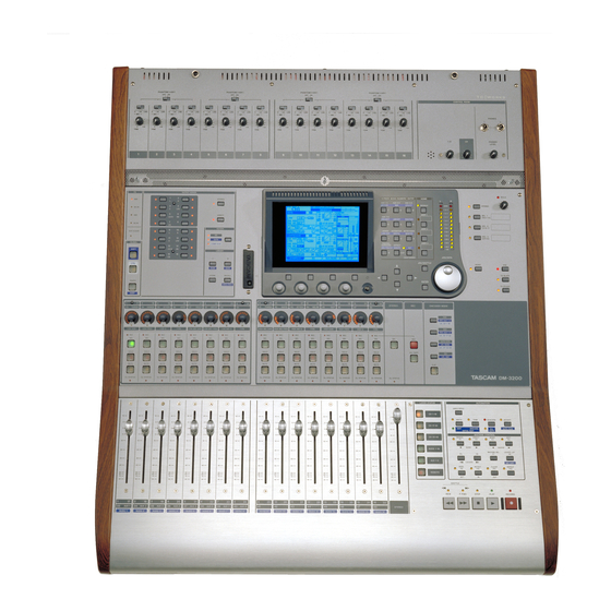
Sign In
Upload
Manuals
Brands
Tascam Manuals
Stereo Equalizer
DM-3200
Tascam DM-3200 Manuals
Manuals and User Guides for Tascam DM-3200. We have
7
Tascam DM-3200 manuals available for free PDF download: Owner's Manual, Manual, Release Notes, Software Manual, Application Manual, Quick Reference
Tascam DM-3200 Owner's Manual (120 pages)
Digital Mixing Console
Brand:
Tascam
| Category:
Music Mixer
| Size: 6.45 MB
Table of Contents
Important Safety Instructions
3
Table of Contents
4
1 Introduction
9
Computer (DAW) Integration
9
Other Key Points
9
Please Read this Manual
9
Figure 1.1: Basic Logical Components of the
10
Channel Destinations
11
Effects
11
Outputs
11
About the DM-3200
10
Inputs
10
Channel Modules
10
Unpacking the DM-3200
11
About the Manual
12
What's in the Manual
12
1, "Introduction
12
2, "Basic Operational Concepts
12
3, "Connections
12
4, "Routing & Assignment
12
5, "Channel Modules
12
6, "Effects
12
7, "MIDI
12
8, "Remote Operation
12
Special Notes for Touch-Sensitive Faders
13
Copyright, Etc
13
Figure 1.1: Overview of the DM-3200
14
Analog Input Section
15
Control Section
15
Encoder Section
15
Library Section and CF Card Slot
15
Machine Control Section
15
Modifier Section
15
Module & Layer Control Section
15
Monitoring Section
15
The Features of the DM-3200
14
Figure 2.1: Control Keys
16
Jumping to Commonly-Used Screens
17
Setting a USER Screen
17
2 Basic Operational Concepts
16
Smart Keys
16
What's on the Screen
16
Figure 2.2: Explanation of the Top Line of Screen Displays
17
Fader Layers
18
Figure 2.3: POD Controls
18
Special Controls
18
The Pods
18
Figure 2.9: POD Keys 2 and 4 Used to Jump to Other
19
Figure 2.8: POD Keys Used to Select Sub-Screens
19
Figure 2.7: POD 1 Used with a Pull-Up Menu List
19
Figure 2.6: POD Keys 2 through 4 Used as Soft Keys
19
Figure 2.5: POD Knob 4 Used as List Selector
19
Figure 2.4: POD Knobs Used in a Multi-Control Screen
19
Figure 2.10: Encoder Functions
20
Lvl Aux
21
Lvl Buss
21
Lvl Ch 1-16, 17-32, 33-48
21
Pan Aux 1-2
21
Reading the Encoder Indicators
21
Pan Settings
21
Encoders
20
Encoder Mappings
20
Pan Mode
20
Aux Mode
20
GATE/DYN Dynamics Processor Mode
20
Figure 2.11: Encoders in Pan Mode
21
Snd Aux 1-2
21
EQ Settings
22
Figure 2.12: Encoders in EQ Gain Mode
22
Figure 2.13: Encoders in EQ Frequency Selection Mode
22
Figure 2.14: Encoders in Frequency Q Adjustment Mode
22
Figure 2.17: ENCODER OPERATION Menu Item
23
Figure 2.16: Encoders Used to Make Module Level and Aux Send Adjustments
23
Figure 2.15: Encoders Used to Make Frequency Band Filter Type Selections
23
Module Levels and AUX Sends
23
The FLIP Key
23
Dynamics Settings
23
Encoder Behavior
23
Figure 2.18: Formatting a CF Card
24
CF Cards
24
Formatting a New Card
24
Figure 2.19: Shutting down the DM-3200
25
Figure 2.20: Powering up the DM-3200 with no Previous Shutdown
25
Shutting down the DM-3200
25
Important Caution
25
How to Shut down the DM-3200
25
Starting up the DM-3200
25
Figure 2.21: Project Structure
26
About Projects and Libraries
26
Figure 2.22: Setting the Date and Time
27
Figure 2.23: the NEW PROJECT Page
27
Setting the Date and Time
27
Creating a New Project
27
Using a Template
27
Figure 2.24: the Project Management Page
28
Managing Projects
28
Loading a Project
28
Copying a Project
28
Deleting a Project
28
Renaming a Project
28
Figure 2.25: Storing a Project
29
Saving Project Data
29
Figure 2.27: Library Selection Pull-Up Menu
30
Figure 2.26: Library Management (Gate Library Shown as Example)
30
Deleting Library Entries
31
Recalling Library Entries
31
Storing Library Entries
31
Viewing Library Entries
31
Library Management
30
Using Library Banks
30
Figure 2.28: Library Utility Screen
31
Source Parameters
32
Library Utilities
31
Target Parameters
31
Figure 2.29: Setting and Editing Titles and Memos
32
ENCODER OPERATION Mode
33
Fader Sensitivity
33
Library Direct Key Operation
33
LOCATE DISPLAY Mode
33
Ol/Status Led Type
33
Upper Bar Display
33
Naming Library Entries
32
Options
32
SETUP Screen
32
Figure 2.30: the SETUP Option Screen
33
Figure 2.31: Display Top Line Set to SYSTEM
33
Preferences
34
Fader Auto MODULE Select
34
CH solo Key Auto MODULE Select
34
Select MODULE Return
34
ST Link by SEL Key
34
SEL Key Follows Fader Layer Status
34
Meter Follows SEL Key
34
Automation Fader off
34
Balance Level Center:0Db
34
AUX Mute Follows CH Mute
34
BUSS Link/Buss PAN Are Linked
35
Figure 2.33: solo Options
35
Solo
35
Mode Select
35
Solo Link
35
Solo Type
35
Inplace solo Defeat
35
Figure 2.34: UTILITY Copy Screen
36
Utilities
36
UTILITY Copying
36
Figure 2.35: UTILITY External Switch Settings
37
SWITCH Utility
37
Talkback
37
Machine Control
37
Other Functions
37
Polarity
37
Figure 3.1: Overview of Rear Panel Features
38
Analog Connections
39
MIC/Line Connections
39
Channel Inserts
39
Assignable Returns
39
Figure 3.2: Analog Channel Inputs and Controls
39
Analog Outputs
40
Stereo out
40
Assignable Sends
40
Monitoring (STUDIO OUTPUTS)
40
ADAT "Lightpipe" out & in
40
Cascade
40
Digital Audio I/O
40
Digital Inputs and Outputs
40
Tdif I/O
40
Digital I/O Setup
41
Digital Inputs
41
Mute Defeat
41
Stereo Output
41
Digital Connections
40
Figure 3.3: DIGITAL SETUP Screen
41
Slot Card Configuration
42
Word Sync
42
If-An/DM
42
If-Ae/DM
42
If-Td/DM
42
If Ad/DM
42
Checking the Clock
44
Clock Change Action
44
Varispeed Clocking
44
Other Connections
42
To Meter
43
Foot Sw
43
Usb
43
Power Input
43
Figure 3.4: IF-AN/DM (at Left) and IF-AE/DM (at Right)
42
Figure 3.5: IF-TD/DM (at Left) and IF-AD/DM (at Right)
42
Clock Setting
44
Figure 3.7: Checking the Clock Sources
44
Figure 3.6: PROJECT CLOCK Screen (High-Speed)
44
Changing the Clock
45
Clock Phase
45
Out Speed
45
Figure 4.1: Module Facilities on the DM-3200
46
Input Routing
47
Figure 4.2: Routing Inputs
47
Routing & Assignment Routing
47
Batch Routing
48
Digital Input Selection
48
Flipping the Channels
48
Loopback Options
48
Output Routing
49
Slot Card Outputs
49
Figure 4.3: Routing Outputs
49
Insert Patching
50
Send/Return Linking
50
Figure 4.4: Routing Inserts
50
Channel-To-Buss Assignment
51
Assignment Using the Front Panel
51
Figure 4.5: Assignment Keys
51
Figure 4.6: Buss Assignment Screen (Linked Busses)
51
Figure 4.7: Buss Assignments with the Pan Switch off
52
Bulk Assignment
53
Buss Panning
53
Non-Channel Assignments
53
Surround Assignments
53
Using the Assignment Screens
51
Pan Switch
52
Figure 4.8: Surround Channel Assignment Screen
53
Monitoring
54
Selecting the CR Source
54
Figure 4.9: Monitoring and Metering Controls
54
Studio Cue Source
55
Figure 4.10: Monitor Parameters Screen
55
Talkback, Etc
56
Talkback Source
56
Slate Definition
56
Figure 4.11: Monitor Oscillator and Communication
56
Oscillator and Noise Generator
56
Oscillator Destination
56
Figure 4.12: Metering Screen (1St 24 Channel Module Meters)
57
Meter Ballistics
57
Metering Points
57
Soloing
58
Figure 5.1: Assign Parameters Screen
59
COMP/EXP Display and COMP Button
60
Compressor/Expander Point Button
60
EQ Display and Button
60
Fader
60
GATE Display and Button
60
Input and Return Display
60
Meters and Pick-Off Point Button
60
MUTE Button
60
PAN (BALANCE) Control
60
PAN Follow Button
60
AUX1-2 Button
61
Group Assignment Displays
61
STEREO Button
61
General Principles
59
Figure 5.3: Channel Fader Screen
61
Figure 5.4: Master Fader Screen
61
Fader Control
61
Master Screen
61
Figure 5.5: Unlinked DYNAMICS Screen (Channels 1 through 32)
62
Figure 5.6: Linked DYNAMICS Screen (Channels 1 through 32)
62
Dynamics Processors
62
Link
62
Trigger Mode ( TRG MOD )
62
Trigger Selection
62
Turning the Processors on and off
62
Gates (Input Channels 1–32)
63
Gate Attack Time
63
Hysteresis ( HYST )
63
Gate Decay Time (DECAY)
63
Compressor/Expanders
63
Comp/Expand
63
Insert Point ( ins PNT )
63
Threshold
63
Compression/Expansion Ratio
63
Release Time
63
Auto Make-Up
64
Output Gain
64
Library Jump Buttons
64
Preset Dynamics Library Entries
64
Compressor/Expander Library Entries
64
Figure 5.9: Assigning Dynamics Processor Triggers
65
Gate Library Entries
65
Table 5.8: Gate/Expander Preset Library Entries
65
Encoders and EQ
66
Trigger Settings
65
Figure 5.10: Module EQ Screen
66
EQ Library
67
Figure 5.11: EQ Library
67
Table 5.12: EQ Library Presets
67
Aux and Buss Setup
68
Aux Send Screens (Unlinked)
68
Batch Setting
68
Copying Settings between Aux Sends and Channel Levels
68
Figure 5.14: Aux Send Screen (Unlinked)
68
Figure 5.13: Module Aux and Buss Screen
68
Aux Send Pan/Balance Screens (Linked)
69
Source Selection
69
Using the Encoders
69
Figure 5.15: Aux Pan/Balance Screen (Linked)
69
Module Setup
70
Assignable Insert Position
70
Aux 1-2 Source
70
Dynamics Insert Point
70
Dynamics On/Off
70
Figure 5.16: Channel Module SETUP Screen
70
GATE Switching
70
INPUT/RETURN Selection
70
Module Delay
70
Phase Control
70
Digital Trim
71
Dithering (Stereo Buss Module Only)
71
Figure 5.18: Linked Pair Balance Controls
71
Figure 5.20: Channel Delay Screen
72
Figure 5.21: Master Delay Screen
72
Stereo Linking
72
Balance
73
Linked Dynamics
73
Figure 5.19: Digital Trim Setting
71
Pan and Balance Settings
71
Phase/Trim/Delay
71
Phase
71
Delay
72
Figure 5.24: Mute Grouping
73
Figure 5.23: Stereo Linking Screen
73
Figure 5.22: Linking Modules
73
Mute Groups
73
Clearing Groups
74
Fader Groups
74
Grouping Groups
74
Linking Fader Groups to Mute Groups
74
Figure 5.25: Clearing a Group
74
Figure 5.26: Grouping Groups
74
Figure 5.27: Fader Grouping
74
Surround Operations
75
Assigning Channels to Surround Busses
75
Changing Surround Mode
75
Buss Assignments
75
Figure 5.28: Selecting Surround Mode
75
Table 5.29: Buss Assignments in Surround Mode
75
Figure 5.32: Module Surround Panning
76
Figure 5.30: Surround Assignment
76
Figure 5.35: LFE Level
78
Figure 5.34: Surround Screen (Pan Mode Off)
78
LFE Level
78
Pan Mode off
78
Figure 5.31: Surround Overview
76
Surround Panning
76
Module Screen
76
Figure 5.33: Surround Panning (Pan Mode On)
77
Jump Keys
77
Pattern Panning
77
Using the Cursor Keys
77
Snapshots
79
Figure 5.36: Snapshot Library
79
Snapshot Library Management
79
Figure 5.37: Storing a Snapshot
80
Information about a Snapshot
80
Storing Snapshots
80
Figure 6.1: Internal Effect Send and Return Routing
81
Figure 6.2: Effect Library Screen
81
TASCAM Effect Parameters
82
6 Effects
81
Routing the Effects
81
Effects Routing the Effects
81
Setting up the Effects
81
Table 6.5: TASCAM Effect Parameters
82
Figure 6.4: Common Effect Parameters (Row 1)
82
Table 6.6: TC Reverb Effect Parameters
83
Table 6.7: Preset TC Reverb Effects
84
Preset TASCAM Effects
87
Figure 6.3: Effect Setting
82
TC Works Effect Parameters
83
Effect Libraries
84
Preset TC Reverb Effects
84
Table 6.8: TASCAM Effects
87
Figure 7.1: MIDI Setup
91
7 MIDI
91
MIDI Port Switching and Filtering
91
Figure 7.2: MIDI Program Change Screen
92
Program Change Messages and the DM-3200
92
Setting the MIDI Channels
92
Batch Setup
92
MIDI Implementation Charts
92
DM-3200
93
Figure 8.1: Adding External Devices for Control by the
93
Table 8.2: Control Methods
93
Devices
93
Deleting Devices from the List
94
Auto-Detection of Devices
94
Selecting the Control Type for the Devices
94
State
94
Device
94
Chase
95
Tra
95
Rec
95
All Safe
95
Transport Mapping Memories
95
To Use a Transport Mapping
96
Viewing the Transport Mappings
96
Editing a Mapping
96
8 Remote Operation Selecting Devices for Transport Control
93
Figure 8.4: Machine Control Setup Parameters
97
Locate Preroll
98
Record Command Type
98
Machine Control Setup
97
Edit Frames
97
Cueing Mode
97
Play Mode
97
Auto
97
Deferred
97
Immediate
97
Play Command Type
97
Location Memories
99
Selecting the Location Point Display
99
Storing a Location Memory "On the Fly
99
Manually Entering and Editing a Location Memory
99
Location to a Location Memory
99
Viewing a List of Location Memories
100
Manual Location
100
Repeat Play
100
Auto Punch Operations
101
ALL INPUT and AUTO MON
101
9 Specifications
102
Analog Audio I/O
102
Digital Audio I/O
103
Miscellaneous I/O Connections
103
Equalization
104
System Performance
104
Physical Characteristics
104
Figure 9.1: Dimensional Drawing
105
Table 9.2: Popup Messages
105
Dimensional Drawing
105
Messages and Troubleshooting
105
Figure 9.3: Block Diagram
116
Block Diagram
116
Figure 9.4: Level Diagram
117
Level Diagram
117
Advertisement
Tascam DM-3200 Manual (36 pages)
Digital Mixing Console
Brand:
Tascam
| Category:
Music Mixer
| Size: 0.4 MB
Table of Contents
Table of Contents
2
1 Introduction
4
Using this Manual
4
Automated Controls
4
A Note on Touch-Sensitive Faders
5
Setup
5
Timecode
5
Mtc
5
Figure 1: Timecode Source Selection (Showing USB MTC Selected)
5
2 Starting out with the Timecode
6
Access the Automation Screens
6
Turn on the Automation
6
Figure 2: the Automation FILES Display
6
Figure 3: Automation SETUP Screen
6
Make the Initial Settings
7
Store the Current Settings
7
Write some Fader Moves
7
Write some Mute Moves
7
Figure 4: Naming a MIX
7
Write some Aux Send Moves
8
Writing Encoder or POD Moves
8
Trimming Existing MIX Moves
8
Finishing up
8
3 Automation Overview
9
Modes
9
Auto
9
Write
9
Trim
10
Static
10
Safe
10
Off
10
Figure 5: Illustration of Trim Mode Behavior
10
Rehearse
11
Displays
11
Auto Setup
11
Automation Engine
11
Auto Store
11
Keep Confirmation
11
Automation Mode Multi Pass
11
Figure 6: AUTO SETUP Screen
11
Trim All
12
Auto Revert
12
Revert Times
12
Control Sense Time out
12
Auto Fade out Time
12
TOUCH Function
13
Auto Files
13
Top Line
13
Figure 7: AUTO FILES Screen
13
Auto Config
14
Module
14
All Module
14
All Cntrls
14
All
14
Copy
14
Paste
14
REVERT Key
14
Figure 8: AUTO CONFIG Display
14
Undo/Redo
15
Channel LED Indicators
15
4 Operation
16
Setting up Your MIX
16
Action
16
Result
16
Writing MIX Moves
16
Revert Time
16
Auto Revert Choices
16
Figure 9: Writing a Fader Move over a Previous Static Fader Position with Auto Revert Enabled
17
Figure 10: Writing a POD (or Encoder) Move over a Previous Static Position with Auto Revert Enabled
17
Figure 11: Writing a New Fader Move over a Previous Dynamic Fader Move with Auto Revert Enabled
18
Figure 12: Writing a New POD (or Encoder) Move over a Previous Dynamic Move with Auto Revert Enabled
18
Disabling Auto Revert
19
Figure 13: Writing a New Fader Move over a Previous Static Fader Position with Auto Revert Disabled
19
Figure 14: Writing a New POD or Encoder Move over a Previous Static Position with Auto Revert Disabled
19
Figure 15: Writing a New Fader Move over Previous Dynamic Fader Moves with Auto Revert Disabled
20
Figure 16: Writing a New POD or Encoder Move over Previous Dynamic Moves with Auto Revert Disabled
20
Write to End
21
Figure 17: Write to End over Previous Static Fader Position
21
Figure 18: Write to End over Previous Dynamic Fader Moves
21
Figure 19: Write to End over Previous Static POD or Encoder Position
22
Figure 20: Write to End over Previous Dynamic POD or Encoder Moves
22
Writing Switch Events
23
Action
23
Result
23
Revert Time
23
CONTROL SENSE TIME out & Switch Events
23
Auto Revert Choices
24
Figure 21: Writing New Switch Events over Previous Switch Events with Auto Revert Enabled
24
Figure 22: Writing New Switch Events over Previous Switch Events with Auto Revert Disabled
25
Write to End
26
Figure 23: Writing a New Switch Event with Write to End Enabled
26
Trimming MIX Moves
27
Action
27
Result
27
Trim All
27
Revert Time
27
Auto Revert Choices
28
Figure 24: Trimming Fader Moves with Auto Revert Enabled
28
Figure 25: Trimming POD and Encoder Moves with Auto Revert Enabled
28
Figure 26: Trimming Fader Moves with Auto Revert Disabled
29
Figure 27: Trimming POD and Encoder Moves with Auto Revert Disabled
29
Trim to End
30
Figure 28: Trimming Fader Moves with Trim to End Enabled
30
Figure 29: Trimming POD and Encoder Moves with Trim to End Enabled
30
Initial Status
32
Editing the Initial Status
32
Figure 30: Initial Status and Dynamic Data
32
Figure 31: Initial Status Editing
33
Automating Library Recall
34
Writing Library Recall Events over Existing Static Control Positions
34
Combining Library Recall with Dynamic MIX Moves
34
Automating Groups
35
Grouping Non-Automated Controls
35
Grouping Automated Controls
35
Hierarchical Groups
35
MIX File Management
35
The MIX Data
35
Tascam DM-3200 Release Notes (26 pages)
V 1.50
Brand:
Tascam
| Category:
Music Mixer
| Size: 1.13 MB
Table of Contents
Table of Contents
2
Manual Addendum
3
New Features
3
New Features in V 1.50
3
User Defined Layer
3
Registering a User Defined Layer
3
User Defined Layer Screen
3
MUTE Key Function
4
Meter Display
4
TASCAM FX2.0 Recall
5
TASCAM FX2.0 Support
5
TASCAM FX Compressor GR Meter Indication
5
DAW Control Screen Display of Channels 1-16
6
Windows Vista
6
New Features in V1.30
6
IF-FW MKII Support
6
TDIF Hi-Speed Support
6
MIDI
7
MIDI Control Change Message Support for Mixer Parameters
7
MIDI>SETUP Screen Filtering
7
Operation
8
Module Parameter Copy Function
8
BUSS Pan Mode Batch Setup
8
Meter Over-Level Settings
9
Cursor Location When a Multi-Control
9
Screen Is Displayed
9
MUTE Clear Function Has Been Added
9
Automation WR-RHS Indication Has Been Added
9
About Remote Control
9
Use P2 Protocol to Remotely Control the X-48
9
Scrolling Indicators for the Supported Device List in the Machine Control Screen
10
MMC Command Type Added
10
Transmission of Locate Commands When Editing a Locate Point
10
New Features in V 1.20
10
Firewire Card Support
11
Surround Monitor Card Support
11
Naming the Mixer
11
Remote Operation through MMC
12
MIDI Control
12
Connection
13
Setting Devices for MIDI Control
13
Selecting Devices for MIDI Control
13
Selecting Control Types for the Devices
13
Setting up Individual Devices
13
MIDI Controllers
14
MIDI Fader
14
MIDI Mixer
15
Changing the Assignment
15
Assigning Parameters to Rotary Encoders
16
Cascade Connection
16
Cascade Connection Overview
16
Master/Slave Setting
16
Making a Cascade Connection
17
Settings and Operations that Can be Interlocked
18
Settings that Can be Interlocked
18
Operations that Can be Interlocked
18
GPI Functionality
18
Making Connections
18
Setting the GPI
19
GPI CONFIG Section
19
TIME EVENT Section
20
Editing the GPI EVENT LIST
20
Expanded Dynamic Automation Function
21
Additional Dynamic Automation Parameters
21
Additional Parameters that Are Re-Played as Initial Status
21
Settings Prohibited to Change During Automation Re-Play
21
New Feature in V 1.10
22
Maintenance Items
23
Maintenance Items in V1.50
23
V1.50 Remote Control
23
Maintenance Items in V1.30
23
Change in the Date Information for Project Property
23
CF Cards
23
Project
23
Create Project
23
Load Project
23
V1.30 Remote Control
23
Switching of BUSS PAN Follows ST PAN During Automation Is Now Disabled
24
Slave Lock Processing When Cascade Connection Is Cancelled
24
STORE Button in the Library/Automation LCD Screen
24
Maintenance Items in V1.20
24
DTRS REC Function Setting in P2
24
MX-2424 REC Function Setting Via MMC
24
Known Issues
25
Known Issues in V1.50
25
DTRS REC FUNCTION Setting When Controlling Via P2
25
Auto Detection of MMC Control Target
25
Updating the Firmware on a Cascaded Mixer
25
USB Connection Notes
25
Advertisement
Tascam DM-3200 Release Notes (20 pages)
Brand:
Tascam
| Category:
Music Mixer
| Size: 1.17 MB
Table of Contents
Table of Contents
2
Firmware Update Notice
3
Manual Addendum
3
New Features
3
Version 1.50
3
User Defined Layer
3
TASCAM FX2.0 Support
4
TASCAM FX Compressor GR Meter Indication
5
DAW Control Screen Display of Channels 1-16
5
Windows Vista
5
Version 1.30
6
IF-FW MKII Support
6
MIDI
6
Operation
7
Automation WR-RHS Indication Has Been Added
8
About Remote Control
8
Firewire Card Support
9
Surround Monitor Card Support
9
Naming the Mixer
9
Version 1.20
9
Remote Operation through MMC
10
MIDI Control
10
MIDI Controllers
11
MIDI Fader
11
MIDI Mixer
12
Assigning Parameters to Rotary Encoders
12
Cascade Connection
13
Making a Cascade Connection
13
GPI Functionality
14
Expanded Dynamic Automation Function
16
Version 1.10
17
Maintenance Items
17
Version 1.60
17
Option Slot Cards
17
Remote Control
17
When Connected to Tmcompanion
17
Monitor Section
17
Project
17
Operation
17
Factory Default Settings
17
Version 1.50
18
V1.50 Remote Control
18
Version 1.30
18
Change in the Date Information for Project Property
18
CF Cards
18
Project
18
V1.30 Remote Control
18
Switching of BUSS PAN Follows ST PAN During Automation Is Now Disabled
18
Slave Lock Processing When Cascade Connection Is Cancelled
18
STORE Button in the Library/Automation LCD Screen
19
Version 1.20
19
Known Issues
19
Version 1.60
19
DTRS REC FUNCTION Setting When Controlling Via P2
19
Auto Detection of MMC Control Target
19
USB Connection Notes
19
Multiple IF-AE/DM Cards and Clock Master
19
Tascam DM-3200 Software Manual (8 pages)
Digital Mixing Console
Brand:
Tascam
| Category:
Music Mixer
| Size: 1.33 MB
Table of Contents
Table of Contents
2
1 Introduction and Installation
3
Installation (Windows)
3
Repairing and Uninstalling Tmcompanion
4
Installation (Mac os X)
4
Uninstalling Tmcompanion
4
Copyright, Etc
4
2 Using Tmcompanion
5
Backup and Restore
5
Timecode/Transport Window
6
Meter Bridge
6
Firmware Update
7
Screen Shot
7
3 Preferences
8
MIDI Time Code
8
Window Settings
8
Confirmations
8
Settings
8
Tascam DM-3200 Application Manual (4 pages)
32-channel Digital Mixing Console
Brand:
Tascam
| Category:
Music Mixer
| Size: 0.39 MB
Tascam DM-3200 Quick Reference (2 pages)
Tascam Stereo Equalizer - EQ User Manual
Brand:
Tascam
| Category:
Stereo Equalizer
| Size: 1.57 MB
Advertisement
Related Products
Tascam DM-24
Tascam DM-4800
Tascam DV-D01U
Tascam DA-40
Tascam DP-008EX
Tascam DP-32 Digital Portastudio
Tascam DR-60D
Tascam DP-24SD
Tascam DR-40X
Tascam DR-05X
Tascam Categories
Recording Equipment
Music Mixer
Voice Recorder
CD Player
Accessories
More Tascam Manuals
Login
Sign In
OR
Sign in with Facebook
Sign in with Google
Upload manual
Upload from disk
Upload from URL