Sign In
Upload
Manuals
Brands
Symmetricom Manuals
Receiver
TimeSource 3100
Symmetricom TimeSource 3100 Manuals
Manuals and User Guides for Symmetricom TimeSource 3100. We have
2
Symmetricom TimeSource 3100 manuals available for free PDF download: User Manual
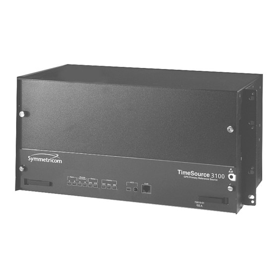
Symmetricom TimeSource 3100 User Manual (200 pages)
GPS Primary Reference Source
Brand:
Symmetricom
| Category:
GPS
| Size: 2 MB
Table of Contents
Table of Contents
3
How to Use this Guide
11
Chapter 1 Overview of the Timesource 3100
17
Overview
18
Global Positioning System
18
Physical Description
18
Timesource 3100 Shelf
19
Roof Antenna
20
Functional Description
20
Overview
20
The GPS Antenna
20
Block Diagram of the Timesource 3100
21
Timing Source Characteristics
21
Antenna
22
IF Interface
22
Local Oscillator
22
Clock Extractors
22
Power Supply
22
NTP Timeserver
22
Network Time Protocol Password Activation
23
Bestime Ensemble Timing Generator
23
E1 or Analog Outputs
23
Eight Mixed E1/T1 Outputs (990-72020-06 Systems Only)
23
Eight Additional E1 Outputs (990-72020-02 Systems Only)
24
TOD Output
24
IRIG-B TOD Outputs (990-72020-05 Systems Only)
24
PPS Output
24
10 Mhz Output
24
Two ESCIU Ports (990-72020-04 Systems Only)
24
Alarm Interface
25
Communications Ports
25
Ethernet
25
Passthrough
25
ESCIU Signals
25
Alarm Programmability
26
Timesource 3100 Passthrough Function
26
Startup
27
Bridging/Holdover Behavior
28
Time Figure of Merit
29
Chapter 2 Engineering & Ordering
31
Site Survey
32
Lightning Suppressor Guidelines
33
Antenna Location Guidelines
33
Locating the GPS Antenna
34
GPS Antenna Location Examples
35
Earth Ground Location Guidelines
36
Sample Rooftop Antenna Mounting
36
Antenna Cable Choices
37
Remote Oscillator Cabling
38
Isolation Kits for DCD Shelves
38
IRIG-B TOD (990-72020-05 Systems Only)
39
RJ-422-To-RJ-232 TOD Converter
39
Shelf Considerations
39
Systems
40
Standard System (Two E1 or 2.048 Mhz Outputs)
40
Rack Mounting Options
40
With Eight Additional E1 or 2.048 Mhz Outputs
41
With Eight Additional Mixed E1/T1Outputs
41
With Two E1 Synchronization Insertion (ESCIU) Ports
42
With Four IRIG-B TOD Outputs
42
User-Supplied Tools and Materials
43
For Antenna Installation
43
For Shelf Installation
43
Outputs, Power, and Miscellaneous
43
Chapter 3 Installing the Timesource 3100
45
Unpacking the Unit
46
Installing the Antenna
47
Antenna-To-Shelf Cabling
47
Installing the Antenna Bracket on a Pipe
48
Installing the Antenna Bracket on a Post
48
Attaching the Antenna to the Bracket
49
Assembling the Lightning Suppressor
50
Installing the Shelf
51
Installing Output Modules
51
Rack Mounting
52
Location of the Options I/O Connector
52
Making Cable Connections
53
Rack Mounting Options
53
Frame Ground
54
Connector Panel and Front Panel Connectors
54
Terminal Block Connections on the Connector Panel
55
Making Power Connections
56
Making GPS Antenna Connections
56
Making 10 Mhz Output Connections
56
Making E1 or Analog Synchronization Output Connections
57
Making 1 PPS Output Connections
57
E1 or Analog Output Wire-Wrap Connections
57
Connecting E1 or Analog Reference Inputs
58
Connecting Remote Oscillator Inputs
58
E1 or Analog Output Wire-Wrap Connections
58
DCD Connections to the Timesource 3100
59
DCD Shelf, Isolation Module, and Timesource 3100 Connections
60
Installing a Module for Additional E1 or Analog Outputs
61
Eight E1 or Analog Output Connections
61
Installing the Mixed E1/T1 Output Module
62
Installing the IRIG-B TOD Output Module
62
Eight Mixed E1/T1 Output Connections
62
Installing the ESCIU Port Module
63
IRIG-B TOD Output Connections
63
Connector Layout of ESCIU Modules
64
ESCIU Cutover Without Jacks (Out-Of-Service)
65
ESCIU Cutover with Jacks (In-Service)
67
Connecting the Time of Day Output
68
TOD Connector Pinout
68
Converter DB-25 Connector Pinout
69
RS-422 to RS-232 TOD Converter Mounting Plate
69
Making Ethernet Connections
70
Connecting to Communication Port 1
70
Ethernet RJ-45 Connector Pinout
70
COM 1 Connector Pinout
70
Connecting to Communication Port 2
71
Connecting Alarm Outputs
71
COM 1 Connector Pinout
71
Making Craft Port Connections
72
Alarm Connector
72
COM 1 Connector Pinout
72
Powering up the Shelf
73
Installing Timewizard
81
The Timewizard Main Screen
82
The Download Gps.hex Screen
83
The Load GPS File Dialog Box
84
The Download Progress Dialog Box
84
The Status Information Screen
86
The Set the Alarm Parameters Screen
87
Alarm Parameters
87
The View the Alarm Parameters Window
88
The Exit Application Window
89
Factory Default Values
90
The Save Log File Dialog Box
90
Parameter Factory Settings
90
Chapter 4 TL1 Reference
93
Conventions
94
Command Format
94
Response Format
95
Command Format
95
Completed Response Format
95
Parameters
96
Deny Response Format
96
Parameter Definitions
96
Autonomous Messages
99
Report Alarm
99
Report Event
99
Tasks/Commands
100
Commands for Tasks
100
Commands
101
Activate User
102
Cancel User
103
Copy Memory
104
Delete Equipment
106
Delete User Security
107
Edit Communication
108
Edit Date
111
Edit Equipment
113
Alarm Conditioning Flow Chart
121
Enter Equipment
122
Enter User Security
124
Initialize Log
125
Initialize Register
126
Initialize System
127
Operate Alarm Cutoff All
128
Retrieve Alarm All
129
Retrieve Alarm Equipment
130
Retrieve Communication
131
Retrieve Condition All
134
Retrieve Condition Equipment
135
Retrieve Equipment
136
Retrieve GPS Status
143
Retrieve Header
144
Retrieve Inventory
145
Retrieve Log
147
Retrieve Performance Monitoring
148
Retrieve User Security
157
Set Source Identifier
158
Chapter 5 Troubleshooting
159
Troubleshooting with Front Panel Items
160
Controls and Indicators
160
Front Panel Items
161
Troubleshooting with Error Messages
164
Message Troubleshooting
164
Replacing Cards
170
Returning the Timesource
171
Front of Shelf
171
Repacking the Unit
172
Equipment Return Procedure
172
User Guide Updates
173
Chapter 6 Specifications
175
Antenna
176
Communication Ports
176
Port 1
176
Port 2
177
Craft Port
177
Ethernet Port
178
Time of Day Outputs
179
Network Time Protocol (NTP) Type 4, Format 2 Driver Format
179
NTP Type 4 Data Format
179
Cisco Systems Format
180
NTP Type 4 Data Format
180
IRIG-B TOD Outputs (990-72020-05 System Only)
181
Remote Oscillator Inputs
181
E1 Inputs
182
Analog 2.048 Mhz Inputs
183
PPS Output
184
E1 Outputs
185
Standard
185
Additional E1 Outputs (990-72020-02 System Only)
186
Analog 2.048 Mhz Outputs
187
Standard
187
Additional Analog Outputs (990-72020-02 System Only)
188
Mixed E1/T1 Outputs (990-72020-06 System Only)
189
E1/T1 Common
189
E1 Outputs
189
T1 Outputs
190
10 Mhz Output
190
ESCIU Ports (990-72020-04 System Only)
191
Office Alarms
192
Connector Panel Contacts
192
Front Panel Lamps
192
Front Panel Control
192
Simple Network Time Protocol
193
Power
193
Shelf Mechanical
194
Shelf Environmental
194
Advertisement
Symmetricom TimeSource 3100 User Manual (238 pages)
GPS Primary Reference Source
Brand:
Symmetricom
| Category:
Receiver
| Size: 3 MB
Table of Contents
Table of Contents
5
Contents 097-72020-01 Issue 9: November
10
Chapter 1 Description
11
Overview
12
Global Positioning System
13
Physical Description
14
Roof Antenna
16
Functional Description
17
Overview
17
Antenna
19
IF Interface
19
Local Oscillator
19
Clock Extractors
20
Power Supply
20
NTP Timeserver
20
Network Time Protocol Password Activation
20
Bestime Ensemble Timing Generator
20
E1 or Analog Outputs
21
Eight Mixed E1/T1 Outputs (990-72020-06 Systems Only)
21
Eight Additional E1 Outputs (990-72020-02 Systems Only)
21
TOD Output
21
IRIG-B TOD Outputs (990-72020-05 Systems Only)
21
PPS Output
21
10 Mhz Output
22
Two ESCIU Ports (990-72020-04 Systems Only)
22
Alarm Interface
22
Communications Ports
22
Ethernet
23
Passthrough
23
Alarm Programmability
24
Startup
24
Bridging/Holdover Behavior
25
Time Figure of Merit
26
Chapter 2 Engineering & Ordering
29
Site Survey
30
Lightning Suppressor Guidelines
31
Antenna Location Guidelines
32
Earth Ground Location Guidelines
35
Antenna Cable Choices
36
Remote Oscillator Cabling
37
IRIG-B TOD (990-72020-05 Systems Only)
38
RJ-422-To-RJ-232 TOD Converter
39
Shelf Considerations
40
Systems
41
Standard System (Two E1 or 2.048 Mhz Outputs)
41
With Eight Additional E1 or 2.048 Mhz Outputs
42
With Eight Additional Mixed E1/T1Outputs
43
With Two E1 Synchronization Insertion (ESCIU) Ports
44
With Four IRIG-B TOD Outputs
45
User-Supplied Tools and Materials
46
For Antenna Installation
46
For Shelf Installation
46
Outputs, Power, and Miscellaneous
47
Chapter 3 Installation
49
Unpacking
50
Antenna
51
Shelf
56
Output Module Installation
56
Rack Mounting
57
Cabling
58
Frame Ground
60
Power
61
GPS Antenna
61
10 Mhz Output
61
E1 or Analog Synchronization Outputs
62
PPS Output
63
E1 or Analog Reference Inputs
63
Remote Oscillator Inputs
64
Module for Additional E1 or Analog Outputs
67
Module for Mixed E1/T1 Outputs
68
Module for IRIG-B TOD Outputs
69
Module for ESCIU Ports
70
Cutover Procedures for Out-Of-Service Equipment
71
Timesource
72
Cutover Procedures for In-Service Equipment
73
Time of Day Output
75
Ethernet
78
Communication Port 1
79
Communication Port 2
80
Alarms Output
81
Craft Port
82
Power-Up
83
Timewizard
91
Factory-Set Values
105
Chapter 4 TL1 Reference
109
Conventions
110
Command Format
111
Response Format
112
Parameters
113
Autonomous Messages
116
Report Alarm
117
Report Event
118
Tasks/Commands
119
Commands
121
Activate User
122
Cancel User
123
Copy Memory
124
Delete Equipment
126
Delete User Security
127
Edit Communication
128
Edit Date
131
Edit Equipment
134
Enter Equipment
141
Enter User Security
143
Initialize Log
144
Initialize Register
145
Initialize System
146
Operate Alarm Cutoff All
147
Retrieve Alarm All
148
Retrieve Alarm Equipment
149
Retrieve Communication
151
Retrieve Condition All
154
Retrieve Condition Equipment
155
Retrieve Equipment
157
Retrieve GPS Status
164
Retrieve Header
166
Retrieve Inventory
167
Retrieve Inventory (Cont'D)
168
Retrieve Log
169
Retrieve Performance Monitoring
170
Retrieve User Security
183
Set Source Identifier
184
Chapter 5 Troubleshooting
185
Troubleshooting with Front Panel Items
186
Troubleshooting with Error Messages
190
Card Replacement
196
Repair and Return
198
Technical Assistance
200
Sales
200
Manual Updates
201
Chapter 6 Specifications
203
Antenna
204
Communication Ports
205
Port 1
205
Ethernet Port
208
Time of Day Outputs
209
Network Time Protocol (NTP) Type 4, Format 2 Driver Format
209
Time of Day Outputs (Cont'D)
210
Cisco Systems Format
210
Time of Day Outputs (Cont'D)
211
IRIG-B TOD Outputs (990-72020-05 System Only)
211
Remote Oscillator Inputs
212
E1 Inputs
213
Analog 2.048 Mhz Inputs
214
PPS Output
215
E1 Outputs
216
Standard
216
Additional E1 Outputs (990-72020-02 System Only)
217
Timesource
217
Analog 2.048 Mhz Outputs
218
Standard
218
Additional Analog Outputs (990-72020-02 System Only)
219
Mixed E1/T1 Outputs (990-72020-06 System Only)
220
E1/T1 Common
220
E1 Outputs
220
Mixed E1/T1 Outputs (Cont'D)
221
T1 Outputs
221
10 Mhz Output
222
ESCIU Ports (990-72020-04 System Only)
223
Office Alarms
224
Connector Panel Contacts
224
Front Panel Lamps
224
Front Panel Control
224
Simple Network Time Protocol
225
Power
226
Shelf Mechanical
226
Shelf Environmental
226
Advertisement
Related Products
Symmetricom TimeSource 3600
Symmetricom TimeSource 3000
Symmetricom TimeSource 2700
Symmetricom TimeSource 500
Symmetricom TimeSource 2500
Symmetricom ET6000
Symmetricom ET6010
Symmetricom ET6500-OCXO
Symmetricom ET6500-RB1
Symmetricom ET6500-TCXO
Symmetricom Categories
Test Equipment
Clock
Receiver
Server
GPS
More Symmetricom Manuals
Login
Sign In
OR
Sign in with Facebook
Sign in with Google
Upload manual
Upload from disk
Upload from URL