Table of Contents
Advertisement
Quick Links
See also:
User Manual
Advertisement
Table of Contents
Troubleshooting

Related Manuals for Symmetricom TimeSource 3100


Summary of Contents for Symmetricom TimeSource 3100
- Page 1 TimeSource 3100 GPS Primary Reference Source User Guide Revision K – December 2005 Part Number 097-72020-01...
- Page 2 2300 Orchard Parkway San Jose, CA 95131-1017 U.S.A. http://www.symmetricom.com Copyright © 2003–2005 Symmetricom, Inc. All rights reserved. Printed in U.S.A. All product names, service marks, trademarks, and registered trademarks used in this document are the property of their respective owners.
-
Page 3: Table Of Contents
How to Use This Guide Chapter 1 Overview of the TimeSource 3100 Overview ............18 Global Positioning System . - Page 4 Outputs, Power, and Miscellaneous ....... . . 43 Chapter 3 Installing the TimeSource 3100 Unpacking the Unit.
- Page 5 Repacking the Unit ..........172 097-72020-01 Revision K – December 2005 TimeSource 3100 User’s Guide...
- Page 6 Shelf Environmental ..........194 TimeSource 3100 User’s Guide...
- Page 7 TimeSource 3100 Shelf ........
- Page 8 List of Figures viii TimeSource 3100 User’s Guide 097-72020-01 Revision K – December 2005...
- Page 9 Isolation Kits for DCD Shelves ........38 DCD Connections to the TimeSource 3100 ......59 TOD Connector Pinout .
- Page 10 List of Tables TimeSource 3100 User’s Guide 097-72020-01 Revision K – December 2005...
-
Page 11: How To Use This Guide
Structure of This Guide Conventions Used in This Guide Warnings, Cautions, Recommendations, and Notes Related Documents and Information Where to Find Answers to Product and Document Questions What’s New in This Document 097-72020-01 Revision K – December 2005 TimeSource 3100 User’s Guide... - Page 12 How to Use This Guide Purpose of This Guide The TimeSource 3100 User’s Guide describes the procedures for unpacking, installing, using, maintaining, and troubleshooting the Symmetricom TimeSource 3100. Who Should Read This Guide Chapter 1, Overview of the TimeSource 3100, and Chapter 2, Engineering &...
- Page 13 Warnings, Cautions, Recommendations, and Notes Warnings, Cautions, Recommendations, and Notes attract attention to essential or critical information in this guide. The types of information included in each are explained in the following examples. 097-72020-01 Revision K – December 2005 TimeSource 3100 User’s Guide xiii...
- Page 14 Note: All notes use this symbol. Notes contain installation, operation, or maintenance procedures, practices, conditions, or statements, that alert you to important information, which may make your task easier or increase your understanding. TimeSource 3100 User’s Guide 097-72020-01 Revision K – December 2005...
- Page 15 Where to Find Answers to Product and Document Questions For additional information about the products described in this guide, please contact your Symmetricom representative or your local sales office. You can also contact us on the web at www.symmetricom.com. What’s New in This Document This guide includes the following new topics: Reformat of the User Guide using more-legible fonts and navigation aids.
- Page 16 How to Use This Guide TimeSource 3100 User’s Guide 097-72020-01 Revision K – December 2005...
-
Page 17: Chapter 1 Overview Of The Timesource 3100
Chapter 1 Overview of the TimeSource 3100 This chapter provides an overview of the global positioning system, and a physical and functional description. In This Chapter Overview Physical Description Roof Antenna Functional Description 097-72020-01 Revision K – December 2005 TimeSource 3100 User’s Guide... -
Page 18: Overview
12, are in view anywhere in the world at all times. The TimeSource 3100 tracks all satellites within its field of view. The performance of each tracked satellite is observed and compared to the others, and available for use in the timing solution. -
Page 19: Timesource 3100 Shelf
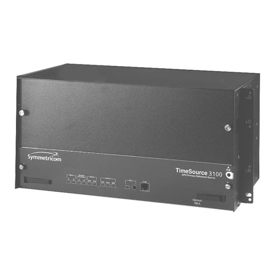
Chapter 1 Overview of the TimeSource 3100 Physical Description The shelf (Figure 1-1) can be mounted in a 48 cm rack or an ETSI 53.5 cm rack. Other than a communications connector on the front panel, all connectors are at the connector panel. -
Page 20: Roof Antenna
Functional Description Overview Figure 1-3 shows the main functions of the TimeSource 3100. The center of the TimeSource 3100 is the Ensemble Timing Generator, which uses the BesTime algorithm to analyze the phase and frequency relationships, individually and collectively, of the timing sources. Each type of timing source has a particular... -
Page 21: Block Diagram Of The Timesource 3100
Chapter 1 Overview of the TimeSource 3100 Functional Description Table 1-1. Timing Source Characteristics Source Characteristic Local Oscillator Short term stability E1 Line Intermediate term stability External Oscillator Intermediate term stability GPS Signal Long term stability Figure 1-3. Block Diagram of the TimeSource 3100 097-72020-01 Revision K –... -
Page 22: Antenna
Chapter 1 Overview of the TimeSource 3100 Functional Description Antenna The antenna housing includes a volute antenna, GPS receiver, amplifier, and intermediate-frequency (IF) downconverter. The GPS Receiver extracts a clock signal from the GPS satellite signals. The receiver can process the signals from all satellites in view, while simultaneously using the Earth location of the receiver and other factors to determine an accurate clock signal. -
Page 23: Network Time Protocol Password Activation
Use of the Simple Network Time Protocol (SNTP) feature requires activation with a password. Activation is accomplished through receipt of a Network Time Protocol Activation Certificate from Symmetricom. This certificate contains the unit purchase order number, unit model number, unit activation date, unit serial number, and unit activation key. -
Page 24: Eight Additional E1 Outputs (990-72020-02 Systems Only)
Chapter 1 Overview of the TimeSource 3100 Functional Description Eight Additional E1 Outputs (990-72020-02 Systems Only) This option provides a module for eight additional E l or analog (2.048 MHz) outputs. The module mounts in the OPTIONS I/O mountings on the connector panel. -
Page 25: Alarm Interface
Element Manager, sends autonomous messages, and closes the connection when finished. Passthrough The Passthrough feature of the TimeSource 3100 allows the unit to front a DCD product to provide one management interface for a user site. Passthrough allows a user to do the following: 097-72020-01 Revision K –... -
Page 26: Alarm Programmability
The TID (SID for DCD) is used to identify commands that go to the DCD product. The TimeSource 3100 passes any TID not its own through to the DCD product. In the reverse direction, all commands received from the DCD product are passed through to the user. -
Page 27: Startup
Chapter 1 Overview of the TimeSource 3100 Functional Description The user can set the parameters for SEVERITY1 and SERAFF1 which initially come into effect when the condition is detected. The user can also set the parameters for SEVERITY2 and SERAFF2 which come into effect after TIME (another user programmable parameter). -
Page 28: Bridging/Holdover Behavior
This ensures that intermittent conditions are not flagged unnecessarily. During the normal working of the TimeSource 3100, it is a very common occurrence that the GPS satellites may not be visible during certain parts of the day, depending on the installation of the antenna. -
Page 29: Time Figure Of Merit
Chapter 1 Overview of the TimeSource 3100 Functional Description Time Figure of Merit Time Figure of Merit (TFOM) is a moving 24 hour measurement reported in nanosecond (ns) against an ideal model. TFOM has a frequency component used to measure GPS wander caused by multipath and a time loop component used to measure long term oscillator wander. - Page 30 Chapter 1 Overview of the TimeSource 3100 Functional Description At time of installation, marginal or unacceptable TFOM readings can indicate the need to adjust the antenna placement, the mask angle, and/or the location data. Relatively small changes in the antenna placement can improve the ability of the system to see satellites and therefore improve performance.
-
Page 31: Chapter 2 Engineering & Ordering
In This Chapter Site Survey Lightning Suppressor Guidelines Antenna Location Guidelines Earth Ground Location Guidelines Antenna Cable Choices Shelf Considerations Systems User-Supplied Tools and Materials 097-72020-01 Revision K – December 2005 TimeSource 3100 User’s Guide... -
Page 32: Site Survey
5. Determine the two separate –48 V power sources for the shelf. If only one –48 V power source is available, it must be cabled to both TimeSource 3100 power inputs. TimeSource 3100 User’s Guide... -
Page 33: Lightning Suppressor Guidelines
Signals closer to the horizon are often subject to multipath effects, which degrade the timing solution. The TimeSource 3100 can be set to ignore, or mask, all signals from the horizon to a chosen angle of elevation (mask angle), as shown in Figure 097-72020-01 Revision K –... -
Page 34: Locating The Gps Antenna
The total of obstructions above the mask angle should not obscure more than 25 percent of the total field of view (90 degrees of azimuth) as shown in the examples Figure 2-2. TimeSource 3100 User’s Guide 097-72020-01 Revision K – December 2005... -
Page 35: Gps Antenna Location Examples
To reduce multipath signal distortions, the minimum horizontal distance from vertical reflective structures (e.g. heating ducts, equipment housings, etc.) is twice the height of the structure, and no less than 3 meters (see Figure 2-3). 097-72020-01 Revision K – December 2005 TimeSource 3100 User’s Guide... -
Page 36: Earth Ground Location Guidelines
4.6 m of the valid earth ground. TimeSource 3100 User’s Guide 097-72020-01 Revision K – December 2005... -
Page 37: Antenna Cable Choices
The length of cable is determined by circumstances of the installation and site. Two cables are required: one to connect the antenna to the lightning suppressor, and another to connect the lightning suppressor to the TimeSource 3100 Shelf. Symmetricom offers RG-59/U plenum-rated coaxial cable (0.812 mm [20 AWG], 75... -
Page 38: Remote Oscillator Cabling
DCD-419. The isolation module is used to reduce potential noise coupling, and match impedances in the cables between the DCD master shelf and TimeSource 3100. It also converts the 5 MHz output from a square wave to a sine wave. -
Page 39: Irig-B Tod (990-72020-05 Systems Only)
Shelf Considerations The TimeSource 3100 Shelf can be mounted in an ETSI 53.5 cm rack or a 48 cm rack. The shelf is shipped with supplied mounting ears positioned for flush mounting on an ETSI 53.5 cm rack. Attach the mounting ears... -
Page 40: Systems
Chapter 2 Engineering & Ordering Systems Figure 2-4. Rack Mounting Options Systems The available TimeSource 3100 systems are listed below. Standard System (Two E1 or 2.048 MHz Outputs) This system (990-72020-01) includes: TimeSource 3100 Shelf (090-72000-11) TimeSource 3100 card (090-72020-01) -
Page 41: With Eight Additional E1 Or 2.048 Mhz Outputs
System software (992-72020-05 or later) With Eight Additional E1 or 2.048 MHz Outputs This system (990-72020-02) includes: TimeSource 3100 Shelf (090-72000-11) TimeSource 3100 card with expansion E1 or 2.048 MHz outputs (090-72020-02) Antenna (090-72010-71) Antenna mounting kit (093-00001-01) Hardware kit (093-72020-97) includes: –... -
Page 42: With Two E1 Synchronization Insertion (Esciu) Ports
– 120 Ω wire-wrap balanced connector module (990-72100-05) With Four IRIG-B TOD Outputs This system (990-72020-05) includes: TimeSource 3100 Shelf (090-72000-11) TimeSource 3100 card with IRIG-B TOD outputs (090-72020-05) Antenna (090-72010-71) Antenna mounting kit (093-00001-01) Hardware kit (093-72020-71) includes: – Lightning suppressor (143-00018-01) –... -
Page 43: User-Supplied Tools And Materials
Ethernet 10BaseT cable for Ethernet port (if used) Category 5 four-pair RS-422 cable, with RJ-45 connector for the TOD output, RS-422-to-RS-232 TOD converter (if used) RS-232 cable with DB-25 connector for the RS-422-to-RS-232 TOD converter (if used) 097-72020-01 Revision K – December 2005 TimeSource 3100 User’s Guide... - Page 44 4.115 mm (6 AWG) ground wire 1.47 mm (16 AWG) green insulated ground wire 1.47 mm (16 AWG) red insulated wire 1.47 mm (16 AWG) black insulated wire E1 cable TimeSource 3100 User’s Guide 097-72020-01 Revision K – December 2005...
-
Page 45: Chapter 3 Installing The Timesource 3100
Chapter 3 Installing the TimeSource 3100 This chapter provides the steps required to install and power-up the TimeSource 3100 shelf. In This Chapter Unpacking the Unit Installing the Antenna Installing the Shelf Making Cable Connections Powering Up the Shelf Installing TimeWizard Factory Default Values 097-72020-01 Revision K –... -
Page 46: Unpacking The Unit
Unpacking the Unit Unpacking the Unit Install the TimeSource 3100, using steps in the order given in this chapter. If you encounter any difficulties during the installation process, contact Symmetricom Global Services (SGS). Refer to the Technical Assistance section of the Troubleshooting chapter for telephone numbers. -
Page 47: Installing The Antenna
Chapter 3 Installing the TimeSource 3100 Installing the Antenna Installing the Antenna These installation procedures are to be used in support of local company procedures and the Installation Job Specification. Prior to installing the antenna, the site, antenna location, lightning suppressor... -
Page 48: Installing The Antenna Bracket On A Pipe
Chapter 3 Installing the TimeSource 3100 Installing the Antenna 1. Attach the antenna mounting bracket to a 1-inch (2.5 cm) diameter pipe or wood post. – If you are mounting the bracket to a pipe, assemble as shown in Figure 3-2. -
Page 49: Attaching The Antenna To The Bracket
Chapter 3 Installing the TimeSource 3100 Installing the Antenna 3. Feed an RG58 (060-72010-xx) cable through the bottom of the mast as illustrated. Antenna Cable Choices, on page 37 for specific cable lengths. 4. Connect the cable to the antenna “pigtail” and pull the cable back through the mast. -
Page 50: Assembling The Lightning Suppressor
Chapter 3 Installing the TimeSource 3100 Installing the Antenna 8. Bolt the lightning suppressor mounting plate to a flange that is attached to a valid earth ground. The roof ring ground system, a Central Office grounding plate, and building structural steel are examples of valid earth ground points. If the mounting plate cannot be bolted to a valid earth ground, bolt the mounting plate to a point within 15 feet (4.6 m) of the chosen valid earth ground. -
Page 51: Installing The Shelf
Chapter 3 Installing the TimeSource 3100 Installing the Shelf 12.Route the antenna cable through the conduit, and connect the cable to the lightning suppressor. See Antenna Cable Choices, on page 37 for specific cable lengths. Connect the other end of the cable to the antenna. -
Page 52: Rack Mounting
Chapter 3 Installing the TimeSource 3100 Installing the Shelf Figure 3-6. Location of the Options I/O Connector Rack Mounting The shelf is shipped with the ears positioned for ETSI 53.5 cm mounting (Figure 12A). For 48 cm racks, the shelf can be positioned to the rear of the rack rail for flush mounting (Figure 12B) or to the front of the rack rail for 12.7 cm offset... -
Page 53: Making Cable Connections
Chapter 3 Installing the TimeSource 3100 Making Cable Connections Figure 3-7. Rack Mounting Options Making Cable Connections Warning: To prevent possible ESD damage to the circuitry on the plug-in circuit board, be sure to wear a properly grounded ESD wrist strap when making connections to the connector panel. -
Page 54: Frame Ground
Chapter 3 Installing the TimeSource 3100 Making Cable Connections Figure 3-8 shows the connectors on the front panel and connector panel. All connectors can be located using these illustrations. E1 outputs Battery A port 1 Alarms A & B E1 inputs A & B &... -
Page 55: Terminal Block Connections On The Connector Panel
Chapter 3 Installing the TimeSource 3100 Making Cable Connections Figure 3-9. Terminal Block Connections on the Connector Panel Ensure the frame ground wires are long enough to reach from the shelf connector panel to the frame ground connection. Use one 1.47 mm (16 AWG) green insulated wire to connect the FRM terminal of power terminal block TB1 to the frame ground, and use another 1.47 mm (16 AWG) green insulated wire to connect the FRM... -
Page 56: Making Power Connections
Caution: To avoid possible shock, do not apply power to the TimeSource 3100 shelf before instructed in this procedure. Before connecting the power cables to the TimeSource 3100, ensure the fuses are removed from the fuse panel that supplies power to the power cables. -
Page 57: Making E1 Or Analog Synchronization Output Connections
Chapter 3 Installing the TimeSource 3100 Making Cable Connections Making E1 or Analog Synchronization Output Connections Connect the E1 or analog synchronization outputs at the wire-wrap pins or BNC connectors labeled El OUT A and El OUT B. If using the wire-wrap pins, connect the tip wire to the pins labeled T, the ring wire to the pins labeled R, and the shield to the pins labeled S. -
Page 58: Connecting E1 Or Analog Reference Inputs
SPAN IN A and SPAN IN B. If using the wire-wrap pins, connect the tip wire to the pin labeled T, the ring wire to the pin labeled R, and the shield (if connected at the TimeSource 3100) to the pin labeled S. See Figure 3-8... -
Page 59: Dcd Connections To The Timesource 3100
Figure 3-12). 3. Use the 1.83 meter coax cable to connect the REM OSC A connector on the TimeSource 3100 Shelf to the TO LPR end of the isolation module (refer to Figure 3-12). Table 3-1. DCD Connections to the TimeSource 3100... -
Page 60: Dcd Shelf, Isolation Module, And Timesource 3100 Connections
DCD-523 OSC B OUT REM OSC B OSC A OUT REM OSC A DCD-519 OSC B OUT REM OSC B Figure 3-12. DCD Shelf, Isolation Module, and TimeSource 3100 Connections TimeSource 3100 User’s Guide 097-72020-01 Revision K – December 2005... -
Page 61: Installing A Module For Additional E1 Or Analog Outputs
Chapter 3 Installing the TimeSource 3100 Making Cable Connections DCD Shelf without Isolation Module If an isolation module is not required, use two 50 ohm coax cables to make the connections to the DCD Shelf. Cables must not exceed 15 meters, and must be purchased separately or are to be user-supplied. -
Page 62: Installing The Mixed E1/T1 Output Module
Chapter 3 Installing the TimeSource 3100 Making Cable Connections Installing the Mixed E1/T1 Output Module Connect the optional eight mixed El/T1 outputs with the wire-wrap output module. Figure 3-8 for the connector location, and Figure 3-14 for the connections. Figure 3-14. Eight Mixed E1/T1 Output Connections Installing the IRIG-B TOD Output Module Connect the four optional IRIG-B TOD outputs with the IRIG-B output module. -
Page 63: Installing The Esciu Port Module
Chapter 3 Installing the TimeSource 3100 Making Cable Connections Figure 3-15. IRIG-B TOD Output Connections Installing the ESCIU Port Module The ESCIU ports (Figure 3-16) have a different function than the synchronization outputs. Synchronization outputs provide external reference clock signals for network elements. -
Page 64: Connector Layout Of Esciu Modules
Chapter 3 Installing the TimeSource 3100 Making Cable Connections Figure 3-16. Connector Layout of ESCIU Modules Cutover Procedures for Out-of-Service Equipment If DDF access jack sets are not cabled to the ESCIU module, the following out-of-service cutover procedure must be used. Consult the local company Installation Job Specifications to ensure that the network element to be re-timed is connected to the ESCIU module correctly. -
Page 65: Esciu Cutover Without Jacks (Out-Of-Service)
Chapter 3 Installing the TimeSource 3100 Making Cable Connections Figure 3-17. ESCIU Cutover without Jacks (Out-of-Service) Cutover Procedures for In-Service Equipment If standard digital signal level access jack sets, such as DDF or DSX-1 jacks, were cabled to the ESCIU module, the following in-service cutover procedure must be used. - Page 66 Chapter 3 Installing the TimeSource 3100 Making Cable Connections 3. In the direction not to be synchronized by the ESCIU module, connect new cables from the ESCIU module RTNx IN connector to the NE transmit (OUT) terminal, and connect from the ESCIU module RTNx OUT connector to the NE receive (IN) terminal.
-
Page 67: Esciu Cutover With Jacks (In-Service)
Chapter 3 Installing the TimeSource 3100 Making Cable Connections Figure 3-18. ESCIU Cutover with Jacks (In-Service) 097-72020-01 Revision K – December 2005 TimeSource 3100 User’s Guide... -
Page 68: Connecting The Time Of Day Output
Notes: 1. Due to distance constraints, the converter must be placed no more than 305 m from the TimeSource 3100 Shelf, and no more than 15 m from the device receiving the time code. 2. The converter dimensions are 7.5 cm by 3.8 cm by 2.5 cm. -
Page 69: Converter Db-25 Connector Pinout
Chapter 3 Installing the TimeSource 3100 Making Cable Connections 3. Install a user-supplied Category 5 four-pair RS-422 cable with RJ-45 connectors on each end, between the TimeSource 3100 Shelf and the converter (see Figure 3-20). 4. Install a user-supplied RS-232 cable, with DB-25 connectors on each end,... -
Page 70: Making Ethernet Connections
Note: Pins not listed are reserved for future use. Connecting to Communication Port 1 To provide an RS-232 link for TL1 command access to the TimeSource 3100, connect to port 1 at the female 25-pin D connector labeled COM 1. See Figure 3-8 for the location of the connector. -
Page 71: Connecting To Communication Port 2
From TimeSource 3100 Note: Pins not listed are reserved for future use. Connecting Alarm Outputs Connect the TimeSource 3100 alarms to the office alarm panel at the critical (CR), major (MJ), and minor (MN) wire-wrap pins. See Figure 3-8 for the location of the... -
Page 72: Making Craft Port Connections
Figure 3-21. Alarm Connector Making Craft Port Connections To provide an RS-232 link for TL1 command access to the TimeSource 3100, connect to the craft port at the female RJ-45 connector labeled Craft on the front panel. A Craft-port-to-PC cable is supplied with the TimeSource 3100 for making this connection. -
Page 73: Powering Up The Shelf
Powering Up the Shelf Powering Up the Shelf To power the TimeSource 3100, follow the steps in this section. Before starting this procedure, be sure the antenna, shelf, and all connections appropriate for this installation have been installed, and that the host computer is set to communicate with the TimeSource 3100. - Page 74 Chapter 3 Installing the TimeSource 3100 Powering Up the Shelf 9. Pull out the latching levers at each end of the front panel of the TimeSource 3100 card so that the levers are pointing directly out from the front panel.
- Page 75 Chapter 3 Installing the TimeSource 3100 Powering Up the Shelf 17.If UTC time is desired, skip to Step 18. If local time is desired, use the Edit Date command to set the date and time. ED-DAT:::<ctag>::yyyy-mm-dd,hh-mm-ss:MODE=LOCAL; where: year (1998 to 2096)
- Page 76 Chapter 3 Installing the TimeSource 3100 Powering Up the Shelf = allow the input to be ensembled or inhibit the input from being ensembled (y = ALW causes the input to be monitored and ensembled; y = INH causes the input to be monitored, but not ensembled) 21.Use the Edit Equipment command to set the frequency of the remote oscillator...
- Page 77 IPGATE = a value of 0 to 255) 26.Ports 5001, 5002, 5003 and 5004 on the TimeSource 3100 are used as though they were serial TL1 communication ports. The following values are set at the factory and appear at reset:...
- Page 78 Chapter 3 Installing the TimeSource 3100 Powering Up the Shelf Sets the communication port capabilities as follows: COMPRI=e = normal communication, no autonomous messages ALW0 = normal communication, autonomous messages ALW1 = autonomous messages received, logged on or not ALW2...
- Page 79 Chapter 3 Installing the TimeSource 3100 Powering Up the Shelf If these values require change, use the Edit Communication command to set communications parameters for TL1 communications. ED-COM::COM-5551:<ctag>:::[MONMSG=b[,]][KEEPALIVE=c[,]] [ENDOFTEXT=d[,]][ECHO=b[,]][COMPRI=e[,]][AUTOLOGOFF=c[,]] [SWCONTROL=b]; where: Monitors messages on all ports (b = ALW), or current port (b = INH)
- Page 80 31.If the results of Step 19 indicate the antenna cable delay and elevation mask set are as desired, skip to Step 33. Use the Edit Equipment command to set the length of cable between the antenna and the TimeSource 3100 Shelf. This number should have been recorded during installation. Use the same command to set the antenna elevation mask angle.
-
Page 81: Installing Timewizard
TimeSource 3100. This section shows how to install the TimeWizard application and how to use TimeWizard to download software upgrades. Use this procedure to install the firmware in the TimeSource 3100 to configure the GPS and Holdover alarms, using the TimeWizard application. Requirements 1. -
Page 82: The Timewizard Main Screen
Chapter 3 Installing the TimeSource 3100 Installing TimeWizard The version of TimeWizard that is installed is indicated at the top right of the screen. The progress indicator at the bottom of the screen shows which of the seven screens you are currently viewing. -
Page 83: The Download Gps.hex Screen
Chapter 3 Installing the TimeSource 3100 Installing TimeWizard In most cases, it is desirable to proceed with the Use High Speed (115K baud) check-box selected. In certain instances, as when the PC’s communications port does not support a 115K baud rate, de-select the Use High Speed (115K baud) check-box before proceeding. -
Page 84: The Load Gps File Dialog Box
Chapter 3 Installing the TimeSource 3100 Installing TimeWizard Figure 3-24. The Load GPS File Dialog Box 7. Navigate to the GPS.hex firmware file that you want to download, then click Open. The message “Verifying version for C:\directory\Gps.hex (approx 10 secs)” appears in the Command area of the screen. Once... - Page 85 1. You can abort the firmware download operation at any time by clicking Cancel in the Download Progress dialog box. 2. If the download fails for any reason, a screen appears with instructions to contact Symmetricom. If this happens, exit the application, check the cable connections, and restart TimeWizard.
-
Page 86: The Status Information Screen
Chapter 3 Installing the TimeSource 3100 Installing TimeWizard After the Download Progress dialog box closes, continue to monitor the messages reported in the Commands area of the screen. After the firmware file finishes downloading from the PC to the TimeSource, the TimeSource requires more time to complete the firmware upgrade process. -
Page 87: The Set The Alarm Parameters Screen
Chapter 3 Installing the TimeSource 3100 Installing TimeWizard Figure 3-27. The Set the Alarm Parameters Screen The Load and Save buttons allow a file to be generated that saves the alarm parameters in a file called TS3Kconf.sym as default. The file name for a configuration can be saved by selecting the Save button and providing a file name. -
Page 88: The View The Alarm Parameters Window
Chapter 3 Installing the TimeSource 3100 Installing TimeWizard Table 3-8. Alarm Parameters (Continued) Setting Description Severity 2 The severity of the alarm after it has been escalated. Service Affecting 2 The service affecting status of the alarm condition after the alarm has been escalated. -
Page 89: The Exit Application Window
Chapter 3 Installing the TimeSource 3100 Installing TimeWizard Figure 3-29. The Exit Application Window This screen allows you to save the log file from the download operation, or exit TimeWizard without saving the log file. If you do not wish to save the log file, ensure that the Save Log File to check-box is not selected, then click Exit to complete the TimeWizard firmware installation procedure. -
Page 90: Factory Default Values
Chapter 3 Installing the TimeSource 3100 Factory Default Values Figure 3-30. The Save Log File Dialog Box 18.Navigate to the location to where the log file is to be stored, enter a name for the log file into the File Name field, then click Save. - Page 91 Chapter 3 Installing the TimeSource 3100 Factory Default Values Table 3-9. Parameter Factory Settings (Continued) <aid> Parameter Setting TS3100 GPS ALARM TIME=3-0 SEV1=EV SEV2=MN SAFF1=NSA SAFF2=NSA ANTCBLDLY=0 ANTELEVMASK=10 RO-A, RO-B ENSEMBLER=INH MONITOR=INH SPAN-A, SPAN-B ENSEMBLER=INH MONITOR=INHSSM=INH SSM=INH SIGNAL=DIGITAL SSMCHANNEL=4 SPAN-A, SPAN-B...
- Page 92 Chapter 3 Installing the TimeSource 3100 Factory Default Values Table 3-9. Parameter Factory Settings (Continued) <aid> Parameter Setting RO-A, RO-B TIME=24-0 ERROR ALARM SEV1=EV SEV2=MN SAFF1=NSA SAFF2=NSA E1-A, E1-B FRAMING=CAS4 ALMOUT=AIS COM-1, BAUD=9600 COM-2, MONMSG=INH COM-3 KEEPALIVE=0 ENDOFTEXT=00 ECHO=ALW COMPRI=ALW1...
-
Page 93: Chapter 4 Tl1 Reference
Chapter 4 TL1 Reference This chapter provides information for using the TL1 language. In This Chapter Conventions Command Format Response Format Parameters Autonomous Messages Tasks/Commands Commands 097-72020-01 Revision K – December 2005 TimeSource User’s Guide... -
Page 94: Conventions
Chapter 4 TL1 Reference Conventions Conventions Uppercase letters in a command designate parameter values which must be entered as shown. Lowercase letters in a command are the parameter name, and the specific values that must be entered for the parameter. The Parameters section of this chapter describes the parameters and the values where a value is the same for all parameters. -
Page 95: Response Format
Chapter 4 TL1 Reference Response Format Parameter blocks may be null (contain no parameters), or contain one or more parameters. Two colons occur next to each other if a parameter block is null. Multiple parameters in a parameter block are separated by commas. Two commas occur next to each other if a parameter is null. -
Page 96: Parameters
Chapter 4 TL1 Reference Parameters ^^^<sid>^<date>^<time> M^^<ctag>^DENY ^^<errcode> ^^^/* <error message> */ ^^^/*LINK:,link>,CMD:<command>*/ Figure 4-3. Deny Response Format Parameters The parameters that may be used in commands, responses, and messages are defined in Table 4-1. When a parameter uses the same values in every instance, those values are listed with the parameter in the table. - Page 97 Chapter 4 TL1 Reference Parameters Table 4-1. Parameter Definitions (Continued) <date> Current date in the 8-digit form: yyyy-mm-dd (command) or yyyy:mm:dd (response or message), where yyyy is the year, mm is the month (01-12), and dd is the day of the month (01-31). For example, May 3, 2000 is 2000-05-03.
- Page 98 NSA = not service affecting <tid> Target identifier which identifies the equipment (TimeSource 3100) to which the command is directed. The tid must be a valid TL1 identifier of a maximum of 20 characters (limited to letters, digits, and hyphens) beginning with a letter.
-
Page 99: Autonomous Messages
This autonomous message appears when an event is raised, and again when the event is cleared; also appears when a transient event occurs. An event is a state of the TimeSource 3100 that does not cause an alarm. Message: ^^^<sid> <date> <time>... -
Page 100: Tasks/Commands
Chapter 4 TL1 Reference Tasks/Commands Tasks/Commands To perform each task, use the command listed beside that task in Table 4-2. Table 4-2. Commands for Tasks Task Command Page Log user onto system Activate User Log user off of system Cancel User Copy software program or database Copy Memory Delete equipment from the database... -
Page 101: Commands
Set Source Identifier Commands The commands used with the TimeSource 3100 are listed on the following pages. After the command name, a definition of the command is given. The definition is followed by the actual command, followed by the variables that can be used with the command. -
Page 102: Activate User
Chapter 4 TL1 Reference Commands Activate User This command logs the user onto the system, and begins a session. The factory-set user name is “TELECOM”, and the factory-set password is “TS3000!!”. The user name and password are not case sensitive (either uppercase or lowercase can be used). -
Page 103: Cancel User
Chapter 4 TL1 Reference Commands Cancel User This command logs the current user off the system, and logs other users off the system as well, provided the current user has access rights of 5. The user name is not case sensitive, but must otherwise be entered exactly as assigned. To cancel another user, type the command with the UID as the user name to be logged out. -
Page 104: Copy Memory
Commands Copy Memory This command copies a software program from an external computer to the TimeSource 3100, or copies the system database to nonvolatile memory. Notes: 1. Clear any existing alarms before using this command. 2. The database is automatically copied to nonvolatile memory once per hour. - Page 105 Chapter 4 TL1 Reference Commands To copy a database from volatile to nonvolatile memory within the TimeSource 3100, the command format is: CPY-MEM:[<tid>]:<aid>:<ctag>::WKG,,AUX:DATA; Item Addressed TS3100 System Database Command Example: CPY-MEM::TS3100:<ctag>::WKG,,AUX:DATA; Response Format: <sid> <date> <time> M <ctag> COMPLD /*LINK:<link>,CMD:<command>*/ 097-72020-01 Revision K –...
-
Page 106: Delete Equipment
Chapter 4 TL1 Reference Commands Delete Equipment This command deletes the specified equipment from the database, removes the input from the ensembling algorithm, and stops the monitoring for that input. Alarms are not reported for deleted equipment. The command format is: DLT-EQPT:[<tid>]:<aid>:<ctag>:::<spec_block>;... -
Page 107: Delete User Security
Chapter 4 TL1 Reference Commands Delete User Security This command allows a system administrator to delete a user. The command format DLT-USER-SECU:[<tid>]:<uid>:<ctag>; Item Addressed <uid> Assigned user name Command Example: DLT-USER-SECU::TELECOM:<ctag>; Response Format: <sid> <date> <time> M <ctag> COMPLD /*LINK:<link>,CMD:<command>*/ 097-72020-01 Revision K –... -
Page 108: Edit Communication
Chapter 4 TL1 Reference Commands Edit Communication This command changes communication port parameters. The command format is: ED-COM:[<tid>]:<aid>:<ctag>:::<spec_block>; Value Item Addressed COM-a a = 1 Serial communication port 1 (COM1) a = 2 Serial communication port 2 (COM2) a = 3 Serial communication port 3 (Craft) a = 5001 Ethernet user interface port 5001... - Page 109 Chapter 4 TL1 Reference Commands Parameter Value Description COM-a MONMSG=b b = ALW View messages from all ports b = INH View messages from this port only KEEPALIVE = b b = 1 to Inactive minutes until the unit sends a COMPLD message to keep the connection from being closed b = 0...
- Page 110 Chapter 4 TL1 Reference Commands Parameter Value Description COM-a b = 115 Serial port baud rate is 115 kbaud BAUD = b (cont’d) b = 57.6 Serial port baud rate is 57.6 kbaud b = 38.4 Serial port baud rate is 38.4 kbaud b = 19.2 Serial port baud rate is 19.2 kbaud b = 9600...
-
Page 111: Edit Date
Chapter 4 TL1 Reference Commands Edit Date This command changes the system date and time. The command format is: ED-DAT:[<tid>]::<ctag>::<date>,[<time>]:[MODE=a]; Parameter Value Description date in the format a = <year> 4-digit year a-b-c b = 01 to 12 Month c = 01 to 31 time in the format a = 00 to 23 Hour of the day... - Page 112 Chapter 4 TL1 Reference Commands – If the ED-DAT command has been used to set the local mode time, then it is changed in the manner described as follows. – The date given in the ED-DAT command is retained. The local hours, minutes, and seconds are set to the nearest 30-minute divisible difference from UTC.
-
Page 113: Edit Equipment
Chapter 4 TL1 Reference Commands Edit Equipment This command changes equipment parameters. Additionally, this command can cause an input to be ensembled. The command format is: ED-EQPT:[<tid>]:<aid>:<ctag>:::<spec_block>; Value Item Addressed TS3100 – System-wide configuration – GPS configuration RO-a Remote oscillator A input Remote oscillator B input SPAN-a E1 span A input... - Page 114 Alarm conditioning for E1, TOD, and IRIG-B, outputs is disabled IPNE=a.b.c.d a = 0 to 255 IP address of this TimeSource 3100 (See Note 1) (command must be sent from COM1, b = 0 to 255 COM2, or Craft port to set this parameter)
- Page 115 Chapter 4 TL1 Reference Commands TS3100 IPEM1=a.b.c.d a = 0 to 255 IP address of primary element manager (cont’d) (See Note 1) (port 5550 connects to this element b = 0 to 255 manager to send autonomous messages, disconnects when transmit is complete) c = 0 to 255 d = 0 to 255 IPEM1PORT=a...
- Page 116 Chapter 4 TL1 Reference Commands TS3100, TIME=x x = HH-MM Hour (00-999) and minute (00-59) time to SPAN A&B, escalate alarm RO A&B x = 0 No alarm escalation SEVERITY1=x x = CR Severity of initial alarm prior to escalation (See Note 4) x = MJ x = MN...
- Page 117 Chapter 4 TL1 Reference Commands SPAN-a ENSEMBLER=b b = ALW Span is ensembled (See Notes 7, 8) b = INH Span is not ensembled SSM=b (See Note b = ALW SSM qualifies span input b = INH SSM does not qualify span input SSMCHANNEL=b b = 4 Uses Sa4 bit...
- Page 118 Chapter 4 TL1 Reference Commands OPT-a ALMOUT=b b = AIS Output is AIS during alarm (Additional E1 outputs Output is squelched during alarm SQUELCH 990-72020-0 2 systems b = SSM Outputs are at “SSUT” quality level during only) holdover alarm (SSM requires CAS4 or CCS4 output framing) FRAMING=b b=CAS...
- Page 119 Chapter 4 TL1 Reference Commands OPT-a ALMOUT=b b = AIS Output is AIS during alarm (990-72020-0 6 systems Output is squelched during alarm only) SQUELCH b = SSM Outputs are at “STU” quality level for ESF framing and at “SSUT” level for CAS4 and CCS4 framing during holdover alarm (SSM requires CAS4, CCS4, or ESF framing) FRAMING=b...
- Page 120 DCD. Similarly, the responses from the DCD are sent to the provisioned DCDUSERPORT. Response Format: <sid> <date> <time> M <ctag> COMPLD /*LINK:<link>,CMD:<command>*/ The flow chart in Figure 4-4 illustrates the alarm conditioning possible with the TimeSource 3100. 120 TimeSource User’s Guide 097-72020-01 Revision K – December 2005...
-
Page 121: Alarm Conditioning Flow Chart
Chapter 4 TL1 Reference Commands Figure 4-4. Alarm Conditioning Flow Chart 097-72020-01 Revision K – December 2005 TimeSource User’s Guide 121... -
Page 122: Enter Equipment
Chapter 4 TL1 Reference Commands Enter Equipment This command puts optional inputs in service, and causes the selected input to be monitored. Additionally, this command can cause an input to be ensembled. All in-service inputs are monitored. The Delete Equipment command must be used to take an input out of service. - Page 123 Chapter 4 TL1 Reference Commands Example to set an input to be monitored and ensembled: ENT-EQPT:[<tid>]:RO-A:<ctag>:::ENSEMBLER=ALW; Response Format: <sid> <date> <time> M <ctag> COMPLD /*LINK:<link>,CMD:<command>*/ 097-72020-01 Revision K – December 2005 TimeSource User’s Guide 123...
-
Page 124: Enter User Security
Chapter 4 TL1 Reference Commands Enter User Security This command allows a system administrator to enter a new user, including the user name, password, and access level. The command format is: ENT-USER-SECU:[<tid>]:<uid>:<ctag>::<pid> ,,<uap>; Parameter Description <uid> User name – must start with an alpha character and have a maximum of 10 characters. -
Page 125: Initialize Log
Chapter 4 TL1 Reference Commands Initialize Log This command clears the alarm log. The command format is: INIT-LOG:[<tid>]::<ctag>::almlog; Response Format: <sid> <date> <time> M <ctag> COMPLD /*LINK:<link>,CMD:<command>*/ 097-72020-01 Revision K – December 2005 TimeSource User’s Guide 125... -
Page 126: Initialize Register
Chapter 4 TL1 Reference Commands Initialize Register This command resets to zero all the performance monitoring associated with the entered aid. The command can be used to reset either span independently or both spans at the same time. The command format is: INIT-REG-EQPT:[<tid>]:<aid>:<ctag>::<montype>;... -
Page 127: Initialize System
Chapter 4 TL1 Reference Commands Initialize System This command resets the specified processor. Caution: Using this command with an <aid> of TS3100 will cause a loss of outputs for approximately 20 minutes if ALMOUT is SQUELCH, or unstable outputs if ALMOUT is not SQUELCH. The command format is: INIT-SYS:[<tid>]:<aid>:<ctag>::1;... -
Page 128: Operate Alarm Cutoff All
Chapter 4 TL1 Reference Commands Operate Alarm Cutoff All This command deactivates (silences) the audible office alarm. The command format OPR-ACO-ALL:[<tid>]:ALL:<ctag>; Response Format: <sid> <date> <time> M <ctag> COMPLD /*LINK:<link>,CMD:<command>*/ 128 TimeSource User’s Guide 097-72020-01 Revision K – December 2005... -
Page 129: Retrieve Alarm All
Chapter 4 TL1 Reference Commands Retrieve Alarm All This command displays all current system alarms. The command format is: RTRV-ALM-ALL:[<tid>]:ALL:<ctag>; If there are no alarms: <sid> <date> <time> M <ctag> COMPLD /*LINK:<link>,CMD:<command>*/ If there is at least one alarm: <sid> <date> <time> M <ctag>... -
Page 130: Retrieve Alarm Equipment
Chapter 4 TL1 Reference Commands Retrieve Alarm Equipment This command displays current alarms for the specified equipment. The command format is: RTRV-ALM-EQPT:[<tid>]:<aid>:<ctag>; Value Item Addressed TS3100 – System (all TS3100 alarms) SPAN-x x = A E1 span A input x = B E1 span B input RO-x x = A... -
Page 131: Retrieve Communication
Chapter 4 TL1 Reference Commands Retrieve Communication This command displays communication port parameter settings. The command format is: RTRV-COM:[<tid>]:<aid>:<ctag>; Value Item Addressed COM-a a = 1 Serial communication port 1 a = 2 Serial communication port 2 a = 3 Serial communication port 3 a = 5001 Ethernet user interface port 5001... - Page 132 Chapter 4 TL1 Reference Commands ENDOFTEXT=a a = 1 to 9F Hex code at end of all responses a = 00 No hex code at end of responses ECHO=a a = ALW Echoes characters received so they appear on the user's screen as typed a = INH Local echo is disabled COMPRI=a...
- Page 133 Chapter 4 TL1 Reference Commands PARITY=a a = EVEN Even parity bit is enabled a = ODD Odd parity bit is enabled a = NONE Parity bit is disabled STOP=a a = 1 1 stop bit a = 2 2 stop bits 097-72020-01 Revision K –...
-
Page 134: Retrieve Condition All
Chapter 4 TL1 Reference Commands Retrieve Condition All This command displays all current system alarms and events. The command format RTRV-COND-ALL:[<tid>]:ALL:<ctag>; If there are no alarms or events: <sid> <date> <time> M <ctag> COMPLD /*LINK:<link>,CMD:<command>*/ If there is at least one alarm or event: <sid>... -
Page 135: Retrieve Condition Equipment
Chapter 4 TL1 Reference Commands Retrieve Condition Equipment This command displays current alarms and events for the specified equipment. RTRV-COND-EQPT:[<tid>]:<aid>:<ctag>; x Value Item Addressed TS3100 – System SPAN-x x = A E1 span A input E1 span B input RO-x x = A Remote oscillator A input Remote oscillator B input... -
Page 136: Retrieve Equipment
Chapter 4 TL1 Reference Commands Retrieve Equipment This command displays parameter settings for the specified equipment. The command format is: RTRV-EQPT:[<tid>]:<aid>:<ctag>; x Value Item Addressed — All aids for this command TS3100 — System — GPS receiver RO-x Remote oscillator A input Remote oscillator B input SPAN-x Span A input... - Page 137 BYPASS=a a = ALW or During holdover, the traffic-bearing E1 spans on the ESCIU module pass through (990-72020-04 the TimeSource 3100 without being Systems only) re-timed (ALW) or the E1 spans continue to be re-timed (INH) FREQ=a Frequency for both remote oscillator...
- Page 138 Chapter 4 TL1 Reference Commands TS3100 IPNE=a.b.c.d a = 0 to 255 This unit's IP address (cont’d) b = 0 to 255 c = 0 to 255 d = 0 to 255 IPSUBNET=a.b.c.d a = 0 to 255 Subnetwork mask b = 0 to 255 c = 0 to 255 d = 0 to 255...
- Page 139 Chapter 4 TL1 Reference Commands TS3100 IPNTP=a a=ALW NTP feature activated (cont’d) DCDPASSTHRU DCD port communication is inhibited ALW1 COM1 is the DCD interface port ALW2 COM2 is the DCD interface port DCCUSERPORT=a COM1 (See Note 1) COM2 a=3, 5001, COM3 or IP port 5001 to 5004 5002, 5003, 5004...
- Page 140 Chapter 4 TL1 Reference Commands E1-a FRAMING=b b=CAS Output framing is CAS b=CAS4 Output framing is CAS4 b=CCS Output framing is CCS b=CCS4 Output framing is CCS4 b=NONE Output framing is NONE (if an analog signal). (If ALMOUT is SQUELCH, the signal will turn off during holdover alarm.
- Page 141 Chapter 4 TL1 Reference Commands OPT-a MONITOR=b b = ALW Monitor is used for alarm purposes (ESCIU for 990-72020- b = INH Monitor is not used (INH) for alarm 04 systems purposes only) ALMOUT=b b = AIS When the ESCIU detects an LOS on one of its input spans, AIS is output to the NE (the E1 alignment sequence is blocked) When the ESCIU detects an LOS on one...
- Page 142 Chapter 4 TL1 Reference Commands RO A & B ALARM=x x = LOS LOS alarm x = ERROR ERROR alarm TS3100, TIME=x x = HH-MM Hour (00-000) and minute (00-59) time to SPAN escalate alarm A & B, RO A & B x = 0 No alarm escalation SEV1=x...
-
Page 143: Retrieve Gps Status
Chapter 4 TL1 Reference Commands Retrieve GPS Status This command displays the position of the GPS receiver, UTC time, and status information for each of the GPS satellites in view. The command format is: RTRV-GPS-STAT:[<tid>]:GPS:<ctag>; Response Format: <sid> <date> <time> M <ctag>... -
Page 144: Retrieve Header
Chapter 4 TL1 Reference Commands Retrieve Header This command allows for NMA integration to use as a keep alive message. The command format is: RTRV-HDR:[<tid>]::<ctag>; Response Format: RTRV-HDR:::114; TELECOM1 1997-12-08 15:04:13 M 114 COMPLD 144 TimeSource User’s Guide 097-72020-01 Revision K – December 2005... -
Page 145: Retrieve Inventory
Chapter 4 TL1 Reference Commands Retrieve Inventory This command displays information about the specified equipment. RTRV-INVENTORY:[<tid>]:TS3100:<ctag>; Response Format: <sid> <date> <time> M <ctag> COMPLD "TS3100::::<CARD=TS3100>, MACID=a, TYPE=a, PART=a, SERIAL=a, SOFTVER_TS3100=a, SOFTVER_GPS=a, SOFTVER_DEV=a" /*LINK: x, CMD:<command>*/ Response Format example (additional E1 outputs): TS3100 1970-01-01 01:03:05<time>... - Page 146 Chapter 4 TL1 Reference Commands MACID=a.b.c.d.e.f a = 00 to FF in hexadecimal MAC address format b = 00 to FF in hexadecimal format c = 00 to FF in hexadecimal format d = 00 to FF in hexadecimal format e = 00 to FF in hexadecimal format f = 00 to FF in hexadecimal...
-
Page 147: Retrieve Log
Chapter 4 TL1 Reference Commands Retrieve Log This command retrieves the alarm log. The command format is: RTRV-LOG:[<tid>]::<ctag>::almlog; Response Format: <sid> <date> <time> M <ctag> COMPLD " <logtype>" "<aid>:<ntfcncde>,<condtype>,<srverff>, <ocrdat>,<ocrtm>,,[,]:<conddescr>, [:<dgntype>]"*/ /*LINK:<link>,CMD:<command>*/ Parameter Parameter Description <ntfcncde> Severity of alarm: critical, major, or minor <condtype>... -
Page 148: Retrieve Performance Monitoring
Chapter 4 TL1 Reference Commands Retrieve Performance Monitoring This command retrieves the performance monitoring data from the TimeSource 3100. This data includes MTIE, TDEV, PHASE 1S, and PHASE 1 M. For current 24 hour data, MTIE, TDEV, and PHASE 1 S data are grouped every 15 minutes. In addition, there are 7 daily summaries of MTIE, TDEV, and PHASE1M. - Page 149 Chapter 4 TL1 Reference Commands MTIE Response Format: <sid> <date> <time> M <ctag>COMPLD "SPAN-a:MTIE-a,<monval>,<vldty> ,,,,<mondat>,<montm>" "SPAN-a:MTIE-a,<monval>,<vldty> ,,,,<mondat>,<montm>" /*LINK:<link>,CMD:<command>*/ MTIE Data types: One 15 minute bin from the last 24 hours of data. To select a 15 minute bin, enter mondat and montm. Any mondat/montm combination outside of the past 24 hour window is denied.
- Page 150 Chapter 4 TL1 Reference Commands MTIE Response Example: TS3100-2009 2000-05-25 11:01:58 M G COMPLD "SPAN-A:MTIE-1S,1,COMPL ,,,,2000-05-25,11-00-00" "SPAN-A:MTIE-4S,1,COMPL ,,,,2000-05-25,11-00-00" "SPAN-A:MTIE-10S,1,COMPL ,,,,2000-05-25,11-00-00" "SPAN-A:MTIE-40S,1,COMPL ,,,,2000-05-25,11-00-00" "SPAN-A:MTIE-100S,1,COMPL ,,,,2000-05-25,11-00-00" "SPAN-A:MTIE-300S,1,COMPL ,,,,2000-05-25,11-00-00" "SPAN-A:MTIE-900S,1,COMPL ,,,,2000-05-25,11-00-00" ,,,,2000-05-25,11-00-00" "SPAN-A:MTIE-1800S,1,COMPL ,,,,2000-05-25,11-00-00" "SPAN-A:MTIE-3600S,1,COMPL ,,,,2000-05-25,11-00-00" "SPAN-A:MTIE-7200S,1,COMPL ,,,,,2000-05-25,11-00-00" "SPAN-A:MTIE-14400S,1,COMPL ,,,,2000-05-25,11-00-00" "SPAN-A:MTIE-28800S,1,COMPL ,,,,2000-05-25,11-00-00" "SPAN-A:MTIE-86400S,1,COMPL ,,,,2000-05-25,11-00-00"...
- Page 151 Chapter 4 TL1 Reference Commands TDEV Data types: One 15 minute bin from the last 24 hours of data. To select a 15 minute bin, enter mondat and montm. Any mondat/ montm combination outside of the past 24 hour window is denied. Any time increment may be entered. The system rounds the value to the nearest bin.
- Page 152 Chapter 4 TL1 Reference Commands "SPAN-A:TDEV-16S,0,COMPL ,,,,,2000-05-25,11-00-00" "SPAN-A:TDEV-32S,0,COMPL ,,,,,2000-05-25,11-00-00" "SPAN-A:TDEV-64S,0,COMPL ,,,,,2000-05-25,11-00-00" "SPAN-A:TDEV-128S,0,COMPL ,,,,,2000-05-25,11-00-00" "SPAN-A:TDEV-256S,0,COMPL ,,,,,2000-05-25,11-00-00" "SPAN-A:TDEV-512S,0,COMPL ,,,,,2000-05-25,11-00-00" "SPAN-A:TDEV-1024S,0,COMPL ,,,,,2000-05-25,11-00-00" /*LINK:5002,CMD:RTRV-PM-EQPT:: SPAN-A:G::TDEV*/ PHASE1S Response Format: <sid> <date> <time> M <ctag>COMPLD "SPAN-a:PHASE1S,<monval>,<Δ>,<Δ>,<Δ>,<Δ>, <Δ>,<Δ>,<Δ>,<Δ>,<Δ>,<Δ>,<Δ>,<Δ>,<Δ>,<Δ>,<Δ>, <Δ>,<Δ>,<Δ>,<Δ>,<Δ>,<Δ>,<Δ>,<Δ>,<Δ>,<Δ>,<Δ>, <Δ>,<Δ>,<Δ>,<Δ>,<Δ>,<Δ>,<Δ>,<Δ>,<Δ>,<Δ>,<Δ>, <Δ>,<Δ>,<Δ>,<Δ>,<Δ>,<Δ>,<Δ>,<Δ>,<Δ>,<Δ>,<Δ>, <Δ>,<Δ>,<Δ>,<Δ>,<Δ>,<Δ>,<Δ>,<Δ>,<Δ>,<Δ>,<Δ>, <Δ>,<Δ>,<Δ>,<Δ>,<Δ>,<Δ>,<Δ>,<Δ>,<Δ>,<Δ>,<Δ>, <Δ>,<Δ>,<Δ>,<Δ>,<Δ>,<Δ>,<Δ>,<Δ>,<Δ>,<Δ>,<Δ>, <Δ>,<Δ>,<Δ>,<Δ>,<Δ>,<Δ>,<Δ>,<Δ>,<Δ>,<Δ>,<Δ>, <Δ>,<Δ>,<Δ>,<Δ>,<Δ>,<Δ>,<vldty> ,,,,<mondat>,<montm>" "SPAN-a:PHASE1S,<monval>,<Δ>,<Δ>,<Δ>,<Δ>, <Δ>,<Δ>,<Δ>,<Δ>,<Δ>,<Δ>,<Δ>,<Δ>,<Δ>,<Δ>,<Δ>, <Δ>,<Δ>,<Δ>,<Δ>,<Δ>,<Δ>,<Δ>,<Δ>,<Δ>,<Δ>,<Δ>,...
- Page 153 Chapter 4 TL1 Reference Commands PHASE1S Data types: One 15 minute bin from the last 24 hours of data is displayed as 900 seconds of data. To select a 15 minute bin, enter mondat and montm. Any mondat/montm combination outside of the past 24 hour window is denied. Any time increment may be entered.
- Page 154 Chapter 4 TL1 Reference Commands PHASE1S Response Example: TS3100-2009 2000-05-25 11:01:58 M G COMPLD "SPAN-A:PHASE1S,-325,0,0,0,0,0,0,0,0,0,0,0,0,0,0, 0,0,0,0,0,0,0,0,0,0,0,0,0,0,0,0,0,1,0,0,0,0,0,0,0 ,0,0,0,0,0,0,0,0,0,0,0,0,0,0,0,0,0,0,0,0,0,0,0,0, 0,0,0,1,0,0,0,0,0,0,0,0,0,0,0,0,0,0,0,0,0,0,0,0,0 ,0,0,0,0,0,0,0,0,0,0,0,COMPL,,,,2000-10-13,12-45-00 "SPAN-A:PHASE1S,-323,0,0,0,0,0,0,0,1,0,0,0,0,0, 0,0,0,0,0,0,0,0,0,0,0,0,0,0,0,0,0,0,0,0,0,0,0,0,0 ,0,0,0,0,0,0,0,0,0,0,0,0,COMPL,,,,2000-10-13,12-46-40" "SPAN-A:PHASE1S,-321,0,0,0,0,0,0,0,0,0,0,0,0,0, 0,0,0,0,0,0,0,0,0,0,0,0,0,0,0,0,0,0,0,0,0,0,0,0,0 ,0,0,0,0,0,0,0,0,0,0,0,0,0,0,0,0,0,0,0,0,0,0,0,0, 0,1,0,0,0,0,0,0,0,0,0,0,0,0,0,0,-1,0,0,0,0,0,0,0, 0,0,0,0,0,0,0,0,0,0,0,0,0,COMPL,,,,2000-10-13,12-48-20" "SPAN-A:PHASE1S,0,0,0,0,0,0,0,0,0,0,0,0,0,0,0, 0,0,0,0,0,0,0,0,0,0,0,0,0,0,0,0,0,0,0,0,0,0,0,0,0 ,0,0,0,0,0,0,0,0,0,0,0,0,0,0,0,0,0,0,0,0,0,0,0,0, 0,0,0,0,0,0,0,0,0,0,0,0,0,0,0,0,0,0,0,0,0,0,0,0,0 ,0,0,0,0,0,0,0,0,0,0,0,NA,,,,2000-10-13,12-50-00" "SPAN-A:PHASE1S,0,0,0,0,0,0,0,0,0,0,0,0,0,0,0, 0,0,0,0,0,0,0,0,0,0,0,0,0,0,0,0,0,0,0,0,0,0,0,0,0 ,0,0,0,0,0,0,0,0,0,0,0,0,0,0,0,0,0,0,0,0,0,0,0,0, 0,0,0,0,0,0,0,0,0,0,0,0,0,0,0,0,0,0,0,0,0,0,0,0,0 ,0,0,0,0,0,0,0,0,0,0,0,NA,,,,2000-10-13,12-51-40" "SPAN-A:PHASE1S,0,0,0,0,0,0,0,0,0,0,0,0,0,0,0, 0,0,0,0,0,0,0,0,0,0,0,0,0,0,0,0,0,0,0,0,0,0,0,0,0 ,0,0,0,0,0,0,0,0,0,0,0,0,0,0,0,0,0,0,0,0,0,0,0,0, 0,0,0,0,0,0,0,0,0,0,0,0,0,0,0,0,0,0,0,0,0,0,0,0,0 ,0,0,0,0,0,0,0,0,0,0,0,NA,,,,2000-10-13,12-53-20"...
- Page 155 <vldty>,,,,<mondat>,<montm>" /*LINK:<link>,CMD:<command>*/ PHASE1M Data types: The TimeSource 3100 collects a full 7 days of 1 minute phase data. The 1 minute phase data is displayed in 1 hour groups. Each request for 1 minute phase is synchronized to the hour.
- Page 156 Chapter 4 TL1 Reference Commands MONDAT=a-b a = 1 to 12 Monitor date, month of the year b = 1 to 31 Monitor date, day of the month MONTM=a-b a = 0 to 23 Monitor time, hour of the day b = 0 to 59 Monitor time, minute of the hour PHASE1M Response Example:...
-
Page 157: Retrieve User Security
Chapter 4 TL1 Reference Commands Retrieve User Security This command allows a system administrator to retrieve security parameters for a single user or for all users. The command format is: RTRV-USER-SECU:[<tid>]:<uid>:<ctag>; Parameter Value Item Addressed <uid> (user name) Single user All users Response Format: <sid>... -
Page 158: Set Source Identifier
Chapter 4 TL1 Reference Commands Set Source Identifier This command sets the name of the equipment sending the message. The command format is: SET-SID:[<tid>]::<ctag>::<sid>; Parameter Description <sid> Source identifier – can be up to 20 uppercase or lowercase ASCII characters Response Format: <sid>... -
Page 159: Chapter 5 Troubleshooting
It also describes how to replace a card, return equipment, and obtain manual updates. In This Chapter Troubleshooting with Front Panel Items Troubleshooting with Error Messages Replacing Cards Returning the TimeSource User Guide Updates 097-72020-01 Revision K – December 2005 TimeSource 3100 User’s Guide 159... -
Page 160: Troubleshooting With Front Panel Items
990-72020-01, -02, -05, -06 Systems Retimed Span B Span Remote Retimed A & B OSC A,B Span A Status Alarms Alarms CRIT Status Alarms (Pushbutton) (Lamp) 990-72020-04 Systems Figure 5-1. Controls and Indicators 160 TimeSource 3100 User’s Guide 097-72020-01 Revision K – December 2005... -
Page 161: Front Panel Items
Check the remote oscillator input signal), which has existed on this signal, source, cable, and user alarm setting, has escalated connections. Verify the input to a minor alarm. frequency matches the equipment configuration. 097-72020-01 Revision K – December 2005 TimeSource 3100 User’s Guide 161... - Page 162 None required The system has been in holdover Refer to Table 5-2 to determine on this user alarm setting. which type and combination of alarms exist, and the recommended action. 162 TimeSource 3100 User’s Guide 097-72020-01 Revision K – December 2005...
- Page 163 Refer to Table 5-2 to troubleshoot bypassing the TimeSource 3100 the GPS, SPAN x, and ROx error System and not being retimed messages. because the system is in holdover. 097-72020-01 Revision K – December 2005 TimeSource 3100 User’s Guide 163...
-
Page 164: Troubleshooting With Error Messages
(conddescr) parameter in a message. Note: If only the character “C” is displayed on the terminal every few seconds, the TimeSource 3100 system has restarted with corrupt software. Download and install the system software again, using the procedure in the Software Release Notice delivered with the software. - Page 165 TNC antenna connector. 3. If the voltage is not 18 VDC ±2 Vdc, replace the TimeSource 3100 card. 4. If the voltage is 18 VDC ±2 Vdc, measure the current between the...
- Page 166 TNC antenna connector. 3. If the voltage is not 18 VDC ±2 Vdc, replace the TimeSource 3100 card. 4. If the voltage is 18 VDC ±2 Vdc, measure the current between the...
- Page 167 USER LOGOFF administrator. HOLDOVER All inputs (GPS signal, span inputs, None required. and remote oscillator inputs) are lost or unacceptable, and the system is now using the internal oscillator. 097-72020-01 Revision K – December 2005 TimeSource 3100 User’s Guide 167...
- Page 168 None required. DOWNLOADING ON specified communication port. LINK An AIS has been received on the Troubleshoot the specified input SPAN x AIS specified input span. span (check the source). 168 TimeSource 3100 User’s Guide 097-72020-01 Revision K – December 2005...
- Page 169 2. If the ambient air temperature is within the specifications, replace the plug-in card. Note: This event will escalate to a minor alarm per the user alarm setting. 097-72020-01 Revision K – December 2005 TimeSource 3100 User’s Guide 169...
-
Page 170: Replacing Cards
9. Tighten the knurled screw above each latching lever to secure the card in the shelf. 10.Unplug, and remove, the grounding wrist strap. 11.Reconfigure the system per application requirements. 170 TimeSource 3100 User’s Guide 097-72020-01 Revision K – December 2005... -
Page 171: Returning The Timesource
Figure 5-2. Front of Shelf Returning the TimeSource You should return the equipment to Symmetricom only after you have exhausted the troubleshooting procedures described earlier in this chapter, or if Symmetricom Global Services has advised you to return the unit. -
Page 172: Repacking The Unit
Equipment Return Procedure To return equipment to Symmetricom for repair: 1. Call Symmetricom Global Services (SGS) at 888-367-7966 (toll-free in USA only), 408-428-7907, or +49 700 3288 6435 in Europe, Middle East, or Africa to obtain a return material authorization number (RMA) before returning the product for service. -
Page 173: User Guide Updates
Manual updates are available at: http://www.symmetricom.com/support/ Note: If you are downloading a manual for the first time, you will need to register with Symmetricom. If you are currently registered, login and download the manual update. 097-72020-01 Revision K – December 2005... - Page 174 Chapter 5 Troubleshooting User Guide Updates 174 TimeSource 3100 User’s Guide 097-72020-01 Revision K – December 2005...
-
Page 175: Chapter 6 Specifications
Additional Analog Outputs (990-72020-02 System Only) Mixed E1/T1 Outputs (990-72020-06 System Only) 10 MHz Output ESCIU Ports (990-72020-04 System Only) Office Alarms Simple Network Time Protocol Power Shelf Mechanical Shelf Environmental 097-72020-01 Revision K – December 2005 TimeSource 3100 User’s Guide 175... -
Page 176: Antenna
Pin that transmits data:2 Pin that receives data:3 Baud Rate: 1200 b/s, 2400 b/s, 4800 b/s 9600 b/s (factory default), 19.2 kb/s, 38.4 kb/s, 57.6 kb/s , 115 kb/s Data Bits: 176 TimeSource 3100 User’s Guide 097-72020-01 Revision K – December 2005... -
Page 177: Port 2
None, Even, Odd Stop Bits: Flow Control: None Software (XON/XOFF) Hardware (CTS/RTS) Craft Port Connector Type: RJ-45 Connector Label: Craft Connector Location:Front panel Electrical Interface: RS-232 Pin that transmits data:2 097-72020-01 Revision K – December 2005 TimeSource 3100 User’s Guide 177... -
Page 178: Ethernet Port
NONE Ethernet Port Connector Type: RJ-45 (10Base-T) Connector Label: E-NET Connector Location: Connector panel Electrical Interface: 10Base-T Ethernet Data Rate: 10Mb/s Protocol: TCP/IP (interface) Setup Language: TL1 (application layer) 178 TimeSource 3100 User’s Guide 097-72020-01 Revision K – December 2005... -
Page 179: Time Of Day Outputs
Connector Location: Connector panel Electrical Interface: RS-485 Baud Rate: 9600 b/s Data Bits: Parity Bit: None Stop Bit: Data Format: Figure 6-1 Figure 6-1. NTP Type 4 Data Format 097-72020-01 Revision K – December 2005 TimeSource 3100 User’s Guide 179... -
Page 180: Cisco Systems Format
Connector Location: Connector panel Electrical Interface: RS-485 Baud Rate: 9600 b/s Bit Configuration: 8 data bits, No parity, 1 stop bit Data Format: Figure 6-2 Figure 6-2. NTP Type 4 Data Format 180 TimeSource 3100 User’s Guide 097-72020-01 Revision K – December 2005... -
Page 181: Irig-B Tod Outputs (990-72020-05 System Only)
REM OSC A REM OSC B Connector Location:Connector panel 75 Ω Impedance: Frequency: 5 MHz 10 MHz Format: Sine wave Amplitude: 1 V rms minimum 3.5 V rms maximum 097-72020-01 Revision K – December 2005 TimeSource 3100 User’s Guide 181... -
Page 182: E1 Inputs
Impedance: 75 Ω ±5% unbalanced Bit Rate: 2.048 Mb/s Format: Line Code: HDB3 State: Enable Disable Framing: CAS4 CCS4 Channels: Amplitude: +3 dB to –33 dB Framing: CAS4 CCS4 182 TimeSource 3100 User’s Guide 097-72020-01 Revision K – December 2005... -
Page 183: Analog 2.048 Mhz Inputs
SPAN IN A SPAN IN B Wire-Wrap (2 sets) T Connector Location: Connector panel 120 Ω ±5% balanced or Impedance: 75 Ω ±5% unbalanced Bit Rate: 2.048 MHz Format: Analog 097-72020-01 Revision K – December 2005 TimeSource 3100 User’s Guide 183... -
Page 184: Pps Output
1.8 µs per day with ST2E remote oscillator input (0 °C to +50 °C, ±5 °C) Pulse width: 1 µs pulse Rise time: Less than 20 ns Amplitude: Transistor-transistor logic (TTL) levels 184 TimeSource 3100 User’s Guide 097-72020-01 Revision K – December 2005... -
Page 185: E1 Outputs
Framed all 1s Line Code: HDB3 3.0 V nominal terminated with 120 Ω balanced Amplitude: 2.37 V nominal terminated with 75 Ω unbalanced Framing: CAS4 CCS4 Output During Alarms: AIS Squelch 097-72020-01 Revision K – December 2005 TimeSource 3100 User’s Guide 185... -
Page 186: Additional E1 Outputs (990-72020-02 System Only)
Framed all 1s Line Code: HDB3 3.0 V nominal terminated with 120 Ω balanced Amplitude: 2.37 V nominal terminated with 75 Ω unbalanced Framing: CAS4 CCS4 Output During Alarms: AIS Squelch 186 TimeSource 3100 User’s Guide 097-72020-01 Revision K – December 2005... -
Page 187: Analog 2.048 Mhz Outputs
30 days (0 °C to +50 °C, ±5 °C) with an ST2E remote oscillator input Format: Square wave 1.5 V nominal terminated with 120 Ω balanced Amplitude: 1.18 V nominal terminated with 75 Ω unbalanced 097-72020-01 Revision K – December 2005 TimeSource 3100 User’s Guide 187... -
Page 188: Additional Analog Outputs (990-72020-02 System Only)
30 days (0 °C to +50 °C, ±5 °C) with an ST2E remote oscillator input Format: Square wave 1.5 V nominal terminated with 120 Ω balanced Amplitude: 1.18 V nominal terminated with 75 Ω unbalanced 188 TimeSource 3100 User’s Guide 097-72020-01 Revision K – December 2005... -
Page 189: Mixed E1/T1 Outputs (990-72020-06 System Only)
ANSI T1.101 network specification 99% probability 1 x 10 30 days (0 °C to 50 °C ± 5°C) with an ST2E remote oscillator input 097-72020-01 Revision K – December 2005 TimeSource 3100 User’s Guide 189... -
Page 190: T1 Outputs
–140 dBc @ 1 kHz , –145 dBc @ 10 kHz Harmonic Distortion: –40 dBc Spurious Distortion: –70 dBc Format: Sine wave 1 V peak-to-peak minimum, 50 Ω termination Amplitude: 3.7 V peak-to-peak typical, 50 Ω termination 190 TimeSource 3100 User’s Guide 097-72020-01 Revision K – December 2005... -
Page 191: Esciu Ports (990-72020-04 System Only)
Maximum cable length:150 m (either direction, to or from DDF) CSU Functionality: None Output During LOS Alarm:AIS Input jitter tolerance:ITU G.823 (1993) requirements 125 μs ± Input wander tolerance: 097-72020-01 Revision K – December 2005 TimeSource 3100 User’s Guide 191... -
Page 192: Office Alarms
Remote Oscillator (A, B) 990-72020-04 System only:Retimed spans: A, B, BYP Type: Light emitting diode Front Panel Control Label: Type: Push button switch Function: Alarm cutoff (deactivates audible office alarms) 192 TimeSource 3100 User’s Guide 097-72020-01 Revision K – December 2005... -
Page 193: Simple Network Time Protocol
Connector Labels: TB1 Voltage: –40 V dc to –60 V dc (A & B feed) Current: 750 mA maximum Steady-state power: 30 W maximum Recommended Fuse for Battery Feed: 097-72020-01 Revision K – December 2005 TimeSource 3100 User’s Guide 193... -
Page 194: Shelf Mechanical
Width: 48.3 cm Height: 22.2 cm maximum Depth: 30.5 cm maximum Weight: 5.9 kg Shelf Environmental Operating Temperature:0 °C to +50 °C Operating Humidity: Up to 95% noncondensing Electromagnetic 194 TimeSource 3100 User’s Guide 097-72020-01 Revision K – December 2005... - Page 195 5 MHz Isolator kit cables available 8 additional E1/T1 outputs field of view 8 mixed E1/T1 outputs installation tools and material 990-72020-01 TimeSource 3100 system installing 47–51 lightning suppressor, installing 990-72020-02 TimeSource 3100 system location examples location guidelines 990-72020-04 TimeSource 3100 system...
- Page 196 Index D—E inputs cutover IRIG-B TOD in-service equipment 65–67 outputs out of service equipment 64–65 power remote oscillator remote oscillator inputs to DCD shelf date parameter, current date TOD converter date, changing cables, antenna DCD management cancel user command DCD shelf cabling card replacement DCD shelf without isolation module cautions defined...
- Page 197 Index F—M Index specifications Ethernet ports Event, BT3 Warmup IF interface Event, Holdover initialize log command Event, Power Up Restart initialize register command Event, Settling Period initialize system command Event/alarm, Holdover input events, displaying ensembing input oscillator frequency input span error factory-set password input, deleting factory-set values...
- Page 198 Index N—R message, autonomous Passthrough mixed E1/T1 output specifications password mixed E1/T1 outputs activating NTP changing Mode, Bridging factory-set Mode, Holdover performance monitoring monitoring inputs displaying mounting performance monitoring, resetting shelf Phase mounting the shelf displaying data MTIE physical description of shelf displaying data pid parameter, private identifier resetting...
- Page 199 RMA. see return material authorization symbols used in TL1 commands Symmetricom Global Services address serial number, displaying set source identifier command T1 output specifications Settling Period event target identifier...
- Page 200 Index V—X adding changing access level deleting factory user name user access level user identifier user logout user timeout validity of performance monitoring data version, displaying software vldty parameter warnings defined XON/XOFF 200 TimeSource User’s Guide 097-72020-01 Revision K – December 2005...
Need help?
Do you have a question about the TimeSource 3100 and is the answer not in the manual?
Questions and answers