Sign In
Upload
Manuals
Brands
Sun Microsystems Manuals
Server
Sun Fire E6900
Sun Microsystems Sun Fire E6900 Manuals
Manuals and User Guides for Sun Microsystems Sun Fire E6900. We have
7
Sun Microsystems Sun Fire E6900 manuals available for free PDF download: Service Manual, Installation Manual, Site Planning Manual, Assembly Installation Manual
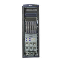
Sun Microsystems Sun Fire E6900 Service Manual (194 pages)
Servers
Brand:
Sun Microsystems
| Category:
Server
| Size: 10 MB
Table of Contents
Service Manual
1
Table of Contents
3
Filler Boards
13
Preface
15
Who Should Use this Document
15
How this Document Is Organized
16
Typographic Conventions
17
Related Documentation
17
Contacting Sun Technical Support
18
Sun Welcomes Your Comments
18
Notes and Cautions
19
1 Safety and Tools Requirements
21
Safety Precautions
21
TABLE 1-1 Safety Precautions
21
Symbols
22
System Precautions
22
TABLE 1-2 Symbols
22
Captive Screws
23
Fan Speed Message
23
Sun Fire Cabinet Fan Tray Power Switches
23
Firmware on Replacement Boards and Assemblies
24
Switzerland Caution
24
Filler Boards and Filler Panels
25
Periodic Maintenance
25
Tools Required
26
2 Powering off and on
27
Powering off the System
27
FIGURE 2-1 Sun Fire System Cabinet Showing Framemanager-Top View
27
FIGURE 2-2 AC Input Boxes-Sun Fire E6900 System-Rear View
28
FIGURE 2-3 AC Input Box-Sun Fire E4900 System-Rear View
28
Powering on the System
29
FIGURE 2-5 Sun Fire Cabinet RTU Circuit Breakers and RTS Power Switch
30
FIGURE 2-6 Cabinet Fan Tray Power Switch-Sun Fire E6900 System Rear View
31
3 Framemanager
33
Framemanager Description
33
FIGURE 3-1 Framemanager
33
Framemanager Leds
34
Replacing the Framemanager
34
TABLE 3-1 Framemanager LED Major Functions
34
FIGURE 3-2 Framemanager Removal-Step
35
FIGURE 3-3 Framemanager Removal-Step
35
FIGURE 3-4 Framemanager Cable Location
36
4 Power
37
Power Supplies
37
Power Supply Slot Locations
38
TABLE 4-1 Specifications for the Power Supplies
38
TABLE 4-2 Power Supply Slot Locations
38
FIGURE 4-1 Power Supply Locations-Sun Fire E6900 System-Front View
39
FIGURE 4-2 Power Supplies in Power Grid 0 and Power Grid 1-Sun Fire E6900 System
40
Power Supply Leds
41
Replacing a Sun Fire E6900 System Power Supply
42
FIGURE 4-4 Removing or Replacing a Power Supply-Sun Fire E6900 System
42
Replacing a Sun Fire E4900 System Power Supply
43
FIGURE 4-5 Removing or Replacing a Power Supply-Sun Fire E4900 System
44
AC Input Box
45
FIGURE 4-6 AC Input Box-Sun Fire E6900 System
45
FIGURE 4-7 AC Input Box-Sun Fire E4900 System
46
FIGURE 4-8 AC Input Boxes-Sun Fire E6900 System-Rear View
47
Replacing the AC Input Box
47
FIGURE 4-10 Removing the AC Input Box-Sun Fire E6900 System
48
FIGURE 4-9 Two Captive Screws on the AC Input Box-Sun Fire E6900 System
48
Redundant Transfer Unit (RTU) and Redundant Transfer Switch (RTS)
49
FIGURE 4-11 RTU and RTS Modules
50
TABLE 4-4 RTS LED Functions
50
FIGURE 4-12 RTS Modules-Sun Fire E6900 System
51
TABLE 4-5 Self-Test LED Functions
51
FIGURE 4-13 RTU Assembly
52
Replacing the RTS Modules
52
Replacing the RTU Assembly
53
5 Patch Panel
55
FIGURE 5-1 Patch Panel Location-Rear View
55
Replacing the Patch Panel
56
6 Fan Trays
57
Fan Tray Slot Numbering
58
FIGURE 6-1 Front and Rear Fan Trays-Sun Fire E6900 System
58
TABLE 6-1 Fan Trays and Their Slot Numbers
58
Fan Tray Leds
59
Replacing Fan Trays in Sun Fire E6900/E4900 Systems
60
Removing a Fan Tray
60
Installing a Fan Tray
61
FIGURE 6-3 Removing or Replacing a Front Fan Tray-Sun Fire E6900 System
61
Cabinet Fan Trays
62
Sun Fire Cabinet Fan Tray Power Switches
62
Replacing the Cabinet Fan Trays
62
FIGURE 6-4 Cabinet Fan Trays
62
FIGURE 6-5 Cabinet Fan Tray Power Switch and Connectors
63
FIGURE 6-6 Cabinet Fan Tray Top Plate
64
7 System Controller Board
65
Handling Boards and Assemblies
65
System Controller Board
66
System Controller Board Slot Locations
67
FIGURE 7-2 System Controller Board Slot Assignments for the Sun Fire E6900 System-Front View
68
System Controller Board Leds
69
Resetting the System Controller Board
70
Replacing a System Controller Board
71
FIGURE 7-4 Reset Switch on a System Controller Board
71
FIGURE 7-5 Loosening the Captive Screws and Ejector Levers
72
FIGURE 7-6 Removing and Replacing a System Controller Board-Sun Fire E6900 System
73
FIGURE 7-7 Tightening the Captive Screws and Locking the Ejector Levers
74
8 Cpu/Memory Boards and Components
77
Handling Boards and Assemblies
77
Filler Panels and Filler Boards
79
Cpu/Memory Boards
79
TABLE 8-1 Cpu/Memory Board LED Functions
79
FIGURE 8-1 Cpu/Memory Board with the Cover Installed
80
FIGURE 8-2 Cpu/Memory Board Slot Assignments-Sun Fire E6900 System-Front View
81
TABLE 8-2 Cpu/Memory Board Slot Locations
81
FIGURE 8-3 Cpu/Memory Board Slot Assignments-Sun Fire E4900 System-Rear View
82
Replacing Cpu/Memory Boards
82
FIGURE 8-4 Unlocking the Ejector Levers
84
FIGURE 8-5 Removing or Replacing a Cpu/Memory Board-Sun Fire E6900 System
85
Replacing Dimms
87
FIGURE 8-6 DIMM Slot Numbers
88
Removing Dimms
89
FIGURE 8-7 Removing a DIMM
90
Installing Dimms
90
FIGURE 8-8 Installing a DIMM
91
Cpu/Memory Board EMI Springfingers Clip
92
Replacing the EMI Springfingers Clip for E6900/E4900 Systems
92
FIGURE 8-9 Removing a Cpu/Memory Board EMI Springfingers Clip
93
FIGURE 8-10 Installing a Cpu/Memory Board EMI Springfingers Clip
95
9 PCI/PCI+/PCI-X I/O Assemblies and Components
97
Handling Boards and Assemblies
97
Filler Boards and Filler Panels
99
PCI/PCI+/PCI-X I/O Assemblies
100
FIGURE 9-3 I/O Assembly
100
FIGURE 9-1 I/O Assemblies for the Sun Fire E6900 System-Rear View
101
FIGURE 9-2 I/O Assemblies for the Sun Fire E4900 System-Rear View
102
I/O Assembly Leds
102
TABLE 9-4 I/O Assembly Status LED Functions
102
Replacing PCI/PCI+/PCI-X I/O Assemblies
103
Replacing PCI Cards
106
FIGURE 9-4 Removing a PCI Card from the I/O Assembly
107
Installing a Pci Card
107
10 Repeater Board
109
Handling Boards and Assemblies
109
Replacing Repeater Boards
109
Filler Boards
110
Repeater Board
110
FIGURE 10-2 Repeater Board Slot Assignments for the Sun Fire E4900 System-Rear View
112
TABLE 10-2 Repeater Board LED Functions
112
FIGURE 10-3 Repeater Board Leds
113
Replacing Repeater Boards
114
FIGURE 10-4 Unlocking the Ejector Levers
115
FIGURE 10-5 Removing and Replacing a Repeater Board-Sun Fire E4900 System
116
11 Centerplane and ID Boards
119
Replacing the Centerplanes in a Sun Fire E6900 System
119
Removing the System Centerplane
119
FIGURE 11-1 Removing the Door-Sun Fire E6900 System
120
FIGURE 11-2 Removing All Components from the Front of the Sun Fire E6900 System
121
FIGURE 11-3 Removing the Bus Bar Access Panels
121
FIGURE 11-4 Loosening the Bus Bar Captive Screws-Sun Fire E6900 System
122
FIGURE 11-5 Disconnecting the Two Cables from the System Centerplane-Sun Fire E6900 System
123
FIGURE 11-6 Removing the Screws Securing the System Centerplane-Sun Fire E6900 System
123
FIGURE 11-7 Moving the System Centerplane Forward off the Guide Pins-Sun Fire E6900 System
124
FIGURE 11-8 Removing the System Centerplane-Sun Fire E6900 System
124
Removing the Fan Centerplane
125
FIGURE 11-9 Disconnecting the Fan Tray Centerplane Cables
125
Removing the Power Centerplane
126
FIGURE 11-10 Removing the Screws Securing the Fan Centerplane
126
FIGURE 11-11 Centerplane Cables-Sun Fire E6900 System
127
FIGURE 11-12 Disconnecting the Screws Securing the Power Centerplane Bus Bars
128
Installing the System Centerplane
129
Installing the Fan Centerplane
129
Replacing the Power Centerplane
130
Replacing the Centerplane in a Sun Fire E4900 System
131
Removing the Centerplane
131
FIGURE 11-13 Removing the Bottom Fan Tray, Cpu/Memory Boards, and I/O Assemblies-Sun Fire E4900 System
132
FIGURE 11-14 Removing the Front Door-Sun Fire E4900 System
133
FIGURE 11-15 Removing a Power Supply at the Front of the Sun Fire E4900 System
134
FIGURE 11-16 Disconnecting Cables from the Connectors on the Centerplane-Sun Fire E4900 System
135
FIGURE 11-17 Removing the Top and Bottom Power Supply Supports-Sun Fire E4900 System
136
FIGURE 11-18 Removing the Cable Guide-Sun Fire E4900 System
137
FIGURE 11-19 Removing the Screws Securing the Centerplane to the System-Sun Fire E4900 System
138
Installing the Centerplane
139
FIGURE 11-20 Removing the Centerplane and Insulator-Sun Fire E4900 System
139
Replacing the ID Boards
141
Removing the ID Board from the Sun Fire E6900 System
141
FIGURE 11-21 Removing IB9 I/O Assembly-Sun Fire E6900 System
142
Installing the ID Board in the Sun Fire E6900 System
143
FIGURE 11-22 Removing the ID Board from the Centerplane-Sun Fire E6900 System
143
Removing the ID Board from the Sun Fire E4900 System
144
Installing the ID Board in the Sun Fire E4900 System
144
12 Periodic Maintenance
147
Cleaning the Air Intake Screen
148
Air Intake Screen for the Sun Fire E6900 System
148
FIGURE 12-1 Air Intake Screen Location for the Sun Fire E6900-Front View
148
Replacing the Sun Fire E6900 Air Intake Screen
149
Air Intake Screen for the Sun Fire E4900 System
150
FIGURE 12-2 Air Intake Screen Location for the Sun Fire E4900-Front View
150
Replacing the Sun Fire E4900 Air Intake Screen
151
Functional Description
153
TABLE A-1 Sun Fire E6900 System Components
154
FIGURE A-1 Sun Fire E6900 System-Front and Rear Views
155
FIGURE A-2 Sun Fire E4900 System-Front and Rear Views
156
FIGURE A-4 Cpu/Memory Board with the Cover Removed
160
TABLE A-4 Cpu/Memory Board Slot Locations
160
TABLE A-5 I/O Assembly Slot Locations
161
FIGURE A-5 PCI/PCI+/PCI-X I/O Assembly
162
FIGURE A-7 Power Supply for the Sun Fire E6900 Systems
164
FIGURE A-9 System Controller Board-E6900/E4900 Systems
166
System Serial Number Locations and Rules for System Configuration
167
FIGURE B-1 Serial Number Location for the Sun Fire E6900 System-Rear
168
FIGURE B-2 Serial Number Location for the Sun Fire E4900 System-Rear
169
FIGURE B-3 Sun Fire Cabinet System Serial Number Location-Rear
170
Illustrated Parts Breakdown
177
FIGURE C-1 Sun Fire E6900 System-Front and Rear Views
178
TABLE C-1 Sun Fire E6900 System Components
179
FIGURE C-2 Sun Fire E6900 System Cabinet
180
FIGURE C-3 Sun Fire E4900 System-Rear View
181
TABLE C-2 Sun Fire E4900 System-Rear View
181
FIGURE C-4 Sun Fire E4900 System-Front View
183
TABLE C-3 Sun Fire E4900 System-Front View
183
FIGURE C-5 Cpu/Memory Board
184
TABLE C-4 Types of Dimms
184
FIGURE C-6 PCI/PCI+/PCI-X I/O Assembly
185
FIGURE C-7 Repeater Board
186
FIGURE C-8 System Controller Board-E6900/E4900 Systems
187
TABLE C-5 Jumpers
187
FIGURE C-9 Power Supply for the Sun Fire E6900 Systems
188
FIGURE C-10 Power Supply for the Sun Fire E4900 System
188
TABLE C-6 Filler Boards and Filler Panels Replacement Parts
189
TABLE C-7 Cable Replacement Parts
190
Advertisement
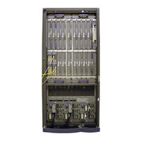
Sun Microsystems Sun Fire E6900 Installation Manual (72 pages)
Brand:
Sun Microsystems
| Category:
Server
| Size: 4 MB
Table of Contents
Table of Contents
3
Preface
29
Preparing for Installation
35
Verifying the Electrical Circuits
35
Verifying the Air Conditioning
36
Verifying the Floor Area
37
Tools
39
Installing the Sun Fire E6900 System
39
FIGURE 2-1 Front Brackets and Front Wheel Stop
40
Moving and Securing the Sun Fire E6900 System
40
FIGURE 2-3 Moving the Sun Fire E6900 System off the Shipping Pallet
42
Adjusting the Leveling Pads
43
Securing the Cabinet to the Floor
43
FIGURE 2-4 Bracketing the Sun Fire E6900 System to the Floor
45
Shipping and Storing the System
45
Connecting Power Cables to the Sun Fire E6900 System
46
FIGURE 2-5 RTS AC Power Switch on the Sun Fire E6900 System
46
FIGURE 2-8 Connecting Power Cables to the RTS Module
48
Connecting the Administrative Console
49
Connecting the I/O Assemblies
49
Section 2.4 "Connecting the I/O Assemblies
49
Section 2.5 "Connecting the Administrative Console
49
Connecting the Administrative Console
50
Connecting the ASCII Terminal
50
FIGURE 2-9 Serial Cable Connections
50
FIGURE 2-10 Primary Ttya Serial Port and Primary Ethernet Connections on the Patch Panel
51
Powering on the Sun Fire E6900 System
52
Section 2.6 "Powering on the Sun Fire E6900 System
52
FIGURE 2-11 Sun Fire E6900 System Power Switch Locations
53
Powering off the Sun Fire E6900 System
54
Section 2.7 "Powering off the Sun Fire E6900 System
54
I/O Card Visibility Issues
55
Installing Additional Hardware
55
Installing Peripheral Devices
55
Section 2.10 "I/O Card Visibility Issues
55
Section 2.8 "Installing Additional Hardware
55
Section 2.9 "Installing Peripheral Devices
55
Installing the Sun Fire E4900 System
57
Mounting the Rails
58
Mounting the Sun Fire E4900 System
58
Section 3.1 "Mounting the Sun Fire E4900 System
58
FIGURE 3-1 Rail Installation in a Sun Fire Cabinet
59
Mounting the Sun Fire E4900 System
59
FIGURE 3-2 Mounting the Sun Fire E4900 System into a Sun Fire Cabinet
61
Connecting Power Cables to the Sun Fire E4900 System
62
Section 3.2 "Connecting Power Cables to the Sun Fire E4900 System
62
FIGURE 3-3 Power Switch Locations on the Cabinet Mounted Sun Fire E4900 System
63
Attaching Cabinet Front Panels
64
Section 3.3 "Attaching Cabinet Front Panels
64
FIGURE 3-4 Cabinet Front Panel Locations
65
Attaching Cabinet Guards
66
FIGURE 3-5 Cabinet Guard Installation
66
Connecting the I/O Assemblies
67
Connecting the System Controller to the Framemanager
67
Section 3.5 "Connecting the System Controller to the Framemanager
67
Section 3.6 "Connecting the I/O Assemblies
67
Connecting the Administrative Console
68
FIGURE 3-6 Primary System Controller Connections on the Sun Fire E4900 System
68
Section 3.7 "Connecting the Administrative Console
68
Connecting the Administrative Console
69
Connecting the ASCII Terminal
69
Installing Additional Hardware
70
Powering off the Sun Fire E4900 System
70
Powering on the Sun Fire E4900 System
70
Section 3.10 "Installing Additional Hardware
70
Section 3.8 "Powering on the Sun Fire E4900 System
70
Section 3.9 "Powering off the Sun Fire E4900 System
70
I/O Card Visibility Issues
71
Installing Peripheral Devices
71
Section 3.11 "Installing Peripheral Devices
71
Section 3.12 "I/O Card Visibility Issues
71
Sun Microsystems Sun Fire E6900 Site Planning Manual (38 pages)
Systems
Brand:
Sun Microsystems
| Category:
Server
| Size: 1 MB
Table of Contents
Table of Contents
3
Preface
9
1 Site Planning Checklist
13
System Components
13
Miscellaneous
13
Environmental Requirements
13
Facility Power Requirements
14
Physical Specifications
14
Planning Your Access Route
14
2 Physical Specifications 2-1
15
System Components
15
FIGURE 2-1 Sun Fire E6900 System
16
FIGURE 2-2 Sun Fire E4900 System Mounted in Optional Sun Fire Cabinet
17
General Physical Guidelines
18
Size and Space Specifications
18
Thermal Clearance Specifications
18
FIGURE 2-6 Sun Fire E6900 and Sun Fire Cabinet-Bottom Views
23
Planning Your Access Route
25
Network Connection Planning
26
Setup and Network Connections
26
Serial Connection
26
Ethernet Connections
26
Platform and Domain Setup Information
27
3 Environmental and Electrical Specifications
29
Environmental Requirements
29
Ambient Temperature Recommendations
30
Ambient Relative Humidity Recommendations
31
Facility Power Requirements
31
Figure
32
FIGURE 3-4 Sun Fire Cabinet for Sun Fire E4900 Configuration: One RTU Assembly and One AC Power Source
33
Electrical and Cooling Specifications
34
Thermal Guidelines for Sun Fire E6900/E4900 Systems
36
Conditions
36
Sun Fire E6900 System Air Flow-Front and Rear
37
Figure
38
Sun Fire E4900 System Air Flow-Front and Rear
38
Advertisement
Sun Microsystems Sun Fire E6900 Installation Manual (7 pages)
High-End and Midrange Systems CPU/Memory Board
Brand:
Sun Microsystems
| Category:
Computer Hardware
| Size: 0 MB
Table of Contents
Locations of the Cpu/Memory Boards
1
Preparing to Install a Cpu/Memory Board
2
Inspecting the New Cpu/Memory Board
2
Installing a Cpu/Memory Board
3
Preparing to Remove a Cpu/Memory Board
4
Removing a Cpu/Memory Board
5
Accessing Sun Documentation
6
Contacting Sun Technical Support
6
Sun Welcomes Your Comments
6
Sun Microsystems Sun Fire E6900 Installation Manual (6 pages)
System Controller Board, Version 2 (Enhanced Memory)
Brand:
Sun Microsystems
| Category:
Controller
| Size: 0 MB
Table of Contents
Location of the System Controller Boards
2
System Controller Board Default Jumper Settings
2
Hot-Plug Installations
3
Installing a System Controller Board
3
Removing a System Controller Board
5
Accessing Sun Documentation
6
Contacting Sun Technical Support
6
Sun Welcomes Your Comments
6
Sun Microsystems Sun Fire E6900 Assembly Installation Manual (4 pages)
Systems PCI I/O
Brand:
Sun Microsystems
| Category:
I/O Systems
| Size: 0 MB
Table of Contents
Location of I/O Assemblies
1
Installing a PCI I/O Assembly
1
Removing a PCI I/O Assembly
3
Accessing Sun Documentation
4
Sun Welcomes Your Comments
4
Sun Microsystems Sun Fire E6900 Assembly Installation Manual (4 pages)
Systems PCI+ I/O
Brand:
Sun Microsystems
| Category:
PCI Card
| Size: 0 MB
Table of Contents
Firmware and os Minimum Requirements
2
Removing a PCI I/O Assembly
2
Installing a PCI+ I/O Assembly
3
Accessing Sun Documentation
4
Advertisement
Related Products
Sun Microsystems Sun Fire E2900
Sun Microsystems Sun Fire E25K
Sun Microsystems Sun Fire E20K
Sun Enterprise 3 00 Series
Sun Microsystems Sun Fire 880
Sun Microsystems SUN FIRE X4640
Sun Microsystems Sun Fire X4150 Server
Sun Microsystems SUN FIRE X4500
Sun Microsystems Sun Fire X4100 M2
Sun Microsystems Sun Fire X4200 M2
Sun Microsystems Categories
Server
Storage
Desktop
Computer Hardware
Adapter
More Sun Microsystems Manuals
Login
Sign In
OR
Sign in with Facebook
Sign in with Google
Upload manual
Upload from disk
Upload from URL