Sun Microsystems Fire E6900 Systems Service Manual
Servers
Hide thumbs
Also See for Fire E6900 Systems:
- Installation manual (72 pages) ,
- Site planning manual (38 pages) ,
- Assembly installation manual (4 pages)

Related Manuals for Sun Microsystems Fire E6900 Systems


Summary of Contents for Sun Microsystems Fire E6900 Systems
-
Page 1: Service Manual
Sun Fire E6900/E4900 Systems ™ Service Manual Sun Microsystems, Inc. www.sun.com Part No. 817-4120-13(v2) May 2006, Revision A Submit comments about this document at: http://www.sun.com/hwdocs/feedback... - Page 2 Products bearing SPARC trademarks are based upon an architecture developed by Sun Microsystems, Inc. The OPEN LOOK and Sun™ Graphical User Interface was developed by Sun Microsystems, Inc. for its users and licensees. Sun acknowledges the pioneering efforts of Xerox in researching and developing the concept of visual or graphical user interfaces for the computer industry. Sun holds a non-exclusive license from Xerox to the Xerox Graphical User Interface, which license also covers Sun’s licensees who implement OPEN...
-
Page 3: Table Of Contents
Contents Preface xv Safety and Tools Requirements 1–1 Safety Precautions 1–1 Symbols 1–2 System Precautions 1–2 1.3.1 Captive Screws 1–3 1.3.2 Fan Speed Message 1–3 1.3.3 Sun Fire Cabinet Fan Tray Power Switches 1–3 1.3.4 Firmware On Replacement Boards and Assemblies 1–4 1.3.5 Switzerland Caution 1–4 Filler Boards and Filler Panels 1–5... - Page 4 FrameManager LEDs 3–2 Replacing the FrameManager 3–2 Power 4–1 Power Supplies 4–1 4.1.1 Power Supply Slot Locations 4–2 4.1.2 Power Supply LEDs 4–5 4.1.3 Replacing a Sun Fire E6900 System Power Supply 4–6 4.1.4 Replacing a Sun Fire E4900 System Power Supply 4–7 AC Input Box 4–9 4.2.1 Replacing the AC Input Box 4–11...
- Page 5 Handling Boards and Assemblies 7–1 System Controller Board 7–2 7.2.1 System Controller Board Slot Locations 7–3 7.2.2 System Controller Board LEDs 7–5 7.2.3 Resetting the System Controller Board 7–6 7.2.4 Replacing a System Controller Board 7–7 CPU/Memory Boards and Components 8–1 Handling Boards and Assemblies 8–1 Filler Panels and Filler Boards 8–3 CPU/Memory Boards 8–3...
- Page 6 Centerplane and ID Boards 11–1 11.1 Replacing the Centerplanes in a Sun Fire E6900 System 11–1 11.1.1 Removing the System Centerplane 11–1 11.1.2 Removing the Fan Centerplane 11–7 11.1.3 Removing the Power Centerplane 11–8 11.1.4 Installing the System Centerplane 11–11 11.1.5 Installing the Fan Centerplane 11–11 11.1.6...
- Page 7 Index Index–1 Contents...
- Page 8 viii Sun Fire E6900/E4900 Systems Service Manual • May 2006...
- Page 9 Figures Sun Fire System Cabinet Showing FrameManager—Top View 2–1 FIGURE 2-1 AC Input Boxes—Sun Fire E6900 System—Rear View 2–2 FIGURE 2-2 AC Input Box—Sun Fire E4900 System—Rear View 2–2 FIGURE 2-3 Redundant Transfer Switches (RTS)—Sun Fire E6900 System 2–3 FIGURE 2-4 Sun Fire Cabinet RTU Circuit Breakers and RTS Power Switch 2–4 FIGURE 2-5 Cabinet Fan Tray Power Switch—Sun Fire E6900 System Rear View 2–5...
- Page 10 RTU and RTS Modules 4–14 FIGURE 4-11 RTS Modules—Sun Fire E6900 System 4–15 FIGURE 4-12 RTU Assembly 4–16 FIGURE 4-13 Patch Panel Location—Rear View 5–1 FIGURE 5-1 Front and Rear Fan Trays—Sun Fire E6900 System 6–2 FIGURE 6-1 Rear and Front Fan Trays—Sun Fire E4900 System 6–3 FIGURE 6-2 Removing or Replacing a Front Fan Tray—Sun Fire E6900 System 6–5 FIGURE 6-3...
- Page 11 Removing a PCI Card From the I/O Assembly 9–11 FIGURE 9-4 Repeater Board Slot Assignments for the Sun Fire E6900 System—Rear View 10–3 FIGURE 10-1 Repeater Board Slot Assignments for the Sun Fire E4900 System—Rear View 10–4 FIGURE 10-2 Repeater Board LEDs 10–5 FIGURE 10-3 Unlocking the Ejector Levers 10–7 FIGURE 10-4...
- Page 12 FIGURE A-4 PCI/PCI+/PCI-X I/O Assembly A–10 FIGURE A-5 PCI Card A–11 FIGURE A-6 Power Supply for the Sun Fire E6900 Systems A–12 FIGURE A-7 Power Supply for the Sun Fire E4900 System A–13 FIGURE A-8 System Controller Board—E6900/E4900 Systems A–14 FIGURE A-9 Serial Number Location for the Sun Fire E6900 System—Rear B–2...
-
Page 13: Filler Boards
Tables Safety Precautions 1–1 TABLE 1-1 Symbols 1–2 TABLE 1-2 Overheating Precautions Using Filler Boards 1–5 TABLE 1-3 FrameManager LED Major Functions 3–2 TABLE 3-1 Specifications for the Power Supplies 4–2 TABLE 4-1 Power Supply Slot Locations 4–2 TABLE 4-2 Power Supply LED Functions 4–5 TABLE 4-3 RTS LED Functions 4–14... - Page 14 Repeater Board LED Functions 10–4 TABLE 10-2 Sun Fire E6900 System Components A–2 TABLE A-1 FrameManager LCD Displays A–5 TABLE A-2 FrameManager LED Functions A–6 TABLE A-3 CPU/Memory Board Slot Locations A–8 TABLE A-4 I/O Assembly Slot Locations A–9 TABLE A-5 PCI I/O Assemblies A–11 TABLE A-6 PCI+/PCI-X I/O Assemblies A–11...
-
Page 15: Preface
Preface This document describes how to remove and install field-replaceable units (FRUs). This document also presents a functional description of the systems, configuration rules, and illustrated parts breakdowns for each system. Who Should Use This Document Caution – This document is written for qualified service-trained maintenance providers. -
Page 16: How This Document Is Organized
How This Document Is Organized This document contains the following chapters and appendixes: Chapter 1 describes the safety precautions and tools you will need. Chapter 2 describes how to power on and power off the system. Chapter 3 describes how to install and remove the FrameManager. Chapter 4 describes how to install and remove the power supplies, the AC input box, the redundant transfer unit (RTU), and the redundant transfer switches (RTS). -
Page 17: Typographic Conventions
Typographic Conventions Typographic Conventions TABLE P-1 Typeface Meaning Examples AaBbCc123 Document titles, new words or Read Chapter 6 in the User’s Guide. terms, words to be emphasized These are called class options. You must be superuser to do this. Related Documentation The documents listed as online are available at: http://www.sun.com/products-n-solutions/hardware/docs/ Application... -
Page 18: Contacting Sun Technical Support
Documentation, Support, and Training Sun Function Documentation http://www.sun.com/documentation/ Support http://www.sun.com/support/ Training http://www.sun.com/training/ Contacting Sun Technical Support If you have technical questions about this product which are not answered in this document, go to: http://www.sun.com/service/contacting Sun Welcomes Your Comments Sun is interested in improving its documentation and welcomes your comments and suggestions. -
Page 19: Notes And Cautions
Notes and Cautions Note – Procedures contained in this document must be performed by qualified service-trained maintenance providers. Before you begin, carefully read each of the procedures in this manual. If you have not performed similar operations on comparable equipment, do not attempt to perform these procedures. Caution –... - Page 20 xx Sun Fire E6900/E4900 Systems Service Manual • May 2006...
-
Page 21: Safety And Tools Requirements
C H A P T E R Safety and Tools Requirements This chapter describes the safety and system precautions you must take when servicing the system. It also lists the tools and equipment you will need. Safety Precautions For your protection, observe the following safety precautions when servicing your equipment: Follow all cautions, warnings, and instructions marked on the equipment. -
Page 22: Symbols
Symbols Symbols TABLE 1-2 Symbol Description Meaning CAUTION Hazardous voltages are present. To reduce the risk of electrical shock and danger, follow the instructions. CAUTION Risk of personal injury or equipment damage. To reduce the risk, follow the instructions. CAUTION CAUTION: Hot surfaces. -
Page 23: Captive Screws
Caution – DO NOT make mechanical or electrical modifications to the system or the cabinet. Sun Microsystems is not responsible for regulatory compliance of modified cabinets. Caution – The chassis AC power cord(s) must remain connected to ensure a proper ground. -
Page 24: Firmware On Replacement Boards And Assemblies
1.3.4 Firmware On Replacement Boards and Assemblies After installing a board or assembly, use the showboards -p proms command to determine if the firmware needs to be updated. If an update is required, use either the system controller flashupdate -f or flashupdate -c command. Refer to the Sun Fire 6800/4810/4800/3800 System Controller Command Reference Manual for correct usage of the flashupdate command. -
Page 25: Filler Boards And Filler Panels
Filler Boards and Filler Panels Filler boards and filler panels are used for EMI protection and to ensure proper air flow in order to prevent the system from overheating. describes the precautions you must take when you remove boards or TABLE 1-3 assemblies from a system. -
Page 26: Tools Required
If the air intake screen collects a substantial amount of debris in less than three months, investigate the air supply system for sources of contamination and take corrective action. In addition, notify and update account management, as required. Have spare air intake screens onsite so that replacements are available when needed for cleaning. -
Page 27: Powering Off And On
C H A P T E R Powering Off and On This chapter describes how to power the system off and on. These systems do not have a physical keyswitch. Before physically powering off the system, you must halt the Solaris operating environment in each domain and then power off the domain. Powering Off the System 1. -
Page 28: Figure 2-2 Ac Input Boxes-Sun Fire E6900 System-Rear View
3. Turn off the AC input box(es) ( FIGURE 2-2 FIGURE 2-3 AC input box AC input box AC Input Boxes—Sun Fire E6900 System—Rear View FIGURE 2-2 AC input box AC Input Box—Sun Fire E4900 System—Rear View FIGURE 2-3 Sun Fire E6900/E4900 Systems Service Manual • May 2006... -
Page 29: Powering On The System
4. For Sun Fire E6900 system or Sun Fire E4900 system mounted in a Sun Fire cabinet, turn off the redundant transfer switches (RTS) ( FIGURE 2-4 System rear System front Redundant Transfer Switches (RTS)—Sun Fire E6900 System FIGURE 2-4 Powering On the System 1. -
Page 30: Figure 2-5 Sun Fire Cabinet Rtu Circuit Breakers And Rts Power Switch
2. Check that all of the circuit breakers on each side of the RTU are on. Circuit breakers RTS0 module power switch Sun Fire Cabinet RTU Circuit Breakers and RTS Power Switch FIGURE 2-5 3. Turn on the AC input box(es). on page 2-1 on page 2-2. -
Page 31: Figure 2-6 Cabinet Fan Tray Power Switch-Sun Fire E6900 System Rear View
Power switch Cabinet Fan Tray Power Switch—Sun Fire E6900 System Rear View FIGURE 2-6 Chapter 2 Powering Off and On... - Page 32 Sun Fire E6900/E4900 Systems Service Manual • May 2006...
-
Page 33: Framemanager
C H A P T E R FrameManager This chapter provides procedures for field-replaceable FrameManager units within a Sun Fire E6900 system cabinet. The following sections are included in this chapter: Section 3.1, “FrameManager Description” on page 3-1 ■ Section 3.2, “FrameManager LEDs” on page 3-2 ■... -
Page 34: Framemanager Leds
FrameManager LEDs The LEDs indicate the status of the individual device. The FrameManager has three LEDs: power, fault, and service ( TABLE 3-1 FrameManager LED Major Functions TABLE 3-1 Function Operation Green LED Power On when the RTS has been commanded to enable switched power. -
Page 35: Figure 3-2 Framemanager Removal-Step
FrameManager Removal—Step 1 FIGURE 3-2 2. Slide the assembly forward and carefully flip it onto the top of the cabinet to access the cable connector on the rear of the assembly ( FIGURE 3-3 FrameManager Removal—Step 2 FIGURE 3-3 3. Disconnect the five cables from the assembly ( FIGURE 3-4 Chapter 3 FrameManager... -
Page 36: Figure 3-4 Framemanager Cable Location
FrameManager Cable Location FIGURE 3-4 4. Remove the assembly from the top of the cabinet. Caution – Make sure that the keyswitch of the replacement FrameManager is in the same position as the keyswitch of the removed FrameManager. Not doing so could cause the system to be inadvertently powered off when the replacement FrameManager is reconnected to the five cables. -
Page 37: Power
C H A P T E R Power This chapter describes how to remove and replace power supplies and the AC input box. Location information on the RTS modules is also provided. To protect both yourself and the equipment, make sure you follow the safety precautions in Chapter 1 “Safety and Tools Requirements.”... -
Page 38: Power Supply Slot Locations
lists the specifications for the power supplies. TABLE 4-1 Specifications for the Power Supplies TABLE 4-1 Power Supplies Main Voltage Auxiliary Voltage System Type per System Output DC Output DC Sun Fire E6900 Sun Fire E4900 There are four alternating current (AC) power cords for the Sun Fire E6900 system. There are three AC power cords for the Sun Fire E4900 systems. -
Page 39: Figure 4-1 Power Supply Locations-Sun Fire E6900 System-Front View
Power Supply Locations—Sun Fire E6900 System—Front View FIGURE 4-1 Chapter 4 Power... -
Page 40: Figure 4-2 Power Supplies In Power Grid 0 And Power Grid 1-Sun Fire E6900 System
illustrates the power supplies in power grid 0 and power FIGURE 4-2 grid 1. Power supplies in power grid 1 Power supplies in power grid 0 Power Supplies in Power Grid 0 and Power Grid 1—Sun Fire E6900 System FIGURE 4-2 Sun Fire E6900/E4900 Systems Service Manual •... -
Page 41: Power Supply Leds
In the Sun Fire E4900, install the power supplies in this order: PS0, PS1, and PS2. Power Supply Locations—Sun Fire E4900 System—Front View FIGURE 4-3 4.1.2 Power Supply LEDs There are three LEDs on each power supply. notes the LED functions. TABLE 4-3 Power Supply LED Functions TABLE 4-3... -
Page 42: Replacing A Sun Fire E6900 System Power Supply
4.1.3 Replacing a Sun Fire E6900 System Power Supply 4.1.3.1 Removing a Sun Fire E6900 System Power Supply 1. Power off the appropriate power supply. Refer to the Sun Fire Midrange Systems Platform Administration Manual for complete procedures for powering off the power supply. Note –... -
Page 43: Replacing A Sun Fire E4900 System Power Supply
4.1.3.2 Installing a Sun Fire E6900 System Power Supply 1. Remove the power supply filler panel if present. 2. Slide the power supply into the slot ( FIGURE 4-4 3. Lock the ejector by pushing the ejector up. 4. Tighten the two captive screws. Note –... -
Page 44: Figure 4-5 Removing Or Replacing A Power Supply-Sun Fire E4900 System
Ejectors Captive screw Removing or Replacing a Power Supply—Sun Fire E4900 System FIGURE 4-5 4. Unlock the ejectors by pushing the ejectors outward. 5. Slide the power supply out. 6. If no replacement, install a power supply filler panel to cover the empty slot. 4.1.4.2 Installing a Sun Fire E4900 System Power Supply 1. -
Page 45: Ac Input Box
7. Turn on the power supply by using the system controller software. Refer to the Sun Fire Midrange Systems Platform Administration Manual for complete procedures for powering on the power supply. 8. Make sure the green Activated LED is lit. If the green Activated LED is not on, check to see if the power supply is seated properly and the power supply is turned on. -
Page 46: Figure 4-7 Ac Input Box-Sun Fire E4900 System
AC input AC Input Box—Sun Fire E4900 System FIGURE 4-7 4-10 Sun Fire E6900/E4900 Systems Service Manual • May 2006... -
Page 47: Replacing The Ac Input Box
AC input box AC input box AC Input Boxes—Sun Fire E6900 System—Rear View FIGURE 4-8 4.2.1 Replacing the AC Input Box 4.2.1.1 Removing the AC Input Box 1. Power off the system. Refer to the Sun Fire Midrange Systems Platform Administration Manual for complete procedures for powering off the system. -
Page 48: Figure 4-9 Two Captive Screws On The Ac Input Box-Sun Fire E6900 System
Captive screws Two Captive Screws on the AC Input Box—Sun Fire E6900 System FIGURE 4-9 5. Slide the AC input box out of the chassis ( FIGURE 4-10 Removing the AC Input Box—Sun Fire E6900 System FIGURE 4-10 4.2.1.2 Installing the AC Input Box 1. -
Page 49: Redundant Transfer Unit (Rtu) And Redundant Transfer Switch (Rts)
4. Power on the system. Refer to the Sun Fire Midrange Systems Platform Administration Manual for complete procedures for powering on the system. Redundant Transfer Unit (RTU) and Redundant Transfer Switch (RTS) The Sun Fire E6900 system has two RTUs. Each RTU contains two RTS modules. The primary configuration is the left RTS module with the right RTS module as secondary for redundancy. -
Page 50: Figure 4-11 Rtu And Rts Modules
Unswitched outlet (powered) LEDs Unswitched outlet (unpowered) Circuit breaker Switched Switched outlets outlets RTS0 module RTU and RTS Modules FIGURE 4-11 describes the RTS LED functions. TABLE 4-4 RTS LED Functions TABLE 4-4 LED Position Color Status Meaning Left Green The source is present and is within specifications. -
Page 51: Figure 4-12 Rts Modules-Sun Fire E6900 System
During a self-test when you power on the system, the LEDs function as described in TABLE 4-5 Self-Test LED Functions TABLE 4-5 LEDs Flashing Pattern Meaning Three times Self-test is complete Right, middle, left LED test is complete Middle Flashing for three seconds Seating test in progress Shows the location and numbering of the RTS modules. -
Page 52: Replacing The Rts Modules
4.3.1 Replacing the RTS Modules 1. For systems with redundant RTS modules, skip to Step 3. 2. For systems with non-redundant RTS modules, power off the system. Refer to the Sun Fire Midrange Systems Platform Administration Manual for complete procedures for powering off the system. 3. -
Page 53: Replacing The Rtu Assembly
4.3.2 Replacing the RTU Assembly 1. Notify users that the system will be powered off. 2. Power off the system. 3. Power off the wall circuit breaker connected to the RTS module(s) that are to be removed. 4. Label and remove all cabling. 5. - Page 54 4-18 Sun Fire E6900/E4900 Systems Service Manual • May 2006...
-
Page 55: Patch Panel
C H A P T E R Patch Panel This chapter provides procedures for the field-replaceable patch panel within the Sun Fire E6900 system cabinet. The following sections are included in this chapter: Section 5.1, “Patch Panel” on page 5-1 ■... -
Page 56: Replacing The Patch Panel
Replacing the Patch Panel 1. Label and remove all cabling. 2. Loosen the four captive screws. 3. Remove the Patch Panel unit. 4. Install the replacement unit by reversing Step 1 through Step 3. Sun Fire E6900/E4900 Systems Service Manual • May 2006... -
Page 57: Fan Trays
C H A P T E R Fan Trays This chapter describes how to remove and replace fan trays. To protect both yourself and the equipment, make sure you follow the safety precautions in Chapter This chapter contains the following sections: Section 6.1, “Fan Tray Slot Numbering”... -
Page 58: Fan Tray Slot Numbering
Fan Tray Slot Numbering lists the fan trays, their slot numbers, and identifies the redundant fan tray TABLE 6-1 for each system. Fan Trays and Their Slot Numbers TABLE 6-1 System Fan Tray Location Sun Fire E6900 system Rear Front Rear Front (redundant) Sun Fire E4900 system... -
Page 59: Fan Tray Leds
Rear and Front Fan Trays—Sun Fire E4900 System FIGURE 6-2 Fan Tray LEDs There are three LEDs on each fan tray describes the LED functions. TABLE 6-2 Fan Tray LED Functions TABLE 6-2 Activated LED (green) Device is activated; you cannot Device is deactivated;... -
Page 60: Replacing Fan Trays In Sun Fire E6900/E4900 Systems
Replacing Fan Trays in Sun Fire E6900/E4900 Systems 6.3.1 Removing a Fan Tray Caution – Within one minute of removing the fan tray, install a filler panel to prevent the system from overheating. 1. Make sure you have a replacement fan tray or filler panel available. 2. -
Page 61: Installing A Fan Tray
Captive screw Captive screw Removing or Replacing a Front Fan Tray—Sun Fire E6900 System FIGURE 6-3 6.3.2 Installing a Fan Tray Caution – Within one minute of removing the filler panel, install a fan tray to prevent the system from overheating. 1. -
Page 62: Cabinet Fan Trays
Cabinet Fan Trays Two fan trays provide additional cooling for the Sun Fire E6900 system. Both are located on the cabinet top immediately behind the FrameManager ( FIGURE 6-4 Cabinet fan trays Cabinet Fan Trays FIGURE 6-4 6.4.1 Sun Fire Cabinet Fan Tray Power Switches If the Sun Fire cabinet fan trays are not operating, make sure that the fan trays are switched on. -
Page 63: Figure 6-5 Cabinet Fan Tray Power Switch And Connectors
Rear view Fan trays (2) Connectors (2) Cabinet Fan Tray Power Switch and Connectors FIGURE 6-5 2. Open the rear door for easier access. 3. Disconnect and then remove the two connectors from the rear of the fan tray FIGURE 6-5 4. -
Page 64: Figure 6-6 Cabinet Fan Tray Top Plate
Screws (2) Top plate Cabinet Fan Tray Top Plate FIGURE 6-6 5. Remove the fan assembly top plate. This will reveal two captive screws. 6. Loosen the two captive screws. 7. Remove the fan tray assembly by supporting the fan tray with one hand while raising the end containing the connectors and then pulling slightly forward. -
Page 65: System Controller Board
C H A P T E R System Controller Board This chapter describes how to remove and replace the system controller board. To protect both yourself and the equipment, make sure you follow the precautions in Chapter 1 “Safety and Tools Requirements.”... -
Page 66: System Controller Board
Caution – The system is sensitive to static electricity. To prevent damage to the board, connect an antistatic wrist strap or foot strap between you and the system. Caution – The System Controller board and its modules have surface-mount components that can be broken if you flex the board. To minimize the amount of board flexing, observe the following precautions: Hold the board by the edges and by the rear panel, which is attached to the ■... -
Page 67: System Controller Board Slot Locations
For the connector, captive screw, ejector lever, and reset switch locations, see FIGURE 7-1 Ethernet port Serial port OK to remove LED (amber) Fault LED (amber) Reset switch Captive Activated Ejector lever screw LED (green) System Controller Board for Sun Fire E6900/E4900 Systems FIGURE 7-1 7.2.1 System Controller Board Slot Locations... -
Page 68: Figure 7-2 System Controller Board Slot Assignments For The Sun Fire E6900 System-Front View
SSC1 SSC0 System Controller Board Slot Assignments for the Sun Fire E6900 FIGURE 7-2 System—Front View Sun Fire E6900/E4900 Systems Service Manual • May 2006... -
Page 69: System Controller Board Leds
SSC1 SSC0 System Controller Board Slot Assignments for the Sun Fire E4900 FIGURE 7-3 System—Rear View 7.2.2 System Controller Board LEDs There are three LEDs on the System Controller board. notes the LED TABLE 7-2 functions. System Controller Board LED Functions TABLE 7-2 LED Name and Location Activated LED (green) -
Page 70: Resetting The System Controller Board
7.2.3 Resetting the System Controller Board Caution – For all SC-App versions, resetting a System Controller should be an absolute last resort, it is always preferable to try the reboot command first. If the System Controller can not be rebooted, it is safer to take all the domains down before attempting to reset it. -
Page 71: Replacing A System Controller Board
Reset switch Reset Switch on a System Controller Board FIGURE 7-4 7.2.4 Replacing a System Controller Board 7.2.4.1 Removing the System Controller Board with Firmware 5.16.x or Later Versions. 1. Complete the software procedures for preparing to remove the System Controller board. -
Page 72: Figure 7-5 Loosening The Captive Screws And Ejector Levers
4. Loosen the two captive screws ( ) on the System Controller board by FIGURE 7-5 using a Phillips No. 2 screwdriver. These screws are springloaded. They will pop out when completely unfastened. 5. Pull outward on the board ejectors to unseat the board ( FIGURE 7-5 Ejector lever Captive screw... -
Page 73: Figure 7-6 Removing And Replacing A System Controller Board-Sun Fire E6900 System
6. Slide the board out ( FIGURE 7-6 illustrates how to install or remove the board for a Sun Fire E6900 system. FIGURE 7-6 This is similar also to the Sun Fire E4900 system. Removing and Replacing a System Controller Board—Sun Fire E6900 System FIGURE 7-6 7.2.4.2 Installing the System Controller Board... -
Page 74: Figure 7-7 Tightening The Captive Screws And Locking The Ejector Levers
Caution – Do Not Force any board into a slot; this can cause damage to the board and system. The board should insert and seat smoothly. If it binds, remove the board and inspect the card cage slot for any obvious obstructions. 4. - Page 75 7. Complete the software procedures for installing the System Controller board. Refer to the Sun Fire Midrange Systems Platform Administration Manual, Chapter “Removing and Replacing Boards.” Chapter 7 System Controller Board 7-11...
- Page 76 7-12 Sun Fire E6900/E4900 Systems Service Manual • May 2006...
-
Page 77: Cpu/Memory Boards And Components
C H A P T E R CPU/Memory Boards and Components To protect both yourself and the equipment, make sure you follow the precautions in Chapter This chapter contains the following sections: Section 8.1, “Handling Boards and Assemblies” on page 8-1 ■... - Page 78 Caution – The system is sensitive to static electricity. To prevent damage to the board, connect an antistatic wrist strap between you and the system. Caution – The CPU/Memory boards have surface-mount components that can be broken if you flex the boards. To minimize the amount of board flexing, observe the following precautions: Hold the board only by the handle and by the edges near the middle of the board, ■...
-
Page 79: Filler Panels And Filler Boards
Filler Panels and Filler Boards In order to prevent the system from overheating, see Section 1.4, “Filler Boards and Filler Panels” on page 1-5 for procedures you must follow when removing CPU/Memory boards from a system. CPU/Memory Boards All systems support the following: Up to four CPU processors with each processor supporting two DIMM (dual ■... -
Page 80: Figure 8-1 Cpu/Memory Board With The Cover Installed
CPU/Memory Board With the Cover Installed FIGURE 8-1 Description CPU processor 1 land area CPU processor 0 land area CPU processor 3 land area CPU processor 2 land area Ejector lever Activated LED (green) Fault LED (amber) OK to remove LED (amber or blue) Ejector lever DIMMs Sun Fire E6900/E4900 Systems Service Manual •... -
Page 81: Figure 8-2 Cpu/Memory Board Slot Assignments-Sun Fire E6900 System-Front View
shows the CPU/Memory board slot locations. TABLE 8-2 CPU/Memory Board Slot Locations TABLE 8-2 System Number of Slots Slot Numbers Location Sun Fire E6900 SB0, SB1, SB2, SB3, SB4, Front Sun Fire E4900 SB0, SB2, SB4 Rear illustrate the slot numbers for the CPU/Memory boards FIGURE 8-2 FIGURE 8-3 for all systems. -
Page 82: Replacing Cpu/Memory Boards
CPU/Memory Board Slot Assignments—Sun Fire E4900 System—Rear View FIGURE 8-3 8.3.1 Replacing CPU/Memory Boards Caution – Remove a board from a powered-on system only after the Solaris operating environment dynamic reconfiguration (DR) software has disabled the board. Refer to the Sun Fire Midrange Systems Dynamic Reconfiguration User Guide for complete procedures. - Page 83 8.3.1.1 Removing the CPU/Memory Board Caution – The CPU/Memory board is heavy and weighs approximately 17 to 22 pounds (7.7 to 9.0 kg). Take care when removing the board from the system. 1. Prepare the system to remove the CPU/Memory board. Two methods can be used to prepare the board: Refer to the Sun Fire Midrange Systems Platform Administration Manualfor complete ■...
-
Page 84: Figure 8-4 Unlocking The Ejector Levers
4. Unlock the ejector levers on the CPU/Memory board with a Phillips No. 2 screwdriver ( FIGURE 8-4 The ejectors will pop out slightly. Unlocking the Ejector Levers FIGURE 8-4 5. Manually rotate the ejector levers until they are 90 degrees straight out from the board ( FIGURE 8-4 This action unseats the board from the connector. -
Page 85: Figure 8-5 Removing Or Replacing A Cpu/Memory Board-Sun Fire E6900 System
Removing or Replacing a CPU/Memory Board—Sun Fire E6900 System FIGURE 8-5 7. Place the board on a grounded ESD mat or the open shipping carton. Caution – To prevent overheating when the system is powered back on, install a filler board or filler panel in the empty slot if no replacement board is going to be installed. - Page 86 a. Inspect the connector on the board being installed. Remove the connector protective cover. Check to see if the plastic is deformed or damaged, including both the pin holes and the fins. Insure there are no major (out of the normal) gaps between each pin row. b.
-
Page 87: Replacing Dimms
4. Simultaneously rotate both ejectors until they are in the closed position (flush with the board). When the board is properly installed, the ejectors will lock automatically. Note – The board will not be recognized until the domain has been dynamically reconfigured to include the board. -
Page 88: Figure 8-6 Dimm Slot Numbers
processor 1/B processor 0/A processor 3/D Bank 0, DIMM 3 Bank 1, DIMM 3 Bank 0, DIMM 2 processor 2/C Bank 1, DIMM 2 Bank 0, DIMM 1 Bank 1, DIMM 1 Bank 0, DIMM 0 Bank 1, DIMM 0 DIMM Slot Numbers FIGURE 8-6 The DIMM numbers and bank numbers are repeated in the same order for all the... -
Page 89: Removing Dimms
8.3.2.1 DIMM Bank Configuration Guidelines Follow these DIMM configuration guidelines: Each DIMM bank must be fully populated with the same capacity DIMM. ■ Install the larger capacity DIMMs into banks before installing the smaller capacity ■ DIMMs into banks. The minimum number of DIMMs you can install per CPU processor is four ■... -
Page 90: Figure 8-7 Removing A Dimm
DIMM Ejection lever Removing a DIMM FIGURE 8-7 5. Holding the DIMM by its edges, remove it from the slot and place it on an antistatic surface. 8.3.2.3 Installing DIMMs Install one bank completely on each board before installing the remaining banks on any board. -
Page 91: Figure 8-8 Installing A Dimm
3. Carefully remove the new DIMM from its protective packaging and place it on an antistatic surface. The bag that the DIMM is packed in makes a good antistatic surface. 4. Press down on the ejector levers at both ends of the DIMM connector slot that will receive the new DIMM. -
Page 92: Cpu/Memory Board Emi Springfingers Clip
CPU/Memory Board EMI Springfingers Clip 8.4.1 Replacing the EMI Springfingers Clip for E6900/E4900 Systems The CPU/Memory EMI springfingers clip can be installed in one orientation only, with the rivets towards the sheet metal flange on the chassis. The clip is symmetrical, the top and bottom orientation is the same. -
Page 93: Figure 8-9 Removing A Cpu/Memory Board Emi Springfingers Clip
Removing a CPU/Memory Board EMI Springfingers Clip FIGURE 8-9 Chapter 8 CPU/Memory Boards and Components 8-17... - Page 94 8.4.1.2 Installing a CPU/Memory Board EMI Springfingers Clip 1. Starting at the top or bottom of the clip, press the plastic rivet into its corresponding hole in the chassis. You can feel the plastic rivet seating into its hole. FIGURE 8-10 2.
-
Page 95: Figure 8-10 Installing A Cpu/Memory Board Emi Springfingers Clip
Installing a CPU/Memory Board EMI Springfingers Clip FIGURE 8-10 Chapter 8 CPU/Memory Boards and Components 8-19... - Page 96 8-20 Sun Fire E6900/E4900 Systems Service Manual • May 2006...
-
Page 97: Pci/Pci+/Pci-X I/O Assemblies And Components
C H A P T E R PCI/PCI+/PCI-X I/O Assemblies and Components The PCI/PCI+/PCI-X I/O assembly is supported in the E6900/E4900 systems. This chapter provides an overview of the I/O assembly, including how to remove and install the I/O assembly and PCI cards. This chapter contains the following sections: Section 9.1, “Handling Boards and Assemblies”... - Page 98 Caution – The system is sensitive to static electricity. To prevent damage to the assembly, connect an antistatic wrist strap between you and the system. Caution – The I/O assemblies, their modules, and cards have surface-mount components that can be broken by flexing the assemblies. To minimize the amount of board flexing, observe the following precautions: Hold the board only by the edges near the middle of the board, where the board ■...
-
Page 99: Filler Boards And Filler Panels
Filler Boards and Filler Panels To prevent the system from overheating, see Section 1.4, “Filler Boards and Filler Panels” on page 1-5 for procedures you must follow when removing the I/O assembly from a powered-on system. Caution – You must install a filler panel that covers only the front of the assembly slot, if the system is to be powered up without the I/O assembly installed. -
Page 100: Pci/Pci+/Pci-X I/O Assemblies
PCI/PCI+/PCI-X I/O Assemblies Description of the PCI I/O Assembly TABLE 9-1 I/O Assembly Description PCI I/O Assembly Eight PCI slots. Six slots for full-length PCI I/O cards, and two short slots for short PCI I/O cards. Short PCI cards can be installed in any of the six full-length slots as well. -
Page 101: Figure 9-1 I/O Assemblies For The Sun Fire E6900 System-Rear View
Location Requirements for the Sun Fire E6900 System illustrates the I/O assembly locations in the Sun Fire E6900 system. FIGURE 9-1 I/O Assemblies for the Sun Fire E6900 System—Rear View FIGURE 9-1 When you install I/O assemblies into the Sun Fire E6900 system, you can install them in either the top or bottom I/O locations. -
Page 102: I/O Assembly Leds
Location Requirements for the Sun Fire E4900 System illustrates the I/O assembly locations in the Sun Fire E4900 system. FIGURE 9-2 I/O Assemblies for the Sun Fire E4900 System—Rear View FIGURE 9-2 9.3.1 I/O Assembly LEDs There are three I/O assembly status LEDs on the PCI/PCI+/PCI-X I/O assembly TABLE 9-4 I/O Assembly Status LED Functions TABLE 9-4... -
Page 103: Replacing Pci/Pci+/Pci-X I/O Assemblies
9.3.2 Replacing PCI/PCI+/PCI-X I/O Assemblies Caution – Remove an assembly from a powered-on system only after the Solaris operating environment dynamic reconfiguration (DR) software has disabled that assembly. Refer to the Sun Fire Midrange Systems Dynamic Reconfiguration User Guide for complete procedures. 9.3.2.1 Removing an I/O Assembly 1. - Page 104 Captive Ejector lever screw I/O Assembly FIGURE 9-3 7. Simultaneously pull the two ejector levers outward to unseat the I/O assembly. This action releases the board from the connectors. Caution – You must install the filler panel within one minute of removing the I/O assembly to prevent overheating.
- Page 105 1. Attach a wrist strap or foot strap. Connect the ESD strap to the system. Place a grounded ESD mat close to the system. Caution – You must install the I/O assembly within one minute of removing the filler panel to prevent overheating. 2.
-
Page 106: Replacing Pci Cards
9.3.3 Replacing PCI Cards To remove and replace PCI cards, you must remove the I/O assembly from the system and place it on an ESD mat. 9.3.3.1 Removing a PCI Card 1. Attach a wrist strap or foot strap. Connect the ESD strap to the system. Place a grounded ESD mat close to the system. -
Page 107: Figure 9-4 Removing A Pci Card From The I/O Assembly
Removing a PCI Card From the I/O Assembly FIGURE 9-4 4. If you are not going to replace the PCI card, insert a filler board into the empty slot. 9.3.3.2 Installing a PCI Card Caution – PCI cards longer than 6.6 inches (167 mm) must be installed in a long slot. - Page 108 3. Line up the screw hole on the mounting bracket with the mounting hole. 4. Slide the card down vertically between the two embossed fixtures on the front of the PCI panel. Look for bumps between the slots on the rear panel. Slide the card in between the bumps.
-
Page 109: Repeater Board
C H A P T E R Repeater Board To protect both yourself and the equipment, make sure you follow the precautions in Chapter 1 “Safety and Tools Requirements.” This chapter explains the following topics: Section 10.1, “Handling Boards and Assemblies” on page 10-1 ■... -
Page 110: Filler Boards
To minimize the amount of board flexing, observe the following precautions: Hold the board only by the handle and the edges near the middle of the board, ■ where the board stiffener is located. Do not hold the board only at the ends. When removing the board from an antistatic bag, keep the board vertical until ■... - Page 111 For more information on the Repeater board functionality, see the Sun Fire E6900/E4900 Systems Overview Manual. shows the Repeater board locations. TABLE 10-1 Repeater Board Slot Locations TABLE 10-1 System Slot Number Location Sun Fire E6900 RP2, RP3, RP0, RP1 Rear Sun Fire E4900 RP0, RP2...
-
Page 112: Figure 10-2 Repeater Board Slot Assignments For The Sun Fire E4900 System-Rear View
Repeater Board Slot Assignments for the Sun Fire E4900 System—Rear View FIGURE 10-2 In the Sun Fire E4900 systems, there are two Repeater boards: RP0 and RP2. Populate the Repeater boards from left to right. There are three LEDs on the Repeater board. notes the LED functions. -
Page 113: Figure 10-3 Repeater Board Leds
Activated LED (green) Fault LED (amber) OK to remove LED (amber or blue) Repeater Board LEDs FIGURE 10-3 Chapter 10 Repeater Board 10-5... -
Page 114: Replacing Repeater Boards
10.3.1 Replacing Repeater Boards 10.3.1.1 Removing a Repeater Board 1. Halt the domain and power off the board. Refer to the Sun Fire Midrange Systems Platform Administration Manual for complete procedures for powering off the board. 2. Attach a wrist strap or foot strap and onnect the ESD strap to the system. Place a grounded ESD mat close to the system. -
Page 115: Figure 10-4 Unlocking The Ejector Levers
Unlocking the Ejector Levers FIGURE 10-4 Chapter 10 Repeater Board 10-7... -
Page 116: Figure 10-5 Removing And Replacing A Repeater Board-Sun Fire E4900 System
4. Rotate the ejector levers simultaneously until they are 90 degrees from the board (straight out) ( FIGURE 10-4 This action unseats the board from the connector. 5. Remove the board from the card cage by grabbing the handle and sliding the board along the track until the board is out of the card cage ( FIGURE 10-5 Removing and Replacing a Repeater Board—Sun Fire E4900 System... - Page 117 Caution – Do not force any board into a slot; it can cause damage to the board and system. The board should insert and seat smoothly. If it binds, remove the board and inspect the card cage slot for any obvious obstructions. Also inspect both the board and the centerplane for bent pins or other damage.
- Page 118 10-10 Sun Fire E6900/E4900 Systems Service Manual • May 2006...
-
Page 119: Centerplane And Id Boards
C H A P T E R Centerplane and ID Boards This chapter describes how to replace the centerplanes in the E6900/E4900 systems. Also described is how to replace the ID board from these systems. Section 11.1, “Replacing the Centerplanes in a Sun Fire E6900 System” on ■... -
Page 120: Figure 11-1 Removing The Door-Sun Fire E6900 System
2. Halt the Solaris operating environment in each domain and power off the system. Refer to the Sun Fire Midrange Systems Platform Administration Manual for complete procedures for powering off the system. 3. Remove the front and rear doors by lifting the door panels off the hinges FIGURE 11-1 Removing the Door—Sun Fire E6900 System FIGURE 11-1... -
Page 121: Figure 11-2 Removing All Components From The Front Of The Sun Fire E6900 System
6. Remove all CPU/Memory boards, Repeater boards, I/O assemblies, System Controller boards, and filler boards or filler panels from the front and rear of the system ( FIGURE 11-2 Removing All Components From the Front of the Sun Fire E6900 System FIGURE 11-2 7. -
Page 122: Figure 11-4 Loosening The Bus Bar Captive Screws-Sun Fire E6900 System
9. Loosen the upper-right and upper-left bus bar captive screws, by reaching through the access area ( FIGURE 11-4 There are four captive screws at each location. Loosening the Bus Bar Captive Screws—Sun Fire E6900 System FIGURE 11-4 11-4 Sun Fire E6900/E4900 Systems Service Manual • May 2006... -
Page 123: Figure 11-5 Disconnecting The Two Cables From The System Centerplane-Sun Fire E6900 System
10. Disconnect the two cables from the system centerplane ( FIGURE 11-5 Disconnecting the Two Cables From the System Centerplane—Sun Fire E6900 FIGURE 11-5 System 11. At the front of the system, remove the 19 screws securing the centerplane to the chassis ( FIGURE 11-6 Removing the Screws Securing the System Centerplane—Sun Fire E6900... -
Page 124: Figure 11-7 Moving The System Centerplane Forward Off The Guide Pins-Sun Fire E6900 System
12. Move the centerplane forward off the guide pins ( FIGURE 11-7 Moving the System Centerplane Forward Off the Guide Pins—Sun Fire E6900 FIGURE 11-7 System 13. Tilt the top of the centerplane forward about 30 degrees. 14. Remove the centerplane ( ) as follows: FIGURE 11-8 a. -
Page 125: Removing The Fan Centerplane
11.1.2 Removing the Fan Centerplane 1. Halt the Solaris operating environment in each domain, and power off the system. Refer to the Sun Fire Midrange Systems Platform Administration Manual for complete procedures for powering off the system. 2. Attach a wrist strap or foot strap. Connect the ESD jack from the system to your wrist strap or foot strap. -
Page 126: Removing The Power Centerplane
Removing the Screws Securing the Fan Centerplane FIGURE 11-10 8. Remove the fan centerplane. 11.1.3 Removing the Power Centerplane 1. Halt the Solaris operating environment in each domain and power off the system. Refer to the Sun Fire Midrange Systems Platform Administration Manual for complete procedures for powering off the system. -
Page 127: Figure 11-11 Centerplane Cables-Sun Fire E6900 System
5. Remove the two front fan trays. 6. Remove the two AC input boxes from the rear of the system by loosening the captive screws and sliding the AC input boxes out of their slots. 7. Remove the plenum. 8. Disconnect the centerplane cables as follows: a. -
Page 128: Figure 11-12 Disconnecting The Screws Securing The Power Centerplane Bus Bars
c. From the system front, remove the eight screws attaching the bus bar to the power centerplane. There are four screws on the right and four screws on the left. d. Remove the bus bar ( FIGURE 11-12 Disconnecting the Screws Securing the Power Centerplane Bus Bars FIGURE 11-12 10. -
Page 129: Installing The System Centerplane
11.1.4 Installing the System Centerplane 1. Insert and align the centerplane within the chassis cabinet ( FIGURE 11-8 2. At the front of the system, install the 19 screws securing the centerplane to the chassis. 3. Connect the system cable to the centerplane. 4. -
Page 130: Replacing The Power Centerplane
11.1.6 Replacing the Power Centerplane 1. Insert and align the power centerplane within the chassis cabinet and replace the nine screws securing the centerplane to the cabinet ( FIGURE 11-10 2. Install the left and right bus bars as follows ( FIGURE 11-12 a. -
Page 131: Replacing The Centerplane In A Sun Fire E4900 System
11.2 Replacing the Centerplane in a Sun Fire E4900 System There is one centerplane in the Sun Fire E4900 system. 11.2.1 Removing the Centerplane 1. Refer to the Sun Fire Midrange Systems Platform Administration Manual, “Removing and Replacing Boards” before powering off the system. 2. -
Page 132: Figure 11-13 Removing The Bottom Fan Tray, Cpu/Memory Boards, And I/O Assemblies-Sun Fire E4900 System
Removing the Bottom Fan Tray, CPU/Memory Boards, and I/O FIGURE 11-13 Assemblies—Sun Fire E4900 System 6. Remove the front door ( FIGURE 11-14 a. Open the door. b. Push down on the spring latch inside the top cover of the door. c. -
Page 133: Figure 11-14 Removing The Front Door-Sun Fire E4900 System
Removing the Front Door—Sun Fire E4900 System FIGURE 11-14 Chapter 11 Centerplane and ID Boards 11-15... -
Page 134: Figure 11-15 Removing A Power Supply At The Front Of The Sun Fire E4900 System
7. At the front of the system, remove all power supplies. shows removing one power supply from the system. FIGURE 11-15 Removing a Power Supply at the Front of the Sun Fire E4900 System FIGURE 11-15 11-16 Sun Fire E6900/E4900 Systems Service Manual • May 2006... -
Page 135: Figure 11-16 Disconnecting Cables From The Connectors On The Centerplane-Sun Fire E4900 System
8. Disconnect the two cables from the connectors on the centerplane. Both cables are on the right. You will need to use force to disconnect the cables. Disconnecting Cables From the Connectors on the Centerplane—Sun Fire FIGURE 11-16 E4900 System Chapter 11 Centerplane and ID Boards 11-17... -
Page 136: Figure 11-17 Removing The Top And Bottom Power Supply Supports-Sun Fire E4900 System
9. Remove the lower and upper power supply supports as follows: a. Remove the two screws securing the lower power support to the system enclosure. b. Remove the two screws securing the upper power supply support to the system enclosure. c. -
Page 137: Figure 11-18 Removing The Cable Guide-Sun Fire E4900 System
10. Remove the plastic cable guide located on the bottom of the power supply bay, next to the right wall. Removing the Cable Guide—Sun Fire E4900 System FIGURE 11-18 11. Remove the ID board from the centerplane. See Section 11.3.3 “Removing the ID board From the Sun Fire E4900 System”, Step 4. -
Page 138: Figure 11-19 Removing The Screws Securing The Centerplane To The System-Sun Fire E4900 System
12. Using a long-shaft Phillips screwdriver, remove the 30 screws securing the centerplane to the system enclosure. Removing the Screws Securing the Centerplane to the System—Sun Fire FIGURE 11-19 E4900 System 11-20 Sun Fire E6900/E4900 Systems Service Manual • May 2006... -
Page 139: Installing The Centerplane
13. Remove the insulator and the centerplane together ( FIGURE 11-20 It may be necessary to rotate the centerplane to clear cables along the right-hand wall. Removing the Centerplane and Insulator—Sun Fire E4900 System FIGURE 11-20 11.2.2 Installing the Centerplane 1. - Page 140 a. Replace the two screws securing the upper power supply support to the system enclosure. b. Replace the lower power supply support by replace the two screws securing the support to the system enclosure. 6. Connect the cables to the centerplane ( FIGURE 11-16 7.
-
Page 141: Replacing The Id Boards
11.3 Replacing the ID Boards The purpose of the ID board is to associate nonvolatile system identification with the chassis and centerplane. It also provides a location where the system controller configuration and other data can be written. The data written includes the chassis and centerplane serial numbers, the system type, and the Ethernet addresses. -
Page 142: Figure 11-21 Removing Ib9 I/O Assembly-Sun Fire E6900 System
3. Facing the rear of the system, remove the upper left I/O assembly IB9, from the system ( FIGURE 11-21 Chapter 9 for I/O assembly removal procedures. Removing IB9 I/O Assembly—Sun Fire E6900 System FIGURE 11-21 4. Attach a wrist strap or foot strap. Connect the ESD jack from the system to your wrist strap or foot strap. -
Page 143: Installing The Id Board In The Sun Fire E6900 System
ID board Removing the ID Board From the Centerplane—Sun Fire E6900 System FIGURE 11-22 11.3.2 Installing the ID Board in the Sun Fire E6900 System 1. Attach a wrist strap or foot strap. Connect the ESD jack from the system to your wrist strap or foot strap. -
Page 144: Removing The Id Board From The Sun Fire E4900 System
5. Enter the system data information into the new ID board. Refer to the Sun Fire Midrange Systems Platform Administration Manual, “Removing and Replacing Boards” chapter. 11.3.3 Removing the ID board From the Sun Fire E4900 System 1. Halt the Solaris operating environment in each domain and power down the entire system. - Page 145 5. Enter the system data information into the new ID board. Refer to the Sun Fire Midrange Systems Platform Administration Manual, “Removing and Replacing Boards” chapter. Chapter 11 Centerplane and ID Boards 11-27...
- Page 146 11-28 Sun Fire E6900/E4900 Systems Service Manual • May 2006...
-
Page 147: Periodic Maintenance
C H A P T E R Periodic Maintenance This chapter provides procedures for cleaning and replacing the air intake screens of the E6900/E4900 systems. The following sections are included in this chapter: Section 12.1, “Cleaning the Air Intake Screen” on page 12-2 ■... -
Page 148: Cleaning The Air Intake Screen
12.1 Cleaning the Air Intake Screen You can clean the air intake screen by using various methods. The front and back side of the screen can be vacuumed using a brush attachment on a vacuum cleaner. Take care not to damage the honeycomb of the screen. If this does not clean the screen sufficiently, use a high pressure air hose with a nozzle attachment for blowing air. -
Page 149: Replacing The Sun Fire E6900 Air Intake Screen
12.2.1 Replacing the Sun Fire E6900 Air Intake Screen Caution – Use care when handling air intake screens. The honeycomb structure can easily be damaged. 1. Remove the 12 screws from the screen. 2. Pry the top of the screen from the system using a small flat-bladed screwdriver. 3. -
Page 150: Air Intake Screen For The Sun Fire E4900 System
12.3 Air Intake Screen for the Sun Fire E4900 System The air intake screen for the Sun Fire E4900 system is located at the front of the system. Air intake screen Air Intake Screen Location for the Sun Fire E4900 —Front View FIGURE 12-2 12-4... -
Page 151: Replacing The Sun Fire E4900 Air Intake Screen
12.3.1 Replacing the Sun Fire E4900 Air Intake Screen Caution – Use care when handling air intake screens. The honeycomb structure can easily be damaged. 1. Remove the 9 screws from the screen. 2. Remove the air intake screen from the system. 3. - Page 152 12-6 Sun Fire E6900/E4900 Systems Service Manual • May 2006...
-
Page 153: Functional Description
A P P E N D I X Functional Description This appendix provides functional descriptions of the hardware and software components and contains the following sections: Section A.1, “System Overview” on page A-1 ■ Section A.2, “System Packaging” on page A-2 ■... -
Page 154: Table A-1 Sun Fire E6900 System Components
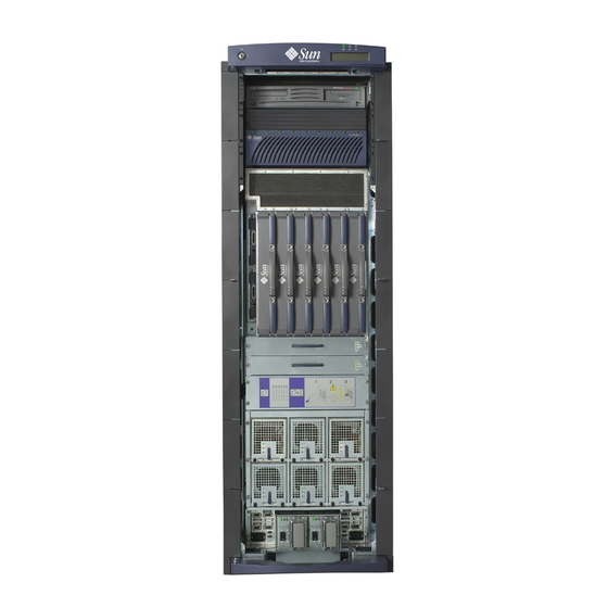
System Packaging This section describes the features of the system enclosures. A.2.1 Sun Fire E6900 System lists the parts of the system in the front view and rear view. TABLE A-1 Sun Fire E6900 System Components TABLE A-1 Front of the system Rear of the System Up to 6 CPU/Memory boards Up to 4 I/O assemblies... -
Page 155: Figure A-1 Sun Fire E6900 System-Front And Rear Views
Rear view Front view Sun Fire E6900 System—Front and Rear Views FIGURE A-1 Appendix A Functional Description... -
Page 156: Figure A-2 Sun Fire E4900 System-Front And Rear Views
A.2.2 Sun Fire E4900 System At the rear of the system there are slots for the following: Up to two I/O assemblies ■ Up to two System Controller boards ■ Two Repeater boards ■ Up to three CPU/Memory boards ■ Up to three fan trays ■... - Page 157 Software A.3.1 System Controller Software The system controller software is new to this product. Some of the functionality of the system controller software includes: Powering on boards, fan trays, power grids, or the entire system ■ Hot-plugging or hot-swapping components ■...
- Page 158 LEDs Keylock Beach ball MAC address 0003ba:de1abc Software release Maintenance wrench FrameManager Software Release 1.2 LCD Display FIGURE A-3 The FrameManager manages three LEDs: power, fault, and service ( TABLE A-3 FrameManager LED Functions TABLE A-3 Function Operation Activated LED Power On when the RTS has been commanded to enable (green)
- Page 159 Device Hot-Plug Procedures The power supplies and fan trays are hot-pluggable. When a device is hot- pluggable, it does not require intervention from the Solaris operating environment. As long as you power off the device using the system controller software and the amber OK to remove LED is lit, you can safely remove the device from the system.
-
Page 160: Figure A-4 Cpu/Memory Board With The Cover Removed
illustrates the CPU/Memory board with the CPU processor and Ecache FIGURE A-4 module cover removed. Note that two Ecache modules flank each side of the CPU processor. CPU/Memory Board With the Cover Removed FIGURE A-4 shows the CPU/Memory board slot locations. TABLE A-4 CPU/Memory Board Slot Locations TABLE A-4... -
Page 161: Table A-5 I/O Assembly Slot Locations
A.5.1 CPU Processors Each CPU/Memory board supports four CPU processors. If you do not have all four CPU processors installed, you must have a CPU processor filler panel to cover the unused CPU processor land area. This special filler panel prevents overheating of the installed CPU processors by creating an air baffle. -
Page 162: Figure A-5 Pci/Pci+/Pci-X I/O Assembly
When you remove the PCI I/O assembly to install components on it, you must install an PCI I/O assembly filler panel, which covers the assembly slot and prevents the system from overheating. The card slots in the PCI I/O assembly must have either a card or a filler board installed in them. - Page 163 shows a PCI card. FIGURE A-6 PCI Card FIGURE A-6 describes the PCI I/O assemblies. TABLE A-6 PCI I/O Assemblies TABLE A-6 I/O Assembly Description PCI I/O Assembly 8 PCI slots. The PCI I/O assembly has 6 slots for full-length PCI I/O cards and 2 short slots for short PCI I/O cards.
-
Page 164: Figure A-7 Power Supply For The Sun Fire E6900 Systems
The power supplies provide 55 VDC to the system controller, and 56 VDC is distributed to the fan trays. Current sharing between power supplies provides redundant power. Power Supply for the Sun Fire E6900 Systems FIGURE A-7 A-12 Sun Fire E6900/E4900 Systems Service Manual • May 2006... - Page 165 Power Supply for the Sun Fire E4900 System FIGURE A-8 Fan Trays All systems have fan trays that cool all components in the system. lists the TABLE A-8 number of fan trays in the systems. Number of Fan Trays, CPU Fan Trays, and Blower Assemblies TABLE A-8 System Type Total Number of Fan Trays and Blower Assemblies...
-
Page 166: Figure A-9 System Controller Board-E6900/E4900 Systems
System Controller Board The System Controller board contains the system clock and a system controller. One System Controller board is required per system. One additional System Controller board can be installed for redundancy in all systems. The System Controller board has the following features: Redundant System Controller board ■... -
Page 167: System Serial Number Locations And Rules For System Configuration
A P P E N D I X System Serial Number Locations and Rules for System Configuration Some of the following rules are suggestions for optimizing your system. Other rules are strictly required and are marked with the notation “Requirement” or “Maximum.”... -
Page 168: Figure B-1 Serial Number Location For The Sun Fire E6900 System-Rear
Serial number label location Serial Number Location for the Sun Fire E6900 System—Rear FIGURE B-1 Sun Fire E6900/E4900 Systems Service Manual • May 2006... -
Page 169: Figure B-2 Serial Number Location For The Sun Fire E4900 System-Rear
B.1.2 Location for the Sun Fire E4900 System The serial number location is in the rear of the system, on the side of the chassis, between the Repeater boards and the CPU/Memory boards. Serial number label location Serial Number Location for the Sun Fire E4900 System—Rear FIGURE B-2 Appendix B System Serial Number Locations and Rules for System Configuration... -
Page 170: Figure B-3 Sun Fire Cabinet System Serial Number Location-Rear
Serial number label location inside cabinet Sun Fire Cabinet System Serial Number Location—Rear FIGURE B-3 Sun Fire E6900/E4900 Systems Service Manual • May 2006... - Page 171 Boards and Assemblies B.2.1 CPU/Memory Boards 1. Requirement—Install CPU/Memory boards in their designated slots: Slots SB0–SB5 for the Sun Fire E6900 system ■ Slots SB0, SB2, and SB4 in the Sun Fire E4900 systems ■ 2. Requirement—For the Sun Fire E6900 system, the CPU/Memory boards are populated from right to left, beginning with SB5 and ending with SB0.
- Page 172 7. Requirement—If some CPU/Memory boards have more CPU processors than others, place DIMMs in DIMM banks on the board with the most CPU processors. There will be CPU processors without corresponding DIMMs on other boards. B.2.2 I/O Assemblies 1. Requirement—Install I/O assemblies in their designated slots: Slots IB6 –...
- Page 173 1. Requirement—Install CompactPCI filler cards in all empty CompactPCI slots. 2. Requirement—Install CompactPCI cards in their proper slots, 3.3V I/O cards in slots 0 and 1. B.2.3 Repeater Boards 1. Requirement—Install the Repeater boards in their designated slots: Slots RP0–RP3 in the Sun Fire E6900 system ■...
- Page 174 Filler Boards and Filler Panels For a description of the functionality of filler boards and filler panels, see Section 1.4, “Filler Boards and Filler Panels” on page 1-5. describes the rules you must TABLE B-1 follow when you hot-plug boards or devices, using filler boards and filler panels. Overheating Precautions Using Filler Panels and Filler Boards TABLE B-1 If you have...
- Page 175 Fan Trays Note – If the redundant fan tray is not installed, the other fans will run at high speed. This is normal operation, not an indication of a fault. 1. Requirement —You must replace a defective fan tray assembly in order to prevent the system from overheating in non-redundant configured systems.
- Page 176 Connecting Cables B.6.1 Ethernet The only Ethernet port is on the System Controller board. The Ethernet connector (RJ-45) allows access to the chassis port and the domain break shell with 10/100 Mbps Ethernet. To provide the system with external Ethernet connections, you must install a network I/O card in an I/O assembly.
-
Page 177: Illustrated Parts Breakdown
A P P E N D I X Illustrated Parts Breakdown This appendix lists and illustrates the replacement parts (field-replaceable units or FRUs) covered in this document and the jumper settings for the System Controller boards. List of Replacement Parts The following sections list the part numbers of the replacement parts for all systems, their part numbers, and illustrations. -
Page 178: Figure C-1 Sun Fire E6900 System-Front And Rear Views
C.1.1 Sun Fire E6900 System Replacement Parts Front view Rear view Sun Fire E6900 System—Front and Rear Views FIGURE C-1 Sun Fire E6900/E4900 Systems Service Manual • May 2006... -
Page 179: Table C-1 Sun Fire E6900 System Components
Sun Fire E6900 System Components TABLE C-1 Description System Controller board, SSC1 System Controller board, SSC0 Power supplies (up to 6), PS0 - PS5 Air inlet screen CPU/Memory boards w/ 2 CPUs, UltraSPARC IV CPU/Memory board, 0 MB memory CPU/Memory boards w/ 4 CPUs, UltraSPARC IV CPU/Memory board, 0 MB memory CPU/Memory boards w/ 2 CPUs, UltraSPARC IV+ CPU/Memory board, 0 MB memory... -
Page 180: Figure C-2 Sun Fire E6900 System Cabinet
Front view Rear view Sun Fire E6900 System Cabinet FIGURE C-2 Description FrameManager Fan trays (up to 2) RTS Module RTU Assembly EMI Clip (hidden by SB5, on right side of chassis) Sun Fire E6900/E4900 Systems Service Manual • May 2006... -
Page 181: Figure C-3 Sun Fire E4900 System-Rear View
C.1.2 Sun Fire E4900 System Replacement Parts Sun Fire E4900 System—Rear View FIGURE C-3 Sun Fire E4900 System—Rear View TABLE C-2 Description I/O assemblies (up to 2), IB6, IB8, PCI System Controller board, SSC1 System Controller board, SSC0 Fan tray, FT0 AC input box, AC Air outlet screen Appendix C Illustrated Parts Breakdown... - Page 182 Sun Fire E4900 System—Rear View TABLE C-2 Description CPU/Memory boards w/ 2 CPUs, UltraSPARC IV CPU/Memory board, 0 MB memory CPU/Memory boards w/ 4 CPUs, UltraSPARC IV CPU/Memory board, 0 MB memory CPU/Memory boards w/ 2 CPUs, UltraSPARC IV+ CPU/Memory board, 0 MB memory CPU/Memory boards w/ 4 CPUs, UltraSPARC IV+ CPU/Memory board, 0 MB memory...
-
Page 183: Figure C-4 Sun Fire E4900 System-Front View
Sun Fire E4900 System—Front View FIGURE C-4 Sun Fire E4900 System—Front View TABLE C-3 Description Fan tray, FT1 Power supplies (up to 3), PS0–PS2 Air inlet screen Centerplane ID source board Cable, system centerplane power Cable, fan, and I/O centerplane Appendix C Illustrated Parts Breakdown... -
Page 184: Figure C-5 Cpu/Memory Board
C.1.3 CPU/Memory Board Replacement Parts CPU/Memory Board FIGURE C-5 Description DIMMs Types of DIMMs TABLE C-4 Description Size DIMM 512–MByte DIMM 1–GByte DIMM 2–GByte Sun Fire E6900/E4900 Systems Service Manual • May 2006... -
Page 185: Figure C-6 Pci/Pci+/Pci-X I/O Assembly
C.1.4 I/O Assembly Replacement Parts PCI/PCI+/PCI-X I/O Assembly FIGURE C-6 Appendix C Illustrated Parts Breakdown... -
Page 186: Figure C-7 Repeater Board
C.1.5 Repeater Board Replacement Part Repeater Board FIGURE C-7 C-10 Sun Fire E6900/E4900 Systems Service Manual • May 2006... -
Page 187: Figure C-8 System Controller Board-E6900/E4900 Systems
C.1.6 System Controller Board System Controller Board—E6900/E4900 Systems FIGURE C-8 System Controller board (F501-5407) Jumper Settings Jumpers TABLE C-5 Jumper Pins Settings Description J1301 Select ROMBO J1301 Select FPROM (default) J1303 FPROM write enable (default) J1303 FPROM write protect J2303 RS232 J2303 RS423 (default) -
Page 188: Figure C-9 Power Supply For The Sun Fire E6900 Systems
C.1.7 Power Supply Replacement Parts Power Supply for the Sun Fire E6900 Systems FIGURE C-9 Power Supply for the Sun Fire E4900 System FIGURE C-10 C-12 Sun Fire E6900/E4900 Systems Service Manual • May 2006... -
Page 189: Table C-6 Filler Boards And Filler Panels Replacement Parts
Short PCI card filler board All systems Long PCI card filler board All systems Fan filler panel Sun Fire E4900 system Power supply filler panel Sun Fire E6900 systems Power supply filler panel Sun Fire E4900 system Appendix C Illustrated Parts Breakdown C-13... -
Page 190: Table C-7 Cable Replacement Parts
C.1.9 Cable Replacement Parts Cable Replacement Parts TABLE C-7 Cable System Cable, universal power cord Sun Fire E4900 system and Sun Fire cabinet Cable, universal power cord Y-splitter, 300 cm Sun Fire cabinet Cable, AC input power (North American, Asian), 350 Sun Fire E6900 system and Sun Fire cabinet Cable, AC input power (international), 350 cm Sun Fire E6900 system and Sun Fire cabinet... - Page 191 Glossary Central processing unit. An Ultra SPARC IV processor. CPU/Memory board The board containing up to four Ultra SPARC IV processors, eight Ecache modules, and four memory banks. DIMM Dual inline memory module. A small card with DRAM chips on its, used as main memory on the CPU/Memory board.
- Page 192 Sun Fire E6900 A 24-processor system installed in a cabinet. system Sun Fire E4900 system A 12-processor system. SRAM Static random access memory. A type of high-speed memory device used for Ecache modules. System Controller board A board containing a microSPARC® processor, which oversees operation of the system and provides clocks and the console bus.
- Page 193 Index power supply, 4-1 system, functional, A-1 assembly, I/O, 9-1 DIMMs, 8-13, 8-14 description, A-9 installing, 8-15 board maximizing performance, 8-14 CPU/Memory, 8-3 removing, 8-13 system controller, 7-2 rules, B-5 Dual inline memory modules, 8-13, 8-14 cable assembly, configuration, B-10 card, PCI, 9-10, 9-11 Ethernet, configuration, B-10 configuration rules for system, B-1...
- Page 194 Sun Fire 6800 system, 12-2 power supply I/O assembly, 9-1 description, 4-1, A-12 description, A-9 filler panel, Sun Fire 4800 system, 1-5, B-8 filler panel, B-8 LEDs, 4-5 handling, 9-2 installing, 9-9 precautions, system, 1-2 LEDs, 9-6 rules, B-6 installing removing CPU/Memory board, 8-10 DIMMs, 8-13...
Need help?
Do you have a question about the Fire E6900 Systems and is the answer not in the manual?
Questions and answers