Sign In
Upload
Manuals
Brands
Sun Microsystems Manuals
Desktop
SPARC classic X
Sun Microsystems SPARC classic X Manuals
Manuals and User Guides for Sun Microsystems SPARC classic X. We have
1
Sun Microsystems SPARC classic X manual available for free PDF download: Service Manual
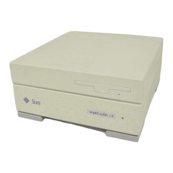
Sun Microsystems SPARC classic X Service Manual (198 pages)
Brand:
Sun Microsystems
| Category:
Desktop
| Size: 1.78 MB
Table of Contents
Table of Contents
3
Preface
15
Document Organization
15
12 Illustrated Parts Breakdown
16
1 Product Description
19
System Unit
19
FIGURE 1-1 Front Panel of the Sparcclassic and Sparcstation LX System Units
20
Main Logic Board
22
Memory Modules
23
Video SIMM
23
Sbus Cards
23
FIGURE 1-4 Typical DSIMM
23
FIGURE 1-5 Typical Sbus Card
24
Nonvolatile RAM (NVRAM)
24
Internal Diskette Drive
25
Internal Hard Disk Drive
25
Power Supply
25
Monitors, Keyboard, and Mouse
25
External Storage Devices
26
System Interconnections
26
2 Troubleshooting Overview
29
Default Boot Mode
29
Boot PROM Diagnostics
29
FIGURE 2-1 Default Boot Mode
31
Low-Level POST Code
32
Diagnostic Tools and When to Use Them
35
Power-On Self-Test
36
Selected On-Board Tests
36
Sundiag System Exerciser
37
Forth Toolkit
37
Sundiagnostic Executive
38
3 Power-On Self-Test (POST)
39
Power-On Self-Test (POST)
41
Normal Mode
42
Full Diagnostic Mode
42
Abbreviated Diagnostic Mode
42
Setting up a Tip Connection to Another Workstation
43
Tests the POST Runs
44
POST Error Messages
46
Status Lights (Leds) and Indicators
46
FIGURE 3-3 System Power LED on Front of System
46
FIGURE 3-4 Arrangement of the Type-5 Keyboard Leds
47
4 Troubleshooting Procedures
49
No Video Output on the System Monitor
50
Power-On Does Not Succeed
50
Power Supply Test
51
FIGURE 4-1 Power Supply Connector
52
System Board Test
53
Caps Lock Key Fails to Flash on and off During POST
53
Disk Drive Errors
54
Verifying the Built-In SCSI Controller
54
Determining Faulty DSIMM Locations
55
FIGURE 4-2 DSIMM Slot Locations
56
5 Safety and Tools Requirements
59
Safety Requirements
59
Symbols
60
System Precautions
61
Tools Required
61
6 Power off and on
63
Powering off the System
63
Powering off When the System Is Working Normally
63
Powering off When the System Does Not Respond Normally
65
Powering on the System
66
7 Internal Access
69
Disconnecting the External Cables
69
Opening the System Unit
70
Attaching the Wrist Strap
71
Closing the System Unit
72
FIGURE 7-2 Attaching the Wrist Strap
72
FIGURE 7-3 Closing the System Unit
74
Reconnecting the External Cables
75
8 Major Subassemblies
77
Power Supply
77
Removing the Power Supply
77
Replacing the Power Supply
79
FIGURE 8-1 Removing and Replacing the Power Supply
79
Speaker/Power LED Assembly
80
Removing the Speaker/Power LED Assembly
80
Replacing the Speaker/Power LED Assembly
82
FIGURE 8-2 Removing and Replacing the Speaker/Power LED Assembly
82
System I/O Board
83
Removing the System I/O Board
83
Replacing the System I/O Board
88
9 Storage Devices
91
Hard Disk Drive
91
Removing a Hard Disk Drive
92
Preparing a Hard Drive for Installation
93
Verifying the Jumper Settings
94
Installing a Hard Disk Drive
103
Disk Drive Bracket
105
Removing the Disk Drive Mounting Bracket
106
Replacing the Disk Drive Mounting Bracket
109
Diskette Drive
111
Removing the Diskette Drive
112
Replacing the Diskette Drive
113
10 System Board Overview
115
Before You Begin
115
Damage Prevention
116
Handling System Boards and Assemblies
116
Main Logic Board Layouts
118
Identifying Replaceable System Board Components
120
11 Main Logic Board and Component Replacement
123
Sbus Cards
123
Removing Sbus Cards
123
Replacing Sbus Cards
126
FIGURE 11-3 Positioning the Sbus Card
127
Video SIMM (VSIMM)
128
FIGURE 11-4 Connecting the Sbus Card
128
Removing the VSIMM
129
FIGURE 11-5 VSIMM Slot Location
130
FIGURE 11-6 Removing the VSIMM
131
Replacing the VSIMM
131
DRAM Single In-Line Memory Modules (Dsimms)
132
FIGURE 11-7 Installing the VSIMM
132
DSIMM Configurations
133
Removing a DSIMM
135
TABLE 11-1 Memory Configuration Matrix-Sparcclassic X Terminal
135
TABLE 11-2 Configuration Matrix for Memory Modules
135
FIGURE 11-10 Removing a DSIMM
137
Replacing a DSIMM
137
Main Logic Board
139
FIGURE 11-11 Installing a DSIMM
139
Main Logic Board Voltage Test Points
140
Before Replacing the Main Logic Board
143
Removing the Main Logic Board
146
FIGURE 11-15 Extracting the Main Logic Board
149
FIGURE 11-16 Raising the Speaker/Led Assembly
149
FIGURE 11-17 Removing and Replacing the Main Logic Board
150
Installing the New Main Logic Board
151
FIGURE 11-18 Plugging in the Main Logic Board
152
Removing the NVRAM
153
FIGURE 11-19 Locating the NVRAM
154
FIGURE 11-20 Removing the NVRAM
154
FIGURE 11-21 Default Sparcstation LX ISDN Jumper Settings
155
Replacing the NVRAM
155
TABLE 11-3 Sparcstation LX ISDN Jumper Settings
156
Illustrations of Selected Crus
157
FIGURE 12-1 Exploded View of the Unit Top
158
FIGURE 12-2 Exploded View of the Unit Bottom
159
TABLE 12-1 Part Number List-Customer Replaceable Units
161
TABLE 12-2 Part Number List-Miscellaneous Items
163
TABLE 12-3 Part Number List-Related Hardware Documentation
163
TABLE A-1 Input Power Requirements and Power Dissipation
165
TABLE A-2 Environmental Requirements
166
A.3 Physical Specifications
167
System Connectors
169
FIGURE B-1 Attachment Unit Interface (AUI) Connector
170
TABLE B-1 Pinout for Attachment Unit Interface (AUI) Connector
170
FIGURE B-2 Twisted-Pair Ethernet Connector
171
FIGURE B-3 ISDN Terminal Endpoint Connector
171
TABLE B-2 Pinout for Twisted-Pair Ethernet Connector
171
TABLE B-3 Pinout for ISDN Terminal Endpoint Connector
171
FIGURE B-4 ISDN Network Termination Connector
172
TABLE B-4 Pinout for ISDN Network Termination Connector
172
FIGURE B-5 Keyboard/Mouse Connector
173
TABLE B-5 Pinout for Keyboard/Mouse Connector
173
FIGURE B-6 External SCSI Connector
174
TABLE B-6 Pinout for External SCSI Connector
174
B.6 SCSI Connector (External)
174
FIGURE B-7 Serial Connector
175
TABLE B-7 Pinout for Serial Connector
175
FIGURE B-8 Parallel Connector
176
TABLE B-8 Pinout for Parallel Connector
176
FIGURE B-9 13W3 Video Connector
177
TABLE B-9 Pinout for 13W3 Video Connector
177
FIGURE B-10 Audio Ports
178
FIGURE B-11 Audio Line-Out Connector
178
FIGURE B-12 Audio Line-In Connector
178
TABLE B-10 Audio Ports
178
B.11 Signals for the Audio Ports
178
FIGURE B-13 Internal SCSI Connector
179
TABLE B-11 Pinout for Internal SCSI Connector
179
B.12 SCSI Connector (Internal)
179
FIGURE B-15 Sbus Connector
181
TABLE B-13 Pinout for Sbus Connector
181
FIGURE B-16 Power Connector
182
TABLE B-14 Pinout for Power Connector
182
Advertisement
Advertisement
Related Products
Sun Microsystems SPARCclassic
Sun Microsystems SPARCclassic X
Sun Microsystems SPARC station LX
Sun Microsystems Sun-1
Sun Microsystems Sun-3/260
Sun Microsystems Sun-3/60
Sun Microsystems SPARCstation 20
Sun Microsystems SPARCstation Voyager
Sun Microsystems SPARCstation LX
Sun Microsystems SPARCcenter 2000
Sun Microsystems Categories
Server
Storage
Desktop
Computer Hardware
Adapter
More Sun Microsystems Manuals
Login
Sign In
OR
Sign in with Facebook
Sign in with Google
Upload manual
Upload from disk
Upload from URL