Sign In
Upload
Manuals
Brands
Omron Manuals
Servo Drives
G5 Series
Omron G5 Series Manuals
Manuals and User Guides for Omron G5 Series. We have
3
Omron G5 Series manuals available for free PDF download: User Manual, Startup Manual
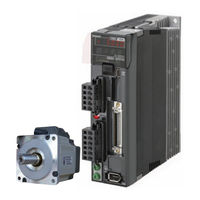
Omron G5 Series User Manual (506 pages)
AC Servomotors/Servo Drives. Pulse-train Input Type
Brand:
Omron
| Category:
Servo Drives
| Size: 18.33 MB
Table of Contents
Introduction
5
Read and Understand this Manual
6
Safety Precautions
9
Items to Check after Unpacking
17
Revision History
18
Manual Configuration
19
Manual Structure
20
Contents
23
Sections in this Manual
23
Features and System Configuration
23
Table of Contents
24
Outline
30
Outline of OMNUC G5-Series Servo Drives (Pulse-Train Input Type)
30
Features of OMNUC G5-Series Servo Drives (Pulse-Train Input Type)
30
System Configuration
31
Names and Functions
32
Servo Drive Part Names
32
Servo Drive Functions
33
System Block Diagram
34
Applicable Standards
38
EC Directives
38
UL and Cul Standards
38
Semi F47
38
Models and External Dimensions
39
Section 2 Models and External Dimensions
40
Servo System Configuration
40
How to Read Model Numbers
42
Servo Drive
42
Servomotor
43
Decelerator (Backlash: 3 Arcminutes Max.)
44
Decelerator (Backlash: 15 Arcminutes Max.)
45
Model Tables
46
Servo Drive Model Table
46
Servomotor Model Tables
46
Servo Drive and Servomotor Combination Tables
49
Decelerator Model Tables
50
Cable and Peripheral Device Model Tables
54
External and Mounting Dimensions
60
Servo Drive Dimensions
60
Servomotor Dimensions
69
Combinations of Servomotors and Decelerators
78
Decelerator Dimensions
80
External Regeneration Resistor Dimensions
94
Reactor Dimensions
95
Mounting Bracket (L-Brackets for Rack Mounting) Dimensions
99
Specifications
101
Servo Drive Specifications
102
General Specifications
102
Characteristics
103
Main Circuit and Motor Connections
106
Control I/O Connector Specifications (CN1)
109
Control Input Circuits
115
Control Input Details
117
Control Output Circuits
127
Control Output Details
128
Encoder Connector Specifications (CN2)
132
Analog Monitor Connector Specifications (CN5)
133
USB Connector Specifications (CN7)
134
Overload Characteristics (Electronic Thermal Function)3-35
135
Overload Characteristics Graphs
135
Overload Characteristics (Electronic Thermal Function)
135
Servomotor Specifications
136
General Specifications
136
Characteristics
137
Encoder Specifications
153
Decelerator Specifications
154
Models and Specifications
154
Cable and Connector Specifications
162
Resistance to Bending of Global Flexible Cable
162
Encoder Cable Specifications
164
Motor Power Cable Specifications
168
Connector Specifications
180
Analog Monitor Cable Specifications
183
Control Cable Specifications
184
Servo Relay Unit and Cable Specifications
196
Servo Relay Unit Specifications
196
Servo Drive Relay Unit Cable Specifications
208
Position Control Unit Relay Unit Cable Specifications
211
External Regeneration Resistor Specifications
222
Reactor Specifications
224
System Design
225
Installation Conditions
226
Servo Drive Installation Conditions
226
Servomotor Installation Conditions
227
Decelerator Installation Conditions
230
Wiring
234
Peripheral Equipment Connection Examples
234
Main Circuit and Motor Connections
238
Wiring Conforming to EMC Directives
244
Wiring Method
244
Selecting Connection Components
250
Regenerative Energy Absorption
263
Calculating the Regenerative Energy
263
Servo Drive Regeneration Absorption Capacity
265
Regenerative Energy Absorption with an External Regeneration Resistor
266
Connecting an External Regeneration Resistor
267
Section 5 Basic Control Mode
270
Position Control
270
Outline of the Function
270
Parameters Requiring Settings
271
Related Functions
273
Parameter Block Diagram for Position Control Mode
274
Internally Set Speed Control
275
Outline of the Function
275
Parameters Requiring Settings
275
Related Functions
279
Parameter Block Diagram for Speed Control Mode
280
Switching Control
281
Outline of the Function
281
Parameters Requiring Settings
281
Related Functions
282
Applied Functions
283
Section 6 Applied Functions
285
Damping Control
285
Outline of the Function
285
Parameters Requiring Settings
285
Adaptive Filter
288
Outline of the Function
288
Parameters Requiring Settings
289
Notch Filters
290
Outline of the Function
290
Parameters Requiring Settings
291
Electronic Gear Function
293
Outline of the Function
293
Parameters Requiring Settings
293
Operation Example
295
Encoder Dividing Function
297
Outline of the Function
297
Parameters Requiring Settings
297
Brake Interlock
300
Outline of the Function
300
Parameters Requiring Settings
300
Precautions for Correct Use of Holding Brake
300
Operation
301
Operation
303
Gain Switching Function
305
Outline of the Function
305
Parameters Requiring Settings
306
Torque Limit
313
Outline of the Function
313
Sequence I/O Signals
315
Outline of the Function
315
Input Signals
315
Output Signals
318
Forward and Reverse Drive Prohibition Functions
320
Outline of the Function
320
Parameters Requiring Settings
320
Disturbance Observer Function
323
Outline of the Function
323
Parameters Requiring Settings
324
Operating Procedure
324
Gain 3 Switching Function
325
Outline of the Function
325
Parameters Requiring Settings
325
Operation
325
Friction Torque Compensation Function
326
Outline of the Function
326
Parameters Requiring Settings
326
Operation Example
327
Inertia Ratio Switching Function
328
Outline of the Function
328
Parameters Requiring Settings
328
Operating Procedure
328
Feed-Forward Function
329
Outline of the Function
329
Parameters Requiring Settings
329
Operating Procedure
330
Instantaneous Speed Observer Function
332
Outline of the Function
332
Parameters Requiring Settings
332
Operating Procedure
333
Parameter Details
335
Basic Parameters
336
Gain Parameters
344
Vibration Suppression Parameters
354
Analog Control Parameters
360
Interface Monitor Setting Parameters
366
Extended Parameters
376
Special Parameters
389
Operation
397
Operational Procedure
398
Preparing for Operation
399
Items to Check before Turning on the Power Supply
399
Turning on the Power Supply
400
Checking the Display
400
Using the Front Panel Display
401
Mode Setting
402
Changing the Mode
402
Monitor Mode
403
Parameter Setting Mode
415
Parameter Write Mode
417
Auxiliary Function Mode
418
Trial Operation
424
Preparations for Trial Operation
424
Trial Operation in Position Control Mode
425
Adjustment Functions
427
Section 9 Adjustment Functions
428
Gain Adjustment
428
Purpose of the Gain Adjustment
428
Gain Adjustment Methods
428
Gain Adjustment Procedure
429
Realtime Autotuning
430
Setting Realtime Autotuning
431
Setting Machine Rigidity
431
Manual Tuning
437
Basic Settings
437
Troubleshooting and Maintenance
445
Actions for Problems
446
Preliminary Checks When a Problem Occurs
446
Precautions When a Problem Occurs
447
Replacing the Servomotor or Servo Drive
448
Warning List
449
Alarm List
450
Troubleshooting
454
Error Diagnosis with Alarm Displays
454
Error Diagnosis Using the Operation State
461
Periodic Maintenance
465
Servomotor Life Expectancy
465
Servo Drive Life Expectancy
466
Appendices
467
A-1 Connection Examples
467
Parameter List
477
Advertisement
Omron G5 Series Startup Manual (52 pages)
Programmable Multi-Axis Controller
Brand:
Omron
| Category:
Servo Drives
| Size: 1.98 MB
Table of Contents
Table of Contents
3
Related Manuals
4
Terms and Definitions
5
Precautions
6
Overview
7
Applicable Devices and Device Configuration
8
Applicable Devices
8
Device Configuration
9
Ethercat Connection Procedure
10
Workflow
10
Preparation for the Controller Setup
12
Installation of ESI Files
17
Ethercat Communications Setup
18
Controller Settings
27
Appendix Saving and Loading a Project
39
Saving a Project
39
Loading and Downloading a Project
41
Appendix Troubleshooting
44
Factors Causing Ethercat Communications to be Unavailable, and Corrective Actions
44
How to Check for Errors
45
Appendix Ecat[I] Structure Elements
48
Revision History
49
Omron G5 Series Startup Manual (47 pages)
Programmable Multi-Axis Controller, Servo Drivers, IDEv4
Brand:
Omron
| Category:
Servo Drives
| Size: 1.79 MB
Table of Contents
Table of Contents
3
1 Related Manuals
4
2 Terms and Definitions
5
3 Precautions
6
4 Overview
7
5 Applicable Devices and Device Configuration
8
Applicable Devices
8
Device Configuration
9
6 Ethercat Connection Procedure
10
Workflow
10
Preparation for the Controller Setup
12
Installation of ESI Files
17
Ethercat Communications Setup
17
Controller Settings
25
7 Appendix Saving and Loading a Project
36
Saving a Project
36
Loading and Downloading a Project
38
8 Appendix Troubleshooting
41
Factors Causing Ethercat Communications to be Unavailable, and Corrective Actions
41
How to Check for Errors
42
9 Appendix Ecat[I] Structure Elements
45
10 Revision History
46
Advertisement
Advertisement
Related Products
Omron G5 R88M-KP Series
Omron OMNUC G5 R88D-KT01H
Omron OMNUC G5 R88D-KT08H
Omron OMNUC G5 R88D-KT10H
Omron OMNUC G5 R88D-KT50H
Omron OMNUC G5 R88D-KT75H
Omron OMNUC G5 R88D-KT150H
Omron OMNUC G5 R88D-KT06F
Omron OMNUC G5 R88D-KT15F
Omron OMNUC G5 R88D-KT75F
Omron Categories
Blood Pressure Monitor
Controller
Accessories
Switch
Inverter
More Omron Manuals
Login
Sign In
OR
Sign in with Facebook
Sign in with Google
Upload manual
Upload from disk
Upload from URL