Sign In
Upload
Manuals
Brands
Omron Manuals
Servo Drives
OMNUC G5 R88D-KT15F
Omron OMNUC G5 R88D-KT15F Manuals
Manuals and User Guides for Omron OMNUC G5 R88D-KT15F. We have
1
Omron OMNUC G5 R88D-KT15F manual available for free PDF download: User Manual
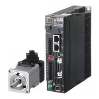
Omron OMNUC G5 R88D-KT15F User Manual (632 pages)
AC SERVOMOTORS/SERVO DRIVES
Brand:
Omron
| Category:
Servo Drives
| Size: 42.98 MB
Table of Contents
Table of Contents
20
Safety Precautions
8
Items to Check after Unpacking
16
Revision History
17
Structure of this Document
18
Table of Contents
20
Chapter 1 Features and System Configuration
24
Outline
24
Features of OMNUC G5-Series Servo Drives
24
Outline of the OMNUC G5 Series
24
System Configuration
25
Names and Functions
26
Servo Drive Part Names
26
Servo Drive Functions
27
System Block Diagrams
28
Applicable Standards
38
EC Directives
38
UL and Cul Standards
38
Korean Radio Regulations (KC)
39
Semi F47
40
Unit Versions
41
Confirmation Method
41
Standard Models and External Dimensions
43
Chapter 2 Standard Models and External Dimensions
44
Servo System Configuration
44
How to Read Model Numbers
46
Servo Drive
46
Servomotor
47
Standard Model Tables
48
Servo Drive Model Table
48
Servomotor Model Tables
49
Servo Drive and Servomotor Combination Tables
54
Peripheral Equipment and Cable Model Tables
56
External and Mounting Dimensions
68
Servo Drive Dimensions
68
Servomotor Dimensions
86
External Regeneration Resistor Dimensions
113
EMC Filter Dimensions
114
Dimensions of Mounting Brackets (L-Brackets for Rack Mounting)
115
Specifications
117
Chapter 3 Specifications
118
Servo Drive Specifications
118
General Specifications
118
Characteristics
119
Main Circuit and Motor Connections
126
Control I/O Connector Specifications (CN1)
135
Control Input Circuits
145
Control Input Details
149
Control Output Circuits
162
Control Output Details
163
Encoder Connector Specifications (CN2)
168
External Encoder Connector Specifications (CN4)
168
Analog Monitor Connector Specifications (CN5)
171
Safety Connector Specifications (CN8)
172
USB Connector Specifications (CN7)
172
Overload Characteristics (Electronic Thermal Function)
175
Overload Characteristics Graphs
175
Servomotor Specifications
176
General Specifications
176
Characteristics
177
Encoder Specifications
213
Cable and Connector Specifications
214
Encoder Cable Specifications
214
Motor Power Cable Specifications
217
Connector Specifications
224
Analog Monitor Cable Specifications
228
Control Cable Specifications
229
Servo Relay Units and Cable Specifications
244
Servo Relay Units and Cable Specifications
246
Position Control Unit-Servo Relay Unit Cable Specifications
253
External Regeneration Resistor Specifications
263
EMC Filter Specifications
265
System Design
267
Chapter 4 System Design
268
Installation Conditions
268
Space Conditions Around Servo Drives
268
Servomotor Installation Conditions
270
Decelerator Installation Conditions
273
Wiring
274
Peripheral Equipment Connection Examples
275
Main Circuit and Motor Connections
285
Wiring Conforming to EMC Directives
300
Wiring Method
300
Selecting Connection Component
308
Regenerative Energy Absorption
320
Regenerative Energy Calculation
320
Servo Drive Regeneration Absorption Capacity
323
Regenerative Energy Absorption with an External Regeneration Resistor
324
Connecting an External Regeneration Resistor
325
Large Load Inertia Adjustment and Dynamic Brake
328
Adjustment When the Load Inertia Is Large
328
Dynamic Brake When the Load Inertia Is Large
328
Using DC Power
329
Connection Examples for DC Power
330
Chapter5 Basic Control Mode
333
Position Control
334
Speed Control
340
Torque Control
347
Internally Set Speed Control
352
Switching Control
356
Fully-Closed Control
359
Chapter6 Applied Functions
369
Damping Control
371
Adaptive Filter
375
Notch Filter
377
Electronic Gear Function
380
Encoder Dividing Function
384
Brake Interlock
389
Gain Switching Function
394
Torque Limit
402
Sequence I/O Signal
405
Forward and Reverse Drive Prohibition Functions
411
Disturbance Observer Function
414
Gain Switching 3 Function
416
Friction Torque Compensation Function
417
Inertia Ratio Switching Function
419
Hybrid Vibration Suppression Function
420
Feed-Forward Function
421
Instantaneous Speed Observer Function
425
Chapter7 Safety Function
427
Safe Torque off (STO) Function
428
Operation Example
431
Connection Example
433
Chapter8 Parameter Details
435
Basic Parameters
436
Gain Parameters
444
Vibration Suppression Parameters
455
Analog Control Parameters
460
Interface Monitor Setting Parameters
472
Extended Parameters
482
Special Parameters
495
Chapter9 Operation
504
Operational Procedure
504
Preparing for Operation
505
Using the Front Display
509
Setting the Mode
510
Trial Operation
536
Chapter10 Adjustment Functions
541
Gain Adjustment
542
Realtime Autotuning
544
Manual Tuning
551
Chapter11 Troubleshooting And Maintenance
559
Troubleshooting
560
Warning List
563
Alarm List
564
Troubleshooting
569
Periodic Maintenance
586
Chapter12 Appendix
591
Connection Examples
592
Parameter List
602
Advertisement
Advertisement
Related Products
Omron OMNUC G5 R88D-KT10H
Omron OMNUC G5 R88D-KT15H
Omron OMNUC G5 R88D-KT150H
Omron OMNUC G5 R88D-KT10F
Omron OMNUC G5 R88D-KT150F
Omron OMNUC G5 R88D-KT01H
Omron OMNUC G5 R88D-KT08H
Omron OMNUC G5 R88D-KT50H
Omron OMNUC G5 R88D-KT75H
Omron OMNUC G5 R88D-KT06F
Omron Categories
Blood Pressure Monitor
Controller
Accessories
Switch
Inverter
More Omron Manuals
Login
Sign In
OR
Sign in with Facebook
Sign in with Google
Upload manual
Upload from disk
Upload from URL