Sign In
Upload
Manuals
Brands
OMRON Manuals
Controller
E5AK
OMRON E5AK Manuals
Manuals and User Guides for OMRON E5AK. We have
6
OMRON E5AK manuals available for free PDF download: User Manual, Manual, Datasheet
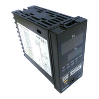
OMRON E5AK User Manual (177 pages)
Digital Controller
Brand:
OMRON
| Category:
Controller
| Size: 2 MB
Table of Contents
How to Read Display Symbols
3
Meanings of Abbreviations
3
“Reference” Mark
3
Notice
4
Table of Contents
7
Introduction
9
Table of Contents
9
Chapter 1 Introduction
10
Names of Parts
10
Main Parts
10
Front Panel
10
About the Displays
11
How to Use Keys
11
Bar Graph
11
Input and Output
12
Remote SP Input
12
Temperature Input/Voltage Input/Current Input
12
Event Input
13
Output
13
Transfer Output
14
Manual Mode
15
Parameter Types
15
Parameters and Menus
15
Protect Mode
15
Specifications
15
Calibration Mode
16
Menu Display
16
Output
16
Selecting Modes
16
Fixing Settings
17
Selecting Parameters
17
About the Communications Function
18
About Calibration
19
Calibrating Inputs
19
Calibrating Transfer Output
19
Registering Calibration Data
19
Preparations
21
Chapter 2 Preparations
22
Setting up
22
Draw-Out
22
Setting up the Output Unit
23
Before Setup
23
Setting up the Option Unit
24
Dimensions
25
Installation
25
Panel Cutout
25
Mounting
26
Setting up the Terminal Covers
27
Precautions When Wiring
28
Terminal Arrangement
28
Wiring
28
Wiring Terminals
28
Control Output
29
Sensor Input
29
Specifications
29
Wiring Terminals
29
Auxiliary Output
30
CT Input
30
Potentiometer
30
Basic Operation
33
Chapter 3 Basic Operation
34
Convention Used in this Chapter
34
Setup
35
Input Shift
36
Input Type
36
Scaling
36
Setting Input Specifications
36
Input Type
37
Setting Example
37
Output Assignments
38
Setting Output Specifications
38
Standard Type
38
Control Period
39
Direct/Reverse
39
Control Period
40
Direct/Reverse Operation
40
Alarm Type
41
Alarm Value
41
Setting Alarm Type
41
Alarm Hysteresis
42
Alarm Value
42
Close in Alarm/Open in Alarm
42
Summary of Alarm Operations
42
A/M Key Protect
44
Protect Mode
44
Security
44
Starting and Stopping Operation
45
Adjusting Control Operation
46
Changing the Set Point
46
Manual Operation
46
Position-Proportional Type
47
Auto-Tuning
48
Applied Operation
51
Selecting the Control Method
52
Cooling Coefficient
52
Chapter 4 Applied Operation
52
Heating and Cooling Control
52
Manual Operation
52
Position-Proportional Control
53
ON/OFF Control
53
Travel Time
53
Valve Opening Monitor
53
Hysteresis
54
Manipulated Variable Restrictions
55
MV Change Rate Limiter
55
MV Limiter
55
Operating Condition Restrictions
55
Limiter Operation Conditions
56
Set Point Limiter
56
SP Ramp
56
Operation at Start
57
Restrictions During SP Ramp
57
Event Input Assignments
58
How to Use Event Input
58
Multi-SP
58
Multi-SP
59
Auto/Manual
60
Other Event Input Functions
60
Remote/Local
60
Run/Stop
60
How to Use the Remote SP
61
SP Mode
61
Operating Conditions
62
Remote SP Monitor
62
SP Tracking
62
HBA Latch/Release
63
Heater Burnout Detection
63
How to Use the Heater Burnout Alarm
63
Operating Conditions
63
Examples of Use
64
How to Calculate the Heater Burnout Set Value
64
When Using a 200 VAC, 1 Kw Heater
64
When Using Three 200 VAC, 1 Kw Heaters
64
Lba
65
LBA Detection Example
65
LBA Detection Time
65
LBA Detection Width
65
Determining the LBA Detection Time
66
Setting the LBA Detection Time
66
How to Use Transfer Output
67
Transfer Output Type
67
Transfer Output Scaling
67
Parameters
69
The Meaning of Icons Used in this Chapter
70
About Parameter Display
70
Manual MV
73
Level 0 Mode
74
Pv/Sp
74
Set Point During SP Ramp
76
MV Monitor (Heat)
76
MV Monitor (Cool)
76
Level 1 Mode
78
AT Execute/Cancel
79
Set Point 0
79
Set Point 1
79
Set Point 2
79
Alarm Value 1
80
Alarm Value 2
80
Alarm Value 3
80
Proportional Band
81
Integral Time
81
Derivative Time
81
Dead Band
82
Position-Proportional Dead Band
82
Manual Reset Value
83
Hysteresis (Heat)
83
Hysteresis (Cool)
83
Control Period (Heat)
84
Control Period (Cool)
84
Heater Current Monitor
85
Heater Burnout
85
Level 2 Mode
86
SP Mode
87
SP Ramp Time Unit
88
SP Ramp Set Value
88
MV at Stop
89
MV at PV Error
89
MV Upper Limit
90
MV Lower Limit
90
MV Change Rate Limit
90
Input Digital Filter
91
Open/Close Hysteresis
91
Alarm 1 Hysteresis
92
Alarm 2 Hysteresis
92
Alarm 3 Hysteresis
92
Input Shift Upper Limit
92
Scaling Upper Limit
95
Scaling Lower Limit
95
Decimal Point
95
Parameter Initialize
95
_C/_F Selection
96
Auxiliary Output 1 Assignment
97
Auxiliary Output 2 Assignment
97
Alarm 1 Type
98
Alarm 2 Type
98
Alarm 3 Type
98
Alarm 1 Open in Alarm
99
Alarm 2 Open in Alarm
99
Alarm 3 Open in Alarm
99
Direct/Reverse Operation
99
Expansion Mode
100
Set Point Upper Limit
101
Set Point Lower Limit
101
Pid / On/Off
101
St
102
ST Stable Range
102
AT Calculated Gain
103
Standby Sequence Reset Method
103
Automatic Return of Display Mode
104
AT Hysteresis
104
Option Mode
105
Multi-SP Function
106
Event Input Assignment 1
107
Communication Stop Bit
108
Communication Parity
108
Communication Baud Rate
108
Transfer Output Upper Limit
109
Transfer Output Lower Limit
109
HBA Latch
110
Motor Calibration
110
PV Dead Band
111
Remote SP Enable
112
Remote SP Upper Limit
112
Remote SP Lower Limit
112
SP Tracking Enable
113
Using the Communications Function
115
Chapter 6 Using the Communications Function
116
Outline of the Communications Function
116
Interface
116
Transfer Procedure
116
Cable Connections
117
Preparing for Communications
117
Rs-422
117
Communications Parameters
118
Rs-485
118
Setting the Communications Specifications
118
Command Code
119
Command Configuration
119
Command Type
119
End Code
119
Commands and Responses
120
Reading/Writing Parameters
120
Command List
124
Issuing Special Commands
124
End Code
126
How to Read Communications Error Information
126
Undefined Error
127
Program Example
128
How to Use Programs
128
Conditions When Running a Program
128
Program List
129
Start Running
130
Monitor Process Value
130
Calibration
131
Structure of Parameters
132
Calibration Item Menu
133
Calibration Save Mark
133
Calibrating Thermocouple
134
Calibrating Platinum Resistance Thermometer
137
Calibrating Current Input
139
Calibrating Voltage Input
140
Checking Indication Accuracy
142
Troubleshooting
145
Initial Checks
146
How to Use the Error Display
147
Input Error
147
Memory Error
147
A/D Converter Error
147
Calibration Data Error
148
Display Range over
148
Motor Calibration Error (Displayed on the No. 2 Display)
148
How to Use Error Output
149
Checking Operation Restrictions
150
Ratings
152
Appendix
152
Specifications
152
Characteristics
153
Heater Burnout Alarm
153
Option Unit Ratings and Characteristics
154
Output Unit Ratings and Characteristics
154
About Current Transformer (Ct)
155
Control Block Diagram
156
Setting List
158
Model List
161
Parameter Operations List
162
Fuzzy Self- -Tuning Function
164
Fuzzy Self-Tuning
164
Balanced Status
165
PID Constant
165
Stable Temperature Status
165
Startup Conditions of DT
166
Startup Conditions of HT
166
Format
167
Response
167
Header Code/Data Code
167
X Format Head List
168
RX (Process Value Read) Command Status
169
Ascii Code List
170
Index
171
Advertisement
Omron E5AK User Manual (177 pages)
E5AK Series Digital Controller
Brand:
Omron
| Category:
Controller
| Size: 2 MB
Table of Contents
Table of Contents
8
User Manual
1
Conventions Used in this Manual
4
Chapter 1 Introduction
6
Chapter 2 Preparations
6
Chapter 3 Basic Operation
6
Chapter 4 Applied Operation
6
Troubleshooting
6
Pay Attention to the Following When Installing this Controller
7
Table of Contents
8
Names of Parts
11
Main Parts
11
Front Panel
11
About the Displays
12
How to Use Keys
12
Input and Output
13
Parameters and Menus
16
Parameter Types
16
Selecting Modes
17
Menu Display
17
Selecting Parameters
18
Fixing Settings
18
Manual Mode
18
About the Communications Function
19
About Calibration
20
Setting up
23
Setting up the Output Unit
24
Setting up the Option Unit
25
Before Setup
25
Panel Cutout
26
Setting up the Terminal Covers
28
Terminal Arrangement
29
Power Supply
29
Chapter 3 Chapter 3 Basic Operation
34
Basic Operation
35
Convention Used in this Chapter
35
Setting Input Specifications
37
Input Type
38
Setting Output Specifications
39
Output Assignments
39
Direct/Reverse Operation
39
Control Period
39
Setting Alarm Type
42
Alarm Type
42
Alarm Value
43
Alarm Hysteresis
43
Alarm Hysteresis
44
Close in Alarm/Open in Alarm
44
Protect Mode
45
Security
45
A/M Key Protect
45
Starting and Stopping Operation
46
Adjusting Control Operation
47
Changing the Set Point
47
Chapter 4 Chapter 4 Applied Operation
52
Manual Operation
53
Selecting the Control Method
53
Heating and Cooling Control
53
Position-Proportional Control
54
ON/OFF Control
54
Operating Condition Restrictions
56
Set Point Limiter
57
Sp Ramp
57
Manipulated Variable Restrictions
58
SP Ramp
58
How to Use Event Input
59
Event Input Assignments
59
Multi-SP
59
Other Event Input Functions
61
How to Use the Remote SP
62
Scaling
62
SP Mode
63
Remote SP Monitor
63
SP Tracking
63
Operating Conditions
63
How to Use the Heater Burnout Alarm
64
Heater Burnout Detection
65
The Heater Burnout Set Value
65
Lba
66
Lba Detection Time
67
How to Use Transfer Output
68
About Parameter Display
71
Conventions Used in this Chapter
71
A/M] Key Protect
73
Manual Mode
74
Manual MV
74
Remote Sp Monitor
76
MV Monitor (Heat)
77
Set Point During Sp Ramp
77
At Execute/Cancel
80
Set Point
80
Integral Time
82
Proportional Band
82
Dead Band
83
Hysteresis (Heat)
84
Manual Reset Value
84
Heater Burnout
86
Heater Current Monitor
86
Sp Ramp Set Value
89
MV at Pv Error
90
MV Change Rate Limit
91
Input Digital Filter
92
Chapter 5 Parameters
95
Setup Mode
96
Decimal Point
96
Parameter Initialize
96
Control Output 2 Assignment
97
Auxiliary Output 1 Assignment
98
Auxiliary Output 2 Assignment
98
Alarm 1 Type
99
Alarm 2 Type
99
Direct/Reverse Operation
100
Set Point Upper Limit
102
Set Point Lower Limit
102
Standby Sequence Reset Method
104
Automatic Return of Display Mode
105
Event Input Assignment
108
Transfer Output Upper Limit
110
Transfer Output Lower Limit
110
Remote Sp Lower Limit
113
Chapter 6 Chapter 6 Using the Communications Function
116
Communications Function
116
Outline of the Communications Function
117
Cable Connections
118
Preparing for Communications
118
Setting the Communications Specifications
119
Command Configuration
120
Commands and Responses
121
Reading/Writing Parameters
121
Command List
125
Issuing Special Commands
125
How to Read Communications Error Information
127
End Code
127
Undefined Error
128
Conditions When Running a Program
129
Examples of Use
131
Set the Set Point to
131
How to Use Programs
129
Program Example
129
Start Running
131
Structure of Parameters
133
Calibrating Thermocouple
135
Chapter 7 Calibration
138
Calibrating Platinum Resistance Thermometer
138
Calibrating Current Input
140
Calibrating Voltage Input
141
Checking Indication Accuracy
143
Initial Checks
147
How to Use the Error Display
148
Input Error
148
Memory Error
148
Calibration Data Error
149
Display Range over
149
How to Use Error Output
150
Checking Operation Restrictions
151
Appendix
152
Specifications
153
Heter Burnout Alarm
154
About Current Transformer (Ct)
156
Control Block Diagram
157
Standard Type
157
Setting List
159
Model List
162
Parameter Operations List
163
Fuzzy Self-Tuning
165
Balanced Status
166
Stable Temperature Status
166
Startup Conditions of Dt
167
Startup Conditions of Ht
167
Format
168
X Format Head List
169
Ascii Code List
171
Symbols
172
Chapter 8 Troubleshooting
176
Revision History
176
Revision Code
176
OMRON E5AK User Manual (203 pages)
Digital Controller (Programmable Type)
Brand:
OMRON
| Category:
Controller
| Size: 2 MB
Table of Contents
Table of Contents
8
Conventions Used in this Manual
3
Precautions on Safety
5
Table of Contents
8
Chapter 1 Introduction
11
Names of Parts
12
Main Parts
12
Front Panel
12
About the Displays
13
How to Use Keys
14
Input and Output
15
Program
18
Parameters and Menus
19
About the Communications Function
22
About Calibration
23
Input
23
Chapter 2 Preparations
25
Setup
26
Installation
29
Wiring Terminals
32
Output 1
34
Chapter 3 Chapter 3 Basic Operation
37
Convention Used in this Chapter
38
Setting Input Specifications
40
Input Type
40
Temperature Input
40
Analog Input
41
Setting Output Specifications
43
Output Assignments
43
Direct/Reverse Operation
45
Control Period
45
Setting Alarm Type
46
Alarm Type
46
Alarm Value
48
Alarm Hysteresis
48
Setting Patterns
50
Alarm Value
53
Protect Mode
55
Key Protect
56
Starting and Stopping Operation
57
Adjusting Control Operation
58
Changing Currently Running Programs
58
Chapter 4 Chapter 4 Applied Operation
63
Selecting the Control Method
64
Manual Operation
65
Selecting the Control Method
65
Position-Proportional Control
66
ON/OFF Control
66
Operating Condition Restrictions
69
Manipulated Variable Restrictions
69
Set Point Limiter
70
Ramp Rise Rate Setup Program
71
Running the Ramp Rise Rate Setup Program
73
Program Operation
75
Hold/Advance
75
Wait Operation
78
Program Output
79
Time Signal 1/2
79
Program Output
80
Setting Running Conditions
81
Operation at Power on
82
Starting the Program Run
82
End Condition
82
How to Use Event Input
83
Input Assignments
83
Detailed Description of Input Functions
84
How to Use the Heater Burnout Alarm
85
Heater Burnout Detection
87
Set Value
87
Lba
88
How to Use Transfer Output
90
Chapter 5 Parameters
91
Conventions Used in this Chapter
92
Protect Mode
93
Manual Mode
95
Level 0 Mode
96
Program Mode
101
Level 1 Mode
107
Level 2 Mode
114
Setup Mode
120
Expansion Mode
128
Option Mode
136
Calibration Mode
142
Chapter 6 Chapter 6 Using the Communications Function
143
Outline of the Communications Function
144
Transfer Procedure
144
Preparing for Communications
145
Cable Connections
145
Command Structure
147
Commands and Responses
149
Reading/Writing Parameters
154
Reading/Writing Program Parameters
154
How to Read Communications Error Information
157
End Code
157
Undefined Error
158
Program Example
159
Examples of Use
161
Chapter 7 Calibration
163
This Chapter Describes Procedures for each Calibration Operation
163
Read this Chapter Only When the Controller Must be Calibrated
163
Parameter Structure
164
Calibrating Thermocouples
166
Calibrating Platinum Resistance Thermometers
169
Calibrating Current Input
171
Calibrating Voltage Input
172
Appendix
184
Specifications
184
About Current Transformer (Ct)
187
Control Block Diagram
188
Setting List
193
Model List
194
Parameter Operations List
195
Ascii Code List
197
Advertisement
OMRON E5AK User Manual (203 pages)
Digital Controller (Programmable Type)
Brand:
OMRON
| Category:
Controller
| Size: 1 MB
Table of Contents
Table of Contents
8
Conventions Used in this Manual
3
Table of Contents
8
Chapter 1 Introduction
11
Names of Parts
12
Input and Output
15
Program
18
Parameters and Menus
19
About the Communications Function
22
About Calibration
23
Chapter 2 Preparations
25
Setup
26
Installation
29
Chapter 3 Basic Operation
37
Convention Used in this Chapter
38
Setting Input Specifications
38
Setting Input Specifications
40
Setting Output Specifications
43
Setting Patterns
50
Protect Mode
55
Starting and Stopping Operation
57
Adjusting Control Operation
58
Chapter 4 Applied Operation
63
Selecting the Control Method
64
Operating Condition Restrictions
69
Program Operation
75
Program Mode
101
Number of Steps
102
Ramp Rate 0
103
Step 15 Time
103
Step 8 Time
103
Alarm Value 1
104
Pattern Execution Count
104
Time Signal 1 Enabled Step
105
Time Signal 1 on Time
105
Time Signal 2 Enabled Step
105
Time Signal 2 on Time
105
Time Signal 2 off Time
106
Level 1 Mode
107
AT Execute/Cancel
108
Derivative Time
108
Integral Time
108
Proportional Band
108
Cooling Coefficient
109
Dead Band
109
Manual Reset Value
110
Position-Proportional Dead Band
110
Hysteresis (Cool)
111
Hysteresis (Heat)
111
Control Period (Cool)
112
Control Period (Heat)
112
Heater Burnout
113
Heater Current Monitor
113
Level 2 Mode
114
Chapter 5 Parameters
115
Remote/Local
115
Standby Time
115
LBA Detection Time
116
MV at PV Error
116
MV at Reset
116
MV Change Rate Limit
117
MV Lower Limit
117
MV Upper Limit
117
Input Digital Filter
118
Open/Close Hysteresis
118
Alarm 1 Hysteresis
119
Alarm 2 Hysteresis
119
Alarm 3 Hysteresis
119
Input Shift Lower Limit
119
Input Shift Upper Limit
119
Option Mode
136
Communication Baud Rate
138
Communication Data Length
138
Communication Parity
138
Communication Stop Bit
138
Communication Unit no
138
Transfer Output Lower Limit
139
Transfer Output Type
139
Transfer Output Upper Limit
139
HBA Latch
140
Motor Calibration
140
PV Dead Band
141
Travel Time
141
OMRON E5AK Datasheet (37 pages)
Digital Controller
Brand:
OMRON
| Category:
Controller
| Size: 0 MB
Table of Contents
Ordering Information
2
Inspection Report
2
Specifications
3
Terminal Cover
8
Installation
9
Terminal Arrangement
12
Power Supply
12
Sensor Input
12
Control Output
13
Auxiliary Output
13
Event Input
15
Transfer Output
15
Operation
20
Standard Models
21
Deviation Alarm
22
Level 0 Mode
24
Remote SP Monitor
24
Set Point During SP Ramp
24
Protect Mode
25
Manual Mode
25
A/M Key Protect
25
Level 1 Mode
26
Level 2 Mode
26
Input Shift
27
Setup Mode
27
Expansion Mode
28
Option Mode
28
Startup Conditions of HT
32
Peripheral Devices
33
General Precautions
34
Correct Use
34
Warranty and Application Considerations
36
Omron E5AK Manual (40 pages)
Digital Process Controller
Brand:
Omron
| Category:
Controller
| Size: 0 MB
Table of Contents
Specifications
4
Operation
8
Operating Parameters
8
Menu Display
8
Parameters Definitions
9
Level 1 Mode
11
Level 2 Mode
13
Setup Mode
14
Close in Alarm/Open in Alarm
15
Expansion Mode
16
How to Use the Error Display
20
Fuzzy Self-Tuning
21
Installation
25
Mounting Controller
28
Sensor Input Wiring
31
Control Output
32
Auxiliary Output
33
Precautions When Wiring
38
Operating Environment
38
Correct Use
38
Advertisement
Related Products
Omron E5AK-AA2 AC100-240
Omron E5AK-AA2 AC/DC24
Omron E5AK-PRR2 AC100-240
Omron E5AK-PRR2 AC/DC24
Omron E5AK-T
Omron E5AK-AA2-500 AC/DC24
Omron E5AK-PRR2-500 AC/DC24
Omron E5AK-TAA2
Omron E5AK-TAA2-500
Omron E5AK-TPRR2
OMRON Categories
Blood Pressure Monitor
Controller
Accessories
Switch
Inverter
More OMRON Manuals
Login
Sign In
OR
Sign in with Facebook
Sign in with Google
Upload manual
Upload from disk
Upload from URL