National Instruments SCXI-1121 Manuals
Manuals and User Guides for National Instruments SCXI-1121. We have 11 National Instruments SCXI-1121 manuals available for free PDF download: User Manual, Getting Started, Quick Start Manual, Calibration Procedure, Instructions For Safe Use

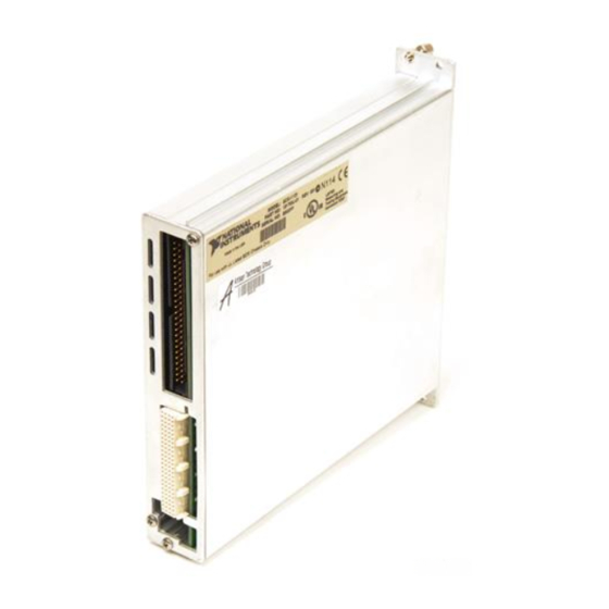
National Instruments SCXI-1121 User Manual (146 pages)
Four-Channel Isolated Universal Transducer Module for Signal Conditioning
Brand: National Instruments
|
Category: Transducer
|
Size: 0 MB
Table of Contents
Advertisement

National Instruments SCXI-1121 User Manual (162 pages)
Four-Channel Isolated Universal Transducer Module for Signal Conditioning
Brand: National Instruments
|
Category: Network Hardware
|
Size: 2 MB
Table of Contents
National Instruments SCXI-1121 Getting Started (158 pages)
Brand: National Instruments
|
Category: Control Unit
|
Size: 1 MB
Table of Contents
Advertisement
National Instruments SCXI-1121 User Manual (159 pages)
Brand: National Instruments
|
Category: Terminal Block
|
Size: 4 MB
Table of Contents
National Instruments SCXI-1121 Quick Start Manual (61 pages)
Signal Conditioning eXtensions for Instrumentation
Brand: National Instruments
|
Category: Control Unit
|
Size: 4 MB
Table of Contents

National Instruments SCXI-1121 Calibration Procedure (21 pages)
Brand: National Instruments
|
Category: I/O Systems
|
Size: 1 MB
Table of Contents
National Instruments SCXI-1121 User Manual (19 pages)
Brand: National Instruments
|
Category: Test Equipment
|
Size: 0 MB
Table of Contents
National Instruments SCXI-1121 Quick Start Manual (25 pages)
Signal Conditioning eXtensions for Instrumentation
Brand: National Instruments
|
Category: Test Equipment
|
Size: 2 MB
Table of Contents

National Instruments SCXI-1121 Calibration Procedure (21 pages)
Brand: National Instruments
|
Category: I/O Systems
|
Size: 0 MB
Table of Contents

National Instruments SCXI-1121 Calibration Procedure (16 pages)
Brand: National Instruments
|
Category: I/O Systems
|
Size: 0 MB
Table of Contents

National Instruments SCXI-1121 Instructions For Safe Use (4 pages)
Brand: National Instruments
|
Category: Computer Hardware
|
Size: 0 MB
Advertisement
Related Products
- National Instruments SCXI-1120
- National Instruments DAQ SCXI-1161
- National Instruments SCXI-1163
- National Instruments SCB-68
- National Instruments SC-2040
- National Instruments Module SCXI-1125
- National Instruments SCXI -1122
- National Instruments SCXI-1124
- National Instruments 6023E
- National Instruments 6024E