National Instruments SCXI-1000 Getting Started
Hide thumbs
Also See for SCXI-1000:
- Quick start manual (143 pages) ,
- User manual (43 pages) ,
- User manual (73 pages)

Related Manuals for National Instruments SCXI-1000


Summary of Contents for National Instruments SCXI-1000
- Page 1 SCXI ™ Getting Started with SCXI Getting Started with SCXI July 2000 Edition Part Number 320515F-01...
- Page 2 Sweden 08 587 895 00, Switzerland 056 200 51 51, Taiwan 02 2528 7227, United Kingdom 01635 523545 For further support information, see the Technical Support Resources appendix. To comment on the documentation, send e-mail to techpubs@ni.com © Copyright 1993, 2000 National Instruments Corporation. All rights reserved.
- Page 3 Any action against National Instruments must be brought within one year after the cause of action accrues. National Instruments shall not be liable for any delay in performance due to causes beyond its reasonable control.
-
Page 4: Table Of Contents
Installing Your SCXI Modules ..................2-2 Connecting the SCXI System to the DAQ Device or Computer ........2-2 Using the Parallel Port..................2-2 Using a Plug-in DAQ Device or DAQCard ............2-2 Using an RS-232 or RS-485 Serial Port ............2-6 © National Instruments Corporation Getting Started with SCXI... - Page 5 Contents Chapter 3 Configuring Your SCXI Hardware and Software Module Configuration ....................3-1 Analog Modules ......................3-2 Ground-Referenced and Floating Signal Sources ........... 3-3 SCXI-1100 Module..................3-4 SCXI-1102/B/C Module ................. 3-7 SCXI-1104/C Module ..................3-8 SCXI-1112 Module..................3-8 SCXI-1120/D Module..................3-8 SCXI-1121 Module..................
- Page 6 Baud Rate and Address Configuration..........3-57 SCXI Chassis .........................3-58 SCXI-2000 Chassis with Serial Communications...........3-58 Baud Rate and Address Configuration..........3-58 SCXI-1000, SCXI-1000DC, and SCXI-1001 Chassis ........3-58 Configure Your Software for Use with SCXI Products ..........3-59 Example Programs..................3-59 Chapter 4 Connecting and Using Accessories and Transducers Connecting Signal Wires to the SCXI System ..............4-1...
- Page 7 Contents Appendix A SCXI Troubleshooting and Common Questions Appendix B Technical Support Resources Glossary Index Figures Figure 1-1. SCXI Systems ..................1-2 Figure 1-2. SCXI System Components ..............1-4 Figure 1-3. SCXI Chassis Signal Routing ............... 1-5 Figure 1-4. Terminal Block Options................ 1-8 Figure 1-5.
- Page 8 Jumper Configuration................3-17 Table 3-12. SCXI-1121 Excitation Mode Jumper Configuration......3-18 Table 3-13. SCXI-1121 Excitation Level Jumper Configuration......3-20 Table 3-14. SCXI-1121 Maximum Load per Excitation Channel......3-21 Table 3-15. SCXI-1121 Half-Bridge Completion Network Jumper Configuration................3-22 © National Instruments Corporation Getting Started with SCXI...
- Page 9 Contents Table 3-16. SCXI-1121 Amplifier Output Referencing Jumper Configuration ................3-23 Table 3-17. SCXI-1122 Digital Signal Jumper Configurations ....... 3-24 Table 3-18. SCXI-1122 Analog Jumper Configuration ........... 3-25 Table 3-19. SCXI-1124 Chassis Jumper Configuration........... 3-27 Table 3-20. SCXI-1124 Device-Type Jumper Configuration ........3-28 Table 3-21.
-
Page 10: About This Manual
About This Manual This guide is a beginner’s handbook to the installation, configuration, and use of the National Instruments Signal Conditioning eXtensions for Instrumentation (SCXI) chassis, modules, and associated data acquisition (DAQ) devices. This guide is an introduction to SCXI, not a complete reference. - Page 11 SCXI-1126, SCXI-1140, SCXI-1141, SCXI-1142, SCXI-1143, SCXI-1520, SCXI-1530/1531, and SCXI-1540. SCXI analog output Refers to the SCXI-1124. module SCXI chassis Refers to the SCXI-1000, SCXI-1000DC, SCXI-1001, and SCXI-2000. SCXI communication Refers to the SCXI-2400. module SCXI digital module Refers to the SCXI-1160, SCXI-1161, SCXI-1162, SCXI-1162HV, SCXI-1163, and SCXI-1163R.
-
Page 12: Related Documentation
• Your SCXI chassis, module, terminal block, connector-and-shell, and cable assembly user manuals or installation guides • Your DAQ hardware user manual • Your National Instruments software manuals • Application notes © National Instruments Corporation xiii Getting Started with SCXI... -
Page 13: Introduction To Scxi
RS-232 or RS-485 serial connection. If you use an RS-485, you can connect multiple SCXI chassis within a single network. If you use an SCXI chassis without any analog input modules, you do not need an SCXI-1200 module in that chassis. © National Instruments Corporation Getting Started with SCXI... -
Page 14: Figure 1-1. Scxi Systems
Chapter 1 Introduction to SCXI PC Plug-In DAQ Device Conditioned Signals SCXI Signal X I- Conditioning Chassis and Modules a. Front-End Signal Conditioning for Plug-In DAQ Device Parallel Port Link SCXI Signal Conditioning and DAQ Modules X I- SCXI-1200 12-Bit DAQ Module b. -
Page 15: What You Need To Get Started
DAQ devices, and software, as shown in Figure 1-2. The following sections briefly describe the components of an SCXI system and help you to understand how they work together. © National Instruments Corporation Getting Started with SCXI... -
Page 16: Scxi Chassis
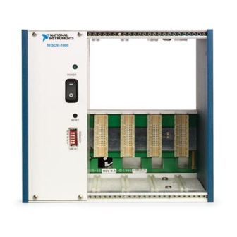
Terminal Block Extension (TBX) Terminal Block Extension (TBX) Figure 1-2. SCXI System Components SCXI Chassis The SCXI chassis houses the SCXI modules, supplying power and controlling the SCXIbus. National Instruments offers four SCXI chassis: • SCXI-1000 4-slot chassis • SCXI-1000DC 4-slot, DC-powered chassis •... -
Page 17: Scxi Modules
Transducers Figure 1-3. SCXI Chassis Signal Routing SCXI Modules National Instruments manufactures a variety of SCXI modules for use in SCXI chassis. Various analog input modules can multiplex, amplify, filter, and isolate voltage and current signals. Some modules have excitation potentials or currents and half-bridge completion networks for transducers such as strain gauges or resistive temperature devices (RTDs). -
Page 18: Table 1-1. Scxi Modules
Chapter 1 Introduction to SCXI Table 1-1 lists the National Instruments SCXI modules and accessories. For further descriptions of National Instruments SCXI modules, refer to Chapter 3, Configuring Your SCXI Hardware and Software. Table 1-1. SCXI Modules Product Classification Description... -
Page 19: Scxi Terminal Blocks
Several terminal blocks have a temperature sensor for cold-junction compensation with thermocouples. Terminal blocks can also perform additional signal conditioning function, including high-voltage attenuation, AC/DC coupling, bridge offset nulling, and shunt calibration. © National Instruments Corporation Getting Started with SCXI... -
Page 20: Figure 1-4. Terminal Block Options
Chapter 1 Introduction to SCXI Direct-Mount SCXI Terminal Block SCXI Chassis a. SCXI Direct-Mount Terminal Block TBX Terminal Block Shielded Cable SCXI Chassis b. TBX Terminal Block Figure 1-4. Terminal Block Options Getting Started with SCXI www.ni.com... -
Page 21: Table 1-2. Direct-Mount Terminal Blocks
— SCXI-1126 SCXI-1305 Terminal block AC/DC coupling, signal referencing, switch-configurable per channel, BNC connectors SCXI-1320 Terminal block — SCXI-1327 Terminal block 100:1 attenuation of voltages to 250 V switch configurable per channel © National Instruments Corporation Getting Started with SCXI... - Page 22 Chapter 1 Introduction to SCXI Table 1-2. Direct-Mount Terminal Blocks (Continued) Terminal/ Connector Terminal Block or Module Block Connector and Shell Sensor Other Features SCXI-1140 SCXI-1301 Terminal block — SCXI-1304 Terminal block AC/DC coupling, switch configurable per channel SCXI-1305 Terminal block AC/DC coupling signal referencing, switch-configurable per channel, BNC connectors...
- Page 23 Serial communication module The SCXI-1303, SCXI-1322, SCXI-1327, and SCXI-1328 use an onboard thermistor for sensing cold-junction temperature. Other terminal blocks use an IC temperature sensor. 300V when used with the SCXI-1125 © National Instruments Corporation 1-11 Getting Started with SCXI...
- Page 24 Chapter 1 Introduction to SCXI Getting Started with SCXI 1-12 www.ni.com...
-
Page 25: Connector-And-Shell Assemblies
The SCXI-1200 connects to the computer parallel port, or to the SCXI-2000 chassis or SCXI-2400 module, which in turn communicates with the computer using a serial port. © National Instruments Corporation 1-13 Getting Started with SCXI... -
Page 26: Scxi Cable Assemblies
SCXI-1350, chassis are daisy-chained using multichassis adapters with shielded or unshielded cables to a single plug-in DAQ device. You can control up to eight SCXI-1000, SCXI-1000DC, or SCXI-1001 chassis with a single AI, MIO, or DIO-24 device. Figure 1-5 shows a multichassis configuration using the SCXI-1346 multichassis adapter. -
Page 27: Optional Software
SCXI system using NI-DAQ driver software, LabWindows/CVI, LabVIEW for Windows, LabVIEW for Macintosh, or ComponentWorks. NI-DAQ driver software ships with your National Instruments DAQ device, SCXI-1200, SCXI-2000, or SCXI-2400. NI-DAQ has a library of functions that you can call from your application development environment (ADE). -
Page 28: Figure 1-6. The Relationship Between The Programming Environment
Chapter 1 Introduction to SCXI ComponentWorks is a collection of object linking and embedding (OLE) controls and dynamic link libraries (DLLs) for acquiring, analyzing, and presenting data within Visual Basic. Whether you are using conventional programming languages, LabVIEW, LabWindows/CVI, or ComponentWorks, your application uses the NI-DAQ driver software, as illustrated in Figure 1-6. -
Page 29: Overview Of Scxi Operation
The DAQ device then reads channel 0, as shown in Figure 1-7. NI-DAQ automatically performs this low-level digital communication and signal routing when you call the single-channel analog input functions. © National Instruments Corporation 1-17 Getting Started with SCXI... -
Page 30: Figure 1-7. Scxi Signal Routing
Chapter 1 Introduction to SCXI SCXI Chassis Module n Plug-In DAQ Device Input Channel 0 Multiplexing Conditioning DIO Lines Circuitry (program the chassis and modules) Analog Input Signals Module 1 Analog Bus Multiplexing Conditioning Circuitry Slot 0 Figure 1-7. SCXI Signal Routing With multichannel scanning, the DAQ device programs SCXI Slot 0 with a list of modules and the number of channels to scan from each module. -
Page 31: Analog And Digital Output Modules
The SCXI-1124 is a 6-channel isolated analog output module. As with the digital I/O modules, the SCXI-1124 is programmed serially by the DAQ device using a maximum of four digital output lines and one digital input line. © National Instruments Corporation 1-19 Getting Started with SCXI... -
Page 32: Installing Scxi Modules And Connecting The Scxi System
If you already have installed Measurement & Automation Explorer and the driver software and you received a newer NI-DAQ version, install the newer version now. © National Instruments Corporation Getting Started with SCXI... -
Page 33: Installing Your Daq Device
Chapter 2 Installing SCXI Modules and Connecting the SCXI System to the DAQ Device Installing Your DAQ Device If you are using SCXI with a plug-in DAQ device or DAQCard, install your DAQ hardware into your computer now and configure your DAQ device with Measurement &... - Page 34 DIO device. If the system contains any analog modules configured for parallel mode, connect each of these modules to a separate analog DAQ device. © National Instruments Corporation Getting Started with SCXI...
-
Page 35: Figure 2-1. Attaching The Scxi Cable Assembly To The Scxi Module And Chassis
Chapter 2 Installing SCXI Modules and Connecting the SCXI System to the DAQ Device Connect the connector at the bracket end of the SCXI cable assembly to the rear signal connector of the module. Figure 2-1 shows the cable assembly attached to the SCXI module and chassis. Female Connector to Module (Rear panel omitted for clarity) - Page 36 If you want to use more than 12 modules with a single DAQ device, you must use more than one SCXI chassis. In this case, you must use multichassis adapters. © National Instruments Corporation Getting Started with SCXI...
-
Page 37: Using An Rs-232 Or Rs-485 Serial Port
Chapter 2 Installing SCXI Modules and Connecting the SCXI System to the DAQ Device Using an RS-232 or RS-485 Serial Port You can use the RS-232 port on your computer to control one chassis up to 100 ft from your computer. If your chassis is farther away or you are using multiple chassis, you must use RS-485. -
Page 38: Configuring Your Scxi Hardware And Software
Figure 3-1. Rear of Module Grounding Screw Figure 3-1. Removing the SCXI Module Grounding Screw © National Instruments Corporation Getting Started with SCXI... -
Page 39: Analog Modules
Chapter 3 Configuring Your SCXI Hardware and Software Use this procedure to access the user-configurable jumpers. Remove the grounding screw shown in Figure 3-1. Remove the cover by inserting a flathead screwdriver in the slot at the bottom of the module and gently pushing the screwdriver down until the cover pops off, as shown in Figure 3-2. -
Page 40: Ground-Referenced And Floating Signal Sources
DAQ device is as follows: • E Series AI and MIO devices default to differential (DIFF) mode. National Instruments recommends that you leave your AI or MIO device configured for DIFF inputs. • The Lab/1200 devices default to referenced single-ended (RSE) mode. -
Page 41: Scxi-1100 Module
Caution If you plan to use any floating thermocouples or other floating-source transducers, National Instruments recommends that you leave jumper W1 in the factory-default setting and either ground the negative lead of each transducer to the chassis ground on your terminal block, or reference the transducer to ground at the source. In either case, the transducer must not have a high common-mode voltage. -
Page 42: Table 3-1. Scxi-1100 Input Signal Referencing Jumper Configurations
10 kHz and 4 Hz, positioned after the amplifier. You select filtering by setting a single jumper to one of three positions—W2, W3, or W4. Table 3-2 shows the SCXI-1100 filtering jumper configuration. © National Instruments Corporation Getting Started with SCXI... -
Page 43: Table 3-2. Scxi-1100 Filtering Jumper Configuration
Chapter 3 Configuring Your SCXI Hardware and Software Table 3-2. SCXI-1100 Filtering Jumper Configuration Jumper Description Configuration W2—Full bandwidth; no filtering W2 W3 W4 (factory-default position). W2 W3 W4 W3—10 kHz lowpass filter; maximum aggregate sampling rate is 6.7 kS/s. W2 W3 W4 W4—4 Hz lowpass filter;... -
Page 44: Scxi-1102/B/C Module
AB-R2—Select this position for AI or MIO devices in NRSE mode. Add current-loop receivers, if necessary. Process-current resistor packs are available from National Instruments. Refer to Input Filtering and Current-Loop Receivers in the SCXI-1100 User Manual for detailed information about filter pads and current loop receivers. -
Page 45: Scxi-1104/C Module
Chapter 3 Configuring Your SCXI Hardware and Software SCXI-1104/C Module ♦ SCXI-1104 This module is for signal conditioning of low voltage and medium voltage signals. The SCXI-1104 has 32 differential analog input channels. On each channel, the SCXI-1104 has a three-pole lowpass filter with a 2 Hz cutoff frequency to reject 60 Hz noise. -
Page 46: Table 3-4. Gain Jumper Allocation
1, 2, 5, 10, and 20. Tables 3-4 and 3-5 show how to set up the gain for each channel. Table 3-4. Gain Jumper Allocation Input Channel First Gain Second Gain Number Jumper Jumper © National Instruments Corporation Getting Started with SCXI... -
Page 47: Table 3-5. Gain Jumper Positions
Chapter 3 Configuring Your SCXI Hardware and Software Table 3-4. Gain Jumper Allocation (Continued) Input Channel First Gain Second Gain Number Jumper Jumper The SCXI-1120D has an additional fixed pre-stage gain of 0.5. The SCXI-1120 is shipped with the first-stage gain set to 100 (position A), and a second-stage gain set to 10 (position D). -
Page 48: Table 3-6. Scxi-1120 Filter Jumper Allocation
Table 3-6. SCXI-1120 Filter Jumper Allocation First Second Filter Jumper Filter Jumper Input 4 Hz 4 Hz Channel (Factory (Factory Number Default) 10 kHz Default) 10 kHz W17-A W17-B W18-A W18-B W19-A W19-B W20-A W20-B © National Instruments Corporation 3-11 Getting Started with SCXI... -
Page 49: Table 3-7. Scxi-1120D Filter Jumper Allocation
Chapter 3 Configuring Your SCXI Hardware and Software Table 3-6. SCXI-1120 Filter Jumper Allocation (Continued) First Second Filter Jumper Filter Jumper Input 4 Hz 4 Hz Channel (Factory (Factory Number Default) 10 kHz Default) 10 kHz W21-A W21-B W22-A W22-B W23-A W23-B W24-A... - Page 50 Use jumper W46 to configure the various referencing modes of the SCXI-1120/D instrumentation amplifier output. The correct output referencing mode depends on the input mode of the DAQ device you use. © National Instruments Corporation 3-13 Getting Started with SCXI...
-
Page 51: Scxi-1121 Module
Chapter 3 Configuring Your SCXI Hardware and Software Table 3-8 shows the signal referencing configurations for jumper W46. Table 3-8. SCXI-1120/D Signal Referencing Jumper Configuration Jumper Description Configuration B-R0R1—Parking position. Use this position for MIO or AI devices in DIFF input mode. (factory-default position). - Page 52 Use jumpers W3, W19, W29, and W41 to configure the first-stage gain of channels 0 through 3, respectively. Each jumper has four possible positions—A, B, C, and D—each corresponding to a particular gain. © National Instruments Corporation 3-15 Getting Started with SCXI...
-
Page 53: Table 3-9. Scxi-1121 First-Stage And Second-Stage Gain
Chapter 3 Configuring Your SCXI Hardware and Software Configure the second-stage gain. Use jumpers W4, W20, W30, and W42 to configure the second-stage gain of channels 0 through 3, respectively. Each of these jumpers has five possible positions—A, B, C, D, and E—each corresponding to a particular gain. -
Page 54: Table 3-11. Scxi-1121 First-Stage And Second-Stage Filter
W15, W22, W23, W34, W35, W46, and W47. Table 3-12 summarizes the excitation mode jumper settings. Notice that only position 1 is marked on the SCXI-1121 module. The factory-default excitation mode for each channel is voltage. © National Instruments Corporation 3-17 Getting Started with SCXI... -
Page 55: Table 3-12. Scxi-1121 Excitation Mode Jumper Configuration
Chapter 3 Configuring Your SCXI Hardware and Software Table 3-12. SCXI-1121 Excitation Mode Jumper Configuration Excitation Voltage Mode Jumpers Channel (Factory-Default Position) Current Mode Getting Started with SCXI 3-18 www.ni.com... - Page 56 0.450 mA. Refer to the transducer specifications to determine the necessary excitation level. See Table 3-13 for the SCXI-1121 excitation level jumper settings, and refer to Table 3-14 for the maximum load per excitation channel. © National Instruments Corporation 3-19 Getting Started with SCXI...
-
Page 57: Table 3-13. Scxi-1121 Excitation Level Jumper Configuration
Chapter 3 Configuring Your SCXI Hardware and Software Table 3-13. SCXI-1121 Excitation Level Jumper Configuration Excitation 3.333 V or 0.150 mA Jumpers Channel (Factory-Default Position) 10 V or 0.450 mA Getting Started with SCXI 3-20 www.ni.com... -
Page 58: Table 3-14. Scxi-1121 Maximum Load Per Excitation Channel
See Table 3-15 for half-bridge completion network jumper information, and refer to Figures 4-5, 4-6, and 4-7 for diagrams of standard bridge configurations. © National Instruments Corporation 3-21 Getting Started with SCXI... -
Page 59: Table 3-15. Scxi-1121 Half-Bridge Completion Network Jumper Configuration
Chapter 3 Configuring Your SCXI Hardware and Software Table 3-15. SCXI-1121 Half-Bridge Completion Network Jumper Configuration Disable Network Jumpers Channel Enable Network (Factory-Default Position) Getting Started with SCXI 3-22 www.ni.com... -
Page 60: Scxi-1122 Module
SCXI-1122 can operate in two modes. Use the two-wire scan mode with all 16 input channels used for input or the four-wire scan mode with the eight upper channels configured as sense leads for connecting input channels and © National Instruments Corporation 3-23 Getting Started with SCXI... - Page 61 Chapter 3 Configuring Your SCXI Hardware and Software the lower eight channels configured as current output channels. Other major features of this module include software-programmable gain and filtering, and the ability to account for voltage drop of long lead wires in strain-gauge measurement.
-
Page 62: Current-Loop Receivers
Current-Loop Receivers The SCXI-1122 includes provision for measuring current rather than voltage. National Instruments offers an SCXI process-current resistor pack, which consists of four 249 Ω, 0.1%, 5 ppm, 1/4 W resistors. For more information on how to install current loop receiver resistors, consult your SCXI-1122 User Manual. -
Page 63: Scxi-1124 Module
SCXI-1124 outputs are designed to generate DC or slowly-varying current or voltage signals, not waveforms. The SCXI-1124 works with National Instruments AI and MIO devices, Lab and 1200 devices, and DIO devices. You can control several SCXI-1124s in a single chassis with one DAQ device and in combination with other SCXI module types. - Page 64 If you are cabling this module directly to a DAQ device, set jumpers W1, W2, and W3 depending on the type of DAQ device you are using, as shown in Table 3-20. © National Instruments Corporation 3-27 Getting Started with SCXI...
-
Page 65: Scxi-1125 Module
Chapter 3 Configuring Your SCXI Hardware and Software Table 3-20. SCXI-1124 Device-Type Jumper Configuration Jumper Description Configuration D—Use this setting for all three jumpers if you want to connect the SCXI-1124 to a DIO device (factory-default position). W3 W4 M—Use this setting for all three jumpers if you want to connect the SCXI-1124 to an MIO or Lab/1200 device. -
Page 66: Scxi-1126 Module
DIFF mode measuring ground-referenced signal sources—each module channel is configured for a gain of 1. If this configuration is suitable for your application, do not adjust any of the jumpers or DIP switches. © National Instruments Corporation 3-29 Getting Started with SCXI... - Page 67 Chapter 3 Configuring Your SCXI Hardware and Software However, you must adjust the configuration if any of the following conditions is true: • Your input signals are floating or nonreferenced. • You are cabling this SCXI-1140 directly to a DAQ device and you are using a Lab/1200 device, or you are using an MIO or AI device in SE mode.
- Page 68 DIP switch to the on (closed) position as indicated in Table 3-24. Table 3-23. SCXI-1140 Gain Switches for Each Channel Channel Use DIP Switch © National Instruments Corporation 3-31 Getting Started with SCXI...
-
Page 69: Scxi-1141, Scxi-1142, And Scxi-1143 Modules
Chapter 3 Configuring Your SCXI Hardware and Software Table 3-23. SCXI-1140 Gain Switches for Each Channel (Continued) Channel Use DIP Switch Table 3-24. SCXI-1140 Switch Settings for Gain Selection Switch Desired Gain Closed Switches None A B C D Switch is shown in factory-default (gain = 1) position. If you are using any digital SCXI modules in serial mode and will connect the SCXI-1140 module to the DAQ device, configure the SCXI-1140 module to connect the MISO signal to the SERDATOUT... - Page 70 Pullup—Use this position for a cabled module in a single-chassis system or the first chassis in a multichassis system (factory-default position). No Pullup—Use this position for cabled modules in additional chassis in a multichassis system. © National Instruments Corporation 3-33 Getting Started with SCXI...
-
Page 71: Scxi-1520 Module
Chapter 3 Configuring Your SCXI Hardware and Software Table 3-26. SCXI-1141/1142/1143 Grounding and Shielding Jumper Configuration Jumper Description Configuration Parking position. Use this setting with DAQ devices in DIFF mode (factory-default position). R2 R1 R0 Use this position for DAQ devices with SE inputs, such as the Lab and 1200 devices, DAQCard-700, or MIO and AI devices in RSE mode. -
Page 72: Scxi-1530/1531 Module
Bessel filter to 2.5, 5, 10, or 20 kHz. You can set the gain to 1, 10, or 100X. All channels are simultaneously sampled and held to preserve timing and phase information. Excitation, bandwidth, and gain are set © National Instruments Corporation 3-35 Getting Started with SCXI... -
Page 73: Scxi-1540 Module
SCXI-1540 using Measurement & Automation Explorer or through function calls to NI-DAQ. Digital SCXI Modules In addition to analog SCXI modules, National Instruments produces a variety of digital modules—the SCXI-1160, SCXI-1161, SCXI-1162, SCXI-1162HV, SCXI-1163, and SCXI-1163R. You can connect these modules to either an analog or a digital DAQ device. -
Page 74: Communication Modes
SCXI module to the PC-DIO-24-equivalent half of the cable and use the MIO-16D as a digital device. If you use the DIO-24-equivalent half of the cable, you must select the parallel (secondary) operating mode in Measurement & Automation Explorer. © National Instruments Corporation 3-37 Getting Started with SCXI... -
Page 75: Scxi-1160 Module
Chapter 3 Configuring Your SCXI Hardware and Software SCXI-1160 Module This module controls 16 isolated SPDT relays. The module has three user-configurable jumpers for configuring the type of DAQ device connected to your module. Leave all other jumpers in the factory-default positions. -
Page 76: Scxi-1162 Module
You need to adjust jumpers on this module only if you connect the module directly to an analog DAQ device or use the module in parallel mode. If either of these conditions applies to you, read the rest of this section. © National Instruments Corporation 3-39 Getting Started with SCXI... - Page 77 Chapter 3 Configuring Your SCXI Hardware and Software Use the following procedure to configure your SCXI-1162 module: Select parallel or serial mode. Use jumper W2 to select whether the module transfers data in parallel to a digital DAQ device (or the DIO-24 connector of an MIO-16D device) or serially to either a digital or an analog DAQ device.
- Page 78 MIO device or Lab/1200 device. If you are using the SCXI-1162 in parallel mode, set jumper W6 to the PAR position. If the module is not connected directly to a DAQ device, the positions of W3, W4, and W6 are irrelevant. © National Instruments Corporation 3-41 Getting Started with SCXI...
-
Page 79: Scxi-1162Hv Module
Chapter 3 Configuring Your SCXI Hardware and Software Table 3-32 shows the SCXI-1162 device-type jumper configurations. Table 3-32. SCXI-1162 Device-Type Jumper Configuration Jumper Description Configuration MIO—Use this setting to configure the rear connector for an AI or MIO device or Lab/1200 device in serial mode (factory-default position). - Page 80 DIO—Use this setting to configure the rear connector for a DIO device (factory-default position). MIO—Use this setting to configure the rear connector for an MIO device. Includes AI or MIO device or Lab/1200 device. © National Instruments Corporation 3-43 Getting Started with SCXI...
-
Page 81: Scxi-1163 Module
Chapter 3 Configuring Your SCXI Hardware and Software Table 3-33. SCXI-1162HV Jumper Configuration (Continued) Jumper Description Configuration Pullup—Use this setting for a single-chassis system or for the first chassis in a multichassis system. Connects a pullup resistor to the SERDATOUT line (factory-default position). - Page 82 DAQ device to which the module is connected. If you are using the module in parallel mode, it must be directly connected to a digital DAQ device or the DIO-24 connector of an MIO-16D. © National Instruments Corporation 3-45 Getting Started with SCXI...
- Page 83 Chapter 3 Configuring Your SCXI Hardware and Software Table 3-35 shows the SCXI-1163 mode jumper configurations. Table 3-35. SCXI-1163 Mode Jumper Configuration Jumper Description Configuration S—Use this setting to configure the module in serial mode (factory-default position). P—Use this setting to configure the rear connector for a DIO device in parallel mode.
-
Page 84: Scxi-1163R Module
You should change the jumper configuration from the factory-default settings only if you plan to connect the SCXI-1163R directly to an MIO and AI device, or if you plan to use the SCXI-1163R in parallel mode. © National Instruments Corporation 3-47 Getting Started with SCXI... - Page 85 Chapter 3 Configuring Your SCXI Hardware and Software Tables 3-36 and 3-37 show the SCXI-1163R jumper configurations. Table 3-36. SCXI-1163R Device-Type Jumper Configuration Configuration for Configuration for Jumper Description DIO Device MIO Device Configures rear connector. Factory-default position is for DIO devices. Configures rear connector.
- Page 86 A on only one of the SCXI-1163R modules that are connected to the DAQ device in a multichassis system. It does not matter which of the SCXI-1163R modules cabled to the DAQ device has the pullup connected. © National Instruments Corporation 3-49 Getting Started with SCXI...
-
Page 87: Scxi-1200 Module
Chapter 3 Configuring Your SCXI Hardware and Software SCXI-1200 Module The SCXI-1200 controls the operation of and digitizes the conditioned analog signals from other SCXI modules. The SCXI-1200 has eight analog input channels, which can be configured as eight SE or four DIFF; a 12-bit successive-approximation ADC;... -
Page 88: Module Configuration
Unipolar—0 to 10 V Analog Input Range Bipolar—±5 V (factory setting) Unipolar—0 to 10 V Analog Input Mode RSE (factory setting) NRSE DIFF Both the analog input and analog output circuits are software configurable. © National Instruments Corporation 3-51 Getting Started with SCXI... -
Page 89: Analog Output Configuration
Chapter 3 Configuring Your SCXI Hardware and Software Analog Output Configuration The SCXI-1200 has two channels of analog output voltage available at the front I/O connector. You can configure each analog output channel for either unipolar or bipolar output. A unipolar configuration has a range of 0 to 10 V at the analog output. - Page 90 SCXI-1200 User Manual. Notice that the signal return path is through the negative terminal of the amplifier and through channel 1, 3, 5, or 7, depending on which channel pair you select. © National Instruments Corporation 3-53 Getting Started with SCXI...
-
Page 91: Analog Input Polarity And Range Configuration
Chapter 3 Configuring Your SCXI Hardware and Software Analog Input Polarity and Range Configuration You can select the analog input on the SCXI-1200 for either a unipolar range (0 to 10 V) or a bipolar range (–5 to +5 V). The range and the coding scheme are both software-selectable. -
Page 92: Figure 3-4. Scxi-1200 Front Connector Pin Assignments
39 40 EXTUPDATE* OUTB0 41 42 GATB0 COUTB1 43 44 GATB1 CCLKB1 45 46 OUTB2 GATB2 47 48 CLKB2 +5 V 49 50 DGND Figure 3-4. SCXI-1200 Front Connector Pin Assignments © National Instruments Corporation 3-55 Getting Started with SCXI... -
Page 93: Scxi-1180 Feedthrough Panel
SCXI-2400 Serial Communications Module The SCXI-2400 serial communications module adds RS-232 and RS-485 serial communications to any SCXI chassis, including the SCXI-1000, SCXI-1000DC, and SCXI-1001 chassis. You can either connect the SCXI-2400 module directly to the RS-232 serial COM port of a computer, or you can connect the SCXI-2400 module to an RS-485 network for long-distance, multidrop configurations. -
Page 94: Baud Rate And Address Configuration
See the SCXI-2400 User Manual for more information about changing the baud rate and address. Chassis Default Address = 1 Baud = 9600 bps Figure 3-5. SCXI-2400 Module Default Switch Settings © National Instruments Corporation 3-57 Getting Started with SCXI... -
Page 95: Scxi Chassis
Configuring Your SCXI Hardware and Software SCXI Chassis This section describes the SCXI-2000 chassis with serial communication and the SCXI-1000, SCXI-1000DC, and SCXI-1001 Chassis. SCXI-2000 Chassis with Serial Communications The SCXI-2000 is a four-slot chassis with built-in RS-232 and RS-485 serial communication. -
Page 96: Configure Your Software For Use With Scxi Products
Example Programs You can learn more about the SCXI system by running the example programs that are included with all National Instruments application software packages and with the NI-DAQ software you received with your DAQ device. Be sure to read the information in the remarks at the top of each example program and configure your SCXI system appropriately. -
Page 97: Connecting And Using Accessories And Transducers
Terminal/ Module Connector Cold-Junction Sensor Isothermal Others SCXI-1100 SCXI-1300 — SCXI-1102/B/C SCXI-1303 Signal referencing TBX-1303 and open thermocouple detection SCXI-1308 Current input SCXI-1310 Low-cost connector and shell SCXI-1104/C SCXI-1300, — TBX-96 — © National Instruments Corporation Getting Started with SCXI... - Page 98 Chapter 4 Connecting and Using Accessories and Transducers Table 4-1. SCXI Module and Connector Compatibility (Continued) Features Terminal/ Module Connector Cold-Junction Sensor Isothermal Others SCXI-1120/D SCXI-1320 SCXI-1125 SCXI-1327 100:1 attenuation of voltages to 250 V SCXI-1328 — TBX-1328 — SCXI-1330 Low-cost connector and shell SCXI-1338...
- Page 99 SCXI-1181, you must remove the keys by sliding the two coding wedges from their dovetail grooves. The SCXI-1181 is not intended for use with hazardous voltages (exceeding 42 V ). National Instruments is not liable for damages or injuries resulting from improper installation.
-
Page 100: Scxi-13Xx Terminal Blocks
Chapter 4 Connecting and Using Accessories and Transducers SCXI-13XX Terminal Blocks An SCXI-13XX terminal block contains a number of labeled screw terminals to which you can connect signal wires, along with a strain-relief mechanism to prevent the connections from being inadvertently loosened. The terminal block fastens directly to the front of the appropriate SCXI module. -
Page 101: Onboard Temperature Sensors For Cold-Junction Compensation
In LabVIEW, use the Convert Thermistor VI. In NI-DAQ, use the function call. Refer to Transducer Conversion Thermistor_Convert Functions in the NI-DAQ User Manual for PC Compatibles, for more information. © National Instruments Corporation Getting Started with SCXI... -
Page 102: Opening The Scxi-13Xx Terminal Block
Chapter 4 Connecting and Using Accessories and Transducers Opening the SCXI-13XX Terminal Block You open terminal blocks the same way that you open modules. Figure 4-2 shows the back of the terminal block. Grounding Screw Figure 4-2. Removing the Terminal Block Grounding Screw To open the terminal block, remove two cover screws as shown in Figure 4-3. -
Page 103: Connector-And-Shell Assemblies
Table 4-1, earlier in this chapter, summarizes the module compatibility for these connectors. Connecting Transducers to the SCXI System National Instruments application software packages include transducer conversion functions for thermocouples, strain gauges, and RTDs. The following sections explain how to connect these transducers to the SCXI system. -
Page 104: Using Thermocouples With The Scxi-1102
Chapter 4 Connecting and Using Accessories and Transducers You can also ground the thermocouple at the source, assuming the ground difference between the source and your SCXI system is within the common-mode voltage range of the SCXI module. If the thermocouple is already ground-referenced, do not connect the negative input to chassis ground. -
Page 105: Noise And Filtering
If the strain gauge has a high common-mode voltage, refer to Appendix A, Specifications, of the SCXI-1121 User Manual to verify that the common-mode voltage is within the specified limits before connecting the signal to the SCXI-1121. © National Instruments Corporation Getting Started with SCXI... -
Page 106: Figure 4-4. Connecting The Half-Bridge Strain Gauge To Channel 1 Of The
Connecting and Using Accessories and Transducers Failure to verify that the common-mode voltage is within specified limits can damage the SCXI system and is potentially dangerous. National Instruments is not liable for damages or injuries resulting from improper configuration. If you have a large common-mode voltage (>30 V... - Page 107 The following acronyms and symbols apply to Figures 4-5 through 4-7: ε strain GF = Gauge Factor ν Poisson's Ratio ) Strained – (V ) Unstrained] Line Resistance Gauge Resistance • Connection to Terminal Block © National Instruments Corporation 4-11 Getting Started with SCXI...
-
Page 108: Figure 4-5. Quarter-Bridge Configurations
Chapter 4 Connecting and Using Accessories and Transducers Quarter-Bridge Configuration I SCXI-1121 Module with Voltage Excitation and Half-Bridge Completion Network Enabled – – – CH– Dummy Resistor (User Installed) EX– –4 V • GF (1 + 2V Quarter-Bridge Configuration II SCXI-1121 Module with Voltage Excitation and Half-Bridge Completion... -
Page 109: Figure 4-6. Half-Bridge Configurations
– CH– EX– –4 V • Half-Bridge Configuration II SCXI-1121 Module with Voltage Excitation and Half-Bridge Completion Network Enabled – – – CH– EX– –2 V • Figure 4-6. Half-Bridge Configurations © National Instruments Corporation 4-13 Getting Started with SCXI... -
Page 110: Figure 4-7. Full-Bridge Configurations
Chapter 4 Connecting and Using Accessories and Transducers SCXI-1121 Module with Voltage Excitation – Enabled Strain Gauge Full-Bridge Configuration I – –V – EX– SCXI-1121 Module with Voltage Excitation Enabled – Strain Gauge Full-Bridge Configuration II – –2 V – EX–... - Page 111 Half-bridge completion is provided inside the SCXI-1520 module. You configure the module for half-bridge completion under software control. © National Instruments Corporation 4-15 Getting Started with SCXI...
-
Page 112: Figure 4-8. Scxi-1520 To Scxi-1314 Quarter-Bridge Connection
Chapter 4 Connecting and Using Accessories and Transducers Quarter-Bridge Configuration I Voltage Excitation and Half-Bridge Completion Network Enabled – – Quarter-Bridge Completion Resistor –4 V • GF (1 + 2V Quarter-Bridge Configuration II Voltage Excitation and Half-Bridge Completion Network Enabled –... -
Page 113: Figure 4-9. Scxi-1520 To Scxi-1314 Half-Bridge Connection
Network Enabled – – P– –4 V • Half-Bridge Configuration II Voltage Excitation and Half-Bridge Completion Network Enabled – – P– –2 V • Figure 4-9. SCXI-1520 to SCXI-1314 Half-Bridge Connection © National Instruments Corporation 4-17 Getting Started with SCXI... -
Page 114: Figure 4-10. Scxi-1520 To Scxi-1314 Full-Bridge Connection
Chapter 4 Connecting and Using Accessories and Transducers Voltage Excitation Enabled and S– Half-Bridge – Completion Network Disabled Full-Bridge Configuration I –V – P– Voltage Excitation Enabled and S– Half-Bridge – Completion Network Disabled Full-Bridge Configuration II –2 V – P–... -
Page 115: Rtds
Refer to Appendix A, Specifications, in the SCXI-1121 User Manual. Common-mode voltage that is not within the specified limits can damage the SCXI system and is potentially dangerous. National Instruments is not liable for damages or injuries from improper configuration. If you have a common-mode voltage greater than... - Page 116 Chapter 4 Connecting and Using Accessories and Transducers MODULE TYPE: 1121 1120 CH 0 CH 0 Red Wire EX 0 CH 1 Black Wire CH 1 CH 2 EX 1 CH 3 Red Wire CH 2 CH 4 Black Wire EX 2 CH 5 CH 3...
-
Page 117: Current Excitation
Two-Wire RTD Configuration • = Connection to Terminal Block Note: Four-wire RTDs produce more accurate temperature measurements than either two-wire or three-wire RTDs, which introduce lead resistance errors. Figure 4-12. SCXI-1121 RTD Configurations © National Instruments Corporation 4-21 Getting Started with SCXI... - Page 118 Warning Exceeding the overvoltage protection or isolation rating on the excitation output can damage the SCXI-1122, the SCXIbus, and the DAQ device. National Instruments is not liable for any damages or injuries resulting from such signal connections. Excitation Level Each excitation channel of the SCXI-1122 has one level: •...
-
Page 119: Analog Circuitry In The Scxi-1122
The analog circuitry consists of a relay multiplexer, a software-programmable gain isolation amplifier, software-programmable filtering, a temperature sensor channel for cold-junction compensation, calibration circuitry, and voltage and current excitation channel outputs. © National Instruments Corporation 4-23 Getting Started with SCXI... -
Page 120: Analog Input Channels
Chapter 4 Connecting and Using Accessories and Transducers Analog Input Channels A relay multiplexer routes input signals to the isolation amplifier. This relay multiplexer can be configured in two-wire or four-wire mode scanning. In the two-wire scan mode, all 16 channels operate as voltage sense channels. -
Page 121: Excitation Output Channels
The voltage excitation channel is primarily used to provide power to a strain gauge configured in a Wheatstone bridge. To verify correct bridge operation, you can use shunt calibration. © National Instruments Corporation 4-25 Getting Started with SCXI... - Page 122 Chapter 4 Connecting and Using Accessories and Transducers When you select shunt calibration during a Wheatstone bridge strain measurement, a 301 kΩ, 1% resistor internally shunts across the strain gauge between the VEX+ and the CH+ terminals. This resistor is socketed so you can change its value to meet your requirements.
- Page 123 Figure 4-14. Series Connection with Current Excitation CH+8 CH+0 CH–0 CH–8 CH+9 CH+1 CH–1 CH–9 CH+15 CH+7 CH–7 CH–15 Any R 5 k Figure 4-15. Four-Wire Scan Connection with Multiplexed Current Excitation © National Instruments Corporation 4-27 Getting Started with SCXI...
-
Page 124: Analog Output Channel Signal Connections On The Scxi-1124
Chapter 4 Connecting and Using Accessories and Transducers Note Always connect the current excitation terminals outside the sense terminals as shown in both Figures 4-14 and 4-15. Each approach has its advantages and disadvantages, as listed in Table 4-6. Table 4-6. Pros and Cons of Two-Wire and Four-Wire Connections with Current-Excited Transducers Type Pros Cons... - Page 125 0-20 mA 0-20 mA Load Load ISINK ISINK – High – – a. Floating Load b. Load with High Common-Mode Voltage Figure 4-17. DAC Channel Connection as Current Output, Internal Loop Supply © National Instruments Corporation 4-29 Getting Started with SCXI...
- Page 126 Chapter 4 Connecting and Using Accessories and Transducers Figure 4-18 shows how to connect a DAC channel as a current output using an external loop supply. Load – ISINK ISINK Load – 0-20 mA 0-20 mA a. Floating Load and Floating Supply Connection ISINK ISINK Load...
-
Page 127: Chassis Ground Connections
Use the strain-relief tab on the terminal block for the safety earth ground. LVDTs, RVDTs, and Resolvers LVDTs, RVDTs, and resolvers require signal conditioning with AC excitation and synchronous demodulation. The SCXI-1540 provides these specialized functions. © National Instruments Corporation 4-31 Getting Started with SCXI... -
Page 128: Connecting To Lvdts And Rvdts
Chapter 4 Connecting and Using Accessories and Transducers Connecting to LVDTs and RVDTs Figures 4-20 and 4-21 show the connections made to a 4-wire and 5-wire LVDT or RVDT using the SCXI-1540 with the SCXI-1315 terminal block. Figure 4-20 shows that you can connect a device with six wires using only four wires. -
Page 129: Synchronizing Channels
Synchronization prevents beat frequencies from appearing in the data. Beat frequencies are the result of channel oscillators running at slightly different frequencies and coupling into adjacent channels through crosstalk in the cable. © National Instruments Corporation 4-33 Getting Started with SCXI... - Page 130 Chapter 4 Connecting and Using Accessories and Transducers CH0+ CH0– Master Channel– SYNC0 Do NOT Configure for External Synchronization EX0+ EX0– CH1+ CH1– Slave Channel– SYNC1 Configure for External Synchronization EX1+ EX1– CH2+ CH2– SYNC2 Slave Channel– Configure for External Synchronization EX2+ EX2–...
-
Page 131: Connecting To Resolvers
CH0– cosine Slave Channel– SYNC0 stator Configure for External Synchronization EX0+ EX0– CH1+ CH1– Master Channel– SYNC1 Do NOT Configure for External Synchronization EX1+ EX1– Figure 4-23. Interfacing to a Resolver © National Instruments Corporation 4-35 Getting Started with SCXI... - Page 132 SCXI Troubleshooting and Common Questions This appendix contains troubleshooting tips and answers to questions that SCXI users commonly ask National Instruments technical support staff. Before you contact National Instruments, try the following troubleshooting tips. Troubleshooting Tips • Make sure you have the most recent version of the NI-DAQ driver software.
- Page 133 Appendix A SCXI Troubleshooting and Common Questions Common Questions and Problems All my channels float to a positive rail when I try to take a measurement. Make sure that the signal reference settings for your DAQ device match the SCXI module. For example, if your device is configured for NRSE, make sure that the cabled SCXI module is also (this may require a jumper setting).
- Page 134 Appendix A SCXI Troubleshooting and Common Questions My chassis worked fine until I inadvertently removed and reinserted a module while the chassis was on. Now my chassis does not turn on. What can I do? You may have blown a fuse. Consult the SCXI Chassis User Manual for more information on your fuses.
- Page 135 Appendix A SCXI Troubleshooting and Common Questions now using four MIO device scan list entries instead of just one. For more complicated gain distributions, your MIO device scan list will be longer. In LabVIEW, use the channel list strings and input limits arrays to specify your gain distribution.
- Page 136 Appendix A SCXI Troubleshooting and Common Questions My SCXI-1162 module cannot read serial data unless I connect it directly to my DAQ device. Also, my SCXI-1163 module seems to be reading faulty information from the status registers. What is causing these problems? The SCXI-1162 and SCXI-1163 send digital data to the SCXIbus.
- Page 137 Technical Support Resources Web Support National Instruments Web support is your first stop for help in solving installation, configuration, and application problems and questions. Online problem-solving and diagnostic resources include frequently asked questions, knowledge bases, product-specific troubleshooting wizards, manuals, drivers, software updates, and more. Web support is available through the Technical Support section of www.ni.com...
- Page 138 Appendix B Technical Support Resources Worldwide Support National Instruments has offices located around the world to help address your support needs. You can access our branch office Web sites from the Worldwide Offices section of . Branch office web sites www.ni.com...
- Page 139 A/D converter. An electronic device, often an integrated circuit, that converts an analog voltage to a digital number. © National Instruments Corporation Getting Started with SCXI...
- Page 140 Glossary ADC resolution the resolution of the ADC, which is measured in bits. An ADC with 16 bits has a higher resolution, and thus a higher degree of accuracy, than a 12-bit analog input ANSI American National Standards Institute AT E Series devices these AT devices have an E- toward the ends of their names, such as the AT-MIO-16DE-10 and AT-AI-16XE-10 bandwidth...
- Page 141 PCMCIA cards, and devices such as the DAQPad-1200, which connects to your computer parallel port, are all examples of DAQ devices. SCXI modules are distinct from devices, with the exception of the SCXI-1200, which is a hybrid. © National Instruments Corporation Getting Started with SCXI...
- Page 142 Glossary DIFF (differential) input an analog input consisting of two terminals, both of which are isolated from computer ground, whose difference is measured digital port port digital I/O DIO-24 refers to the PC-DIO-24, DAQCard-DIO-24, and PCI-6503 DIO-32 refers to the PCI-DIO-32HS, PCI-6533, or PXI-6533 DIO-96PnP refers to the PC-DIO-96PnP DIO device...
- Page 143 IEEE Institute of Electrical and Electronics Engineers interrupt a computer signal indicating that the CPU should suspend its current task to service a designated activity input/output interrupt request Industry Standard Architecture © National Instruments Corporation Getting Started with SCXI...
- Page 144 Glossary 1,000 samples Kword 1,024 words of memory Lab/1200 device refers to the DAQCard-1200, DAQPad-1200, Lab-PC+, Lab-PC-1200, Lab-PC-1200AI, PCI-1200, and SCXI-1200 light-emitting diode library A file containing compiled object modules, each comprised of one of more functions, that can be linked to other object modules that make use of these functions.
- Page 145 DAQ device to keep a continuous buffer filled with data, so that when the trigger conditions are met, the sample includes the data leading up to the trigger condition © National Instruments Corporation Getting Started with SCXI...
- Page 146 Glossary programmed I/O the standard method a CPU uses to access an I/O device—each byte of data is read or written by the CPU points PCI eXtensions for Instrumentation. PXI is an open specification that builds off the CompactPCI specification by adding instrumentation-specific features random-access memory resistance-capacitor...
- Page 147 Glossary RTSI real-time system integration (bus). The National Instruments timing bus that connects DAQ devices directly, by means of connectors on top of the devices, for precise synchronization of functions. RVDT rotary variable differential transformer. A transformer-based sensor used to measure absolute angular displacement.
- Page 148 Glossary SCXI DAQ module refers to the SCXI-1200 software development kit self-calibrating a property of a DAQ device that has an extremely stable onboard reference and calibrates its own A/D and D/A circuits without manual adjustments by the user serial mode the mode by which SCXI-116X modules communicate digital information serially rather than in parallel SE (single-ended)
- Page 149 Glossary volts volts direct current )strained – (V )unstrained volts, root mean square © National Instruments Corporation G-11 Getting Started with SCXI...
- Page 150 3-37 SCXI-1122, 3-23 serial mode, 3-37 SCXI-1124, 3-26 ComponentWorks software, 1-16 SCXI-1125, 3-28 configuration SCXI-1126, 3-29 analog modules, 3-2 SCXI-1140, 3-29 floating signal sources, 3-3 SCXI-1141, 3-32 ground-referenced signal source, 3-3 © National Instruments Corporation Getting Started with SCXI...
- Page 151 (figure), SCXI-1162, 3-39 SCXI-1162HV, 3-42 removing module cover (figure), 3-2 SCXI-1163, 3-44 problems, A-2 SCXI-1163R, 3-47 SCXI-1000, SCXI-1000DC, and SCXI-1200, 3-50 SCXI-1001 chassis, 3-58 SCXI-2400, 3-56 SCXI-2000 chassis with serial communications, 3-58 overview, 1-19 software configuration, 3-59...
- Page 152 4-9 mode noise filtering for thermocouples, 4-9 SCXI-1140 module, 3-30 RTD analog input channels, 4-25 isolation amplifier for RTDs, 4-25 floating signal sources, 3-3 fuse blown, A-3 jumper settings © National Instruments Corporation Getting Started with SCXI...
- Page 153 A-1 1-14 multiplexed mode of operation, 1-17 referenced single-ended (RSE) mode description, 3-53 National Instruments Web support, B-1 Lab devices, 3-3 NI Developer Zone, B-1 SCXI-1200 configuration (table), 3-52 NI-DAQ driver software, 1-15 relay multiplexer for RTDs, 4-24...
- Page 154 4-31 RSE mode. See referenced single-ended SCXI multichassis system with plug-in (RSE) mode. DAQ device, 1-14 RTDs, 4-19 SCXI-1000, SCXI-1000DC, and SCXI-1001 chassis, 3-58 analog circuitry, 4-23 SCXI-2000 chassis with serial analog input channels, 4-24 communications, 3-58 sense and current output channel...
- Page 155 Index configuring, 3-58 signal referencing jumper configuration (table), 3-14 SCXI-1001 chassis thermocouples, 4-8 configuring, 3-58 SCXI-1121 module SCXI-1100 module configuration and jumper settings, 3-14 configuration and jumper settings, 3-4 connecting MISO signal to filtering, 3-5 SERDATOUT pin, 3-23 input signal referencing mode, 3-4 enabling half-bridge completion PGIA output referencing modes, 3-6 network, 3-21...
- Page 156 3-51 3-32 overview, 3-50 SCXI-1160 module configuration and jumper parallel port interface, 3-50 settings, 3-38 SCXI-1320 terminal block (figure), 4-20 SCXI-1161 module configuration and jumper SCXI-1321 terminal block (figure), 4-10 settings, 3-38 © National Instruments Corporation Getting Started with SCXI...
- Page 157 Index SCXI-1520 module connector-and-shell assemblies, 4-7 configuration, 3-34 SCXI module and connector compatibility (table), 4-1 NI-DAQ functions applicable to SCXI-1520 (table), 3-35 terminal blocks, 4-4 strain gauges, 4-15 onboard temperature sensors for cold-junction compensation, 4-5 excitation voltage ranges for configuration and gauge opening SCXI-13XX terminal block, resistances (table), 4-15 SCXI-2000 chassis with serial...
- Page 158 SCXI-1125 modules, 4-8 transducers, 4-7 chassis ground connections, 4-31 Web support, B-1 RTDs, 4-19 worldwide technical support, B-2 analog circuitry, 4-23 analog input channels, 4-24 analog output channel signal connections to SCXI-1124, 4-28 © National Instruments Corporation Getting Started with SCXI...
Need help?
Do you have a question about the SCXI-1000 and is the answer not in the manual?
Questions and answers