Sign In
Upload
Manuals
Brands
National Instruments Manuals
Network Hardware
6023E
National Instruments 6023E Manuals
Manuals and User Guides for National Instruments 6023E. We have
1
National Instruments 6023E manual available for free PDF download: User Manual
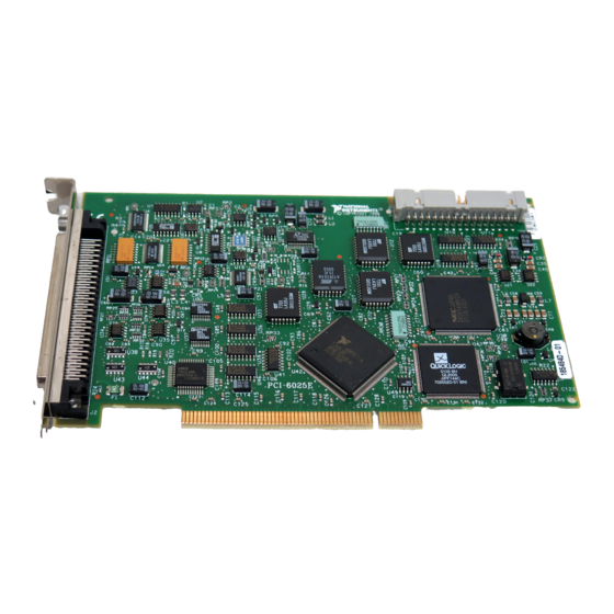
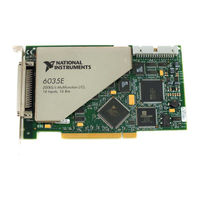
National Instruments 6023E User Manual (136 pages)
Multifunction I/O Devices for PCI, PXI, CompactPCI, and PCMCIA Bus Computers
Brand:
National Instruments
| Category:
Network Hardware
| Size: 1.04 MB
Table of Contents
User Manual
1
Important Information
3
Table of Contents
4
About this Manual
9
Conventions Used in this Manual
9
Related Documentation
10
Chapter 1 Introduction
11
Features of the 6023E, 6024E, and 6025E
11
Using PXI with Compactpci
12
What You Need to Get Started
12
Software Programming Choices
13
National Instruments Application Software
13
NI-DAQ Driver Software
14
Optional Equipment
15
Figure 1-1. the Relationship between the Programming Environment
15
NI-DAQ, and Your Hardware
15
Chapter 2 Installation and Configuration
17
Software Installation
17
Unpacking
17
Hardware Installation
18
Hardware Configuration
19
Chapter 3 Hardware Overview
20
Figure 3-1. PCI-6023E, PCI-6024E, PCI-6025E, and PXI-6025E Block Diagram
20
Analog Input
21
Figure 3-2. Daqcard-6024E Block Diagram
21
Input Mode
21
Input Range
22
Table 3-1. Available Input Configurations
22
Table 3-2. Measurement Precision
22
Dithering
23
Figure 3-3. Dithering
24
Multichannel Scanning Considerations
24
Analog Output
25
Analog Output Glitch
25
Digital I/O
26
Timing Signal Routing
26
Figure 3-4. CONVERT* Signal Routing
27
Programmable Function Inputs
27
Device and RTSI Clocks
28
RTSI Triggers
28
Figure 3-5. PCI RTSI Bus Signal Connection
29
Figure 3-6. PXI RTSI Bus Signal Connection
30
Table 3-3. Pins Used by PXI E Series Device
30
Chapter 4 Signal Connections
31
I/O Connector
31
Table 4-1. I/O Connector Details
31
Figure 4-1. I/O Connector Pin Assignment for the 6023E/6024E
32
Figure 4-2. I/O Connector Pin Assignment for the 6025E
33
Table 4-2. I/O Connector Signal Descriptions
34
Table 4-3. I/O Signal Summary
37
Analog Input Signal Overview
38
Types of Signal Sources
38
Floating Signal Sources
39
Ground-Referenced Signal Sources
39
Analog Input Modes
39
Figure 4-3. Programmable Gain Instrumentation Amplifier (PGIA)
40
Analog Input Signal Connections
41
Figure 4-4. Summary of Analog Input Connections
42
Differential Connection Considerations (DIFF Input Configuration)
43
Differential Connections for Ground-Referenced Signal Sources
44
Figure 4-5. Differential Input Connections for Ground-Referenced Signals
44
Differential Connections for Nonreferenced or Floating Signal Sources
45
Figure 4-6. Differential Input Connections for Nonreferenced Signals
45
Single-Ended Connection Considerations
47
Figure 4-7. Single-Ended Input Connections for Nonreferenced or Floating Signals
48
Single-Ended Connections for Floating Signal Sources (RSE Configuration)
48
Single-Ended Connections for Grounded Signal Sources (NRSE Configuration)
48
Common-Mode Signal Rejection Considerations
49
Analog Output Signal Connections
49
Figure 4-8. Single-Ended Input Connections for Ground-Referenced Signals
49
Digital I/O Signal Connections
50
All Devices
50
Figure 4-9. Analog Output Connections
50
Figure 4-10. Digital I/O Connections
51
Programmable Peripheral Interface (PPI)
52
Figure 4-11. Digital I/O Connections Block Diagram
52
Port C Pin Assignments
53
Table 4-4. Port C Signal Assignments
53
Power-Up State
54
Changing DIO Power-Up State to Pulled Low
54
Figure 4-12. DIO Channel Configured for High DIO Power-Up State with External Load
54
Table 4-5. Signal Names Used in Timing Diagrams
55
Timing Specifications
55
Figure 4-13. Timing Specifications for Mode 1 Input Transfer
57
Mode 1 Input Timing
57
Figure 4-14. Timing Specifications for Mode 1 Output Transfer
58
Mode 1 Output Timing
58
Figure 4-15. Timing Specifications for Mode 2 Bidirectional Transfer
59
Mode 2 Bidirectional Timing
59
Power Connections
60
Timing Connections
60
Programmable Function Input Connections
61
Figure 4-16. Timing I/O Connections
61
DAQ Timing Connections
62
Figure 4-17. Typical Posttriggered Acquisition
62
EXTSTROBE* Signal
63
Figure 4-18. Typical Pretriggered Acquisition
63
Figure 4-19. SCANCLK Signal Timing
63
SCANCLK Signal
63
Figure 4-20. EXTSTROBE* Signal Timing
64
Figure 4-21. TRIG1 Input Signal Timing
64
TRIG1 Signal
64
Figure 4-22. TRIG1 Output Signal Timing
65
TRIG2 Signal
65
Figure 4-23. TRIG2 Input Signal Timing
66
Figure 4-24. TRIG2 Output Signal Timing
66
STARTSCAN Signal
66
Figure 4-25. STARTSCAN Input Signal Timing
67
Figure 4-26. STARTSCAN Output Signal Timing
67
CONVERT* Signal
68
Figure 4-27. CONVERT* Input Signal Timing
68
AIGATE Signal
69
Figure 4-28. CONVERT* Output Signal Timing
69
Figure 4-29. SISOURCE Signal Timing
70
SISOURCE Signal
70
Waveform Generation Timing Connections
70
WFTRIG Signal
70
UPDATE* Signal
71
UISOURCE Signal
72
General-Purpose Timing Signal Connections
73
GPCTR0_SOURCE Signal
73
GPCTR0_GATE Signal
74
GPCTR1_GATE Signal
76
GPCTR1_SOURCE Signal
76
FREQ_OUT Signal
79
Field Wiring Considerations
79
Chapter 5 Calibration
80
Loading Calibration Constants
80
Self-Calibration
81
External Calibration
81
Other Considerations
82
Appendix A Specifications
83
Dynamic Characteristics
86
Output Characteristics
86
Power Requirement
91
Operating Environment
92
Storage Environment
92
Input Characteristics
93
Appendix B
101
Custom Cabling
101
Figure B-1. 68-Pin E Series Connector Pin Assignments
103
Figure B-2. 68-Pin Extended Digital Input Connector Pin Assignments
104
Figure B-3. 50-Pin E Series Connector Pin Assignments
105
Figure B-4. 50-Pin Extended Digital Input Connector Pin Assignments
106
General Information
107
Dithering
117
Programmable Gain Instrumentation Amplifier
122
Advertisement
Advertisement
Related Products
National Instruments USB device 622x
National Instruments USB device 625x
National Instruments USB device 628x
National Instruments 6024E
National Instruments 6025E
National Instruments 6008
National Instruments VXI/VMEpc 600 series
National Instruments 6035E
National Instruments 6034E
National Instruments 6534
National Instruments Categories
Control Unit
I/O Systems
Controller
Computer Hardware
Measuring Instruments
More National Instruments Manuals
Login
Sign In
OR
Sign in with Facebook
Sign in with Google
Upload manual
Upload from disk
Upload from URL