Sign In
Upload
Manuals
Brands
National Instruments Manuals
Network Hardware
SCXI-1163
National Instruments SCXI-1163 Manuals
Manuals and User Guides for National Instruments SCXI-1163. We have
2
National Instruments SCXI-1163 manuals available for free PDF download: Getting Started, User Manual
National Instruments SCXI-1163 Getting Started (158 pages)
Brand:
National Instruments
| Category:
Control Unit
| Size: 1.71 MB
Table of Contents
Table of Contents
4
About this Manual
10
Conventions Used in this Guide
10
Related Documentation
12
Chapter 1 Introduction to SCXI
13
Appendix A
14
Appendix B
14
Figure 1-1. SCXI Systems
14
What You Need to Get Started
15
Identifying Your SCXI Components
15
Figure 1-2. SCXI System Components
16
SCXI Chassis
16
Figure 1-3. SCXI Chassis Signal Routing
17
SCXI Modules
17
Table 1-1. SCXI Modules
18
SCXI Terminal Blocks
19
Figure 1-4. Terminal Block Options
20
Table 1-2. Direct-Mount Terminal Blocks
21
Connector-And-Shell Assemblies
25
DAQ Modules
25
DAQ Plug-In Devices and PC Cards
25
SCXI Cable Assemblies
26
SCXI Multichassis System with Plug-In DAQ Device
26
Table 1-4. SCXI Cable Assemblies
26
Figure 1-5. Multichassis SCXI System with Shielded Cabling
27
Optional Software
27
Figure 1-6. the Relationship between the Programming Environment
28
Overview of SCXI Operation
29
Analog Input Modules
29
Figure 1-7. SCXI Signal Routing
30
Analog and Digital Output Modules
31
Chapter 2
32
Installing SCXI Modules and Connecting the SCXI System
32
To the DAQ Device
32
Installing Your Software
32
Installing Your DAQ Device
33
Installing Your SCXI Modules
33
Connecting the SCXI System to the DAQ Device or Computer
33
Using the Parallel Port
33
Using a Plug-In DAQ Device or Daqcard
33
Figure 2-1. Attaching the SCXI Cable Assembly to the SCXI Module and Chassis
35
Using an RS-232 or RS-485 Serial Port
37
Chapter 3 Configuring Your SCXI Hardware and Software
38
Module Configuration
38
Figure 3-1. Removing the SCXI Module Grounding Screw
38
Analog Modules
39
Figure 3-2. Removing the SCXI Module Cover
39
Ground-Referenced and Floating Signal Sources
40
SCXI-1100 Module
41
Table 3-1. SCXI-1100 Input Signal Referencing Jumper Configurations
42
Table 3-2. SCXI-1100 Filtering Jumper Configuration
43
SCXI-1102/B/C Module
44
Table 3-3. SCXI-1100 PGIA Output Referencing Jumper Configuration
44
SCXI-1104/C Module
45
SCXI-1112 Module
45
SCXI-1120/D Module
45
Table 3-4. Gain Jumper Allocation
46
Table 3-5. Gain Jumper Positions
47
Table 3-6. SCXI-1120 Filter Jumper Allocation
48
Table 3-7. SCXI-1120D Filter Jumper Allocation
49
SCXI-1121 Module
51
Table 3-8. SCXI-1120/D Signal Referencing Jumper Configuration
51
Table 3-10. SCXI-1121 Gain Jumper Configuration
53
Table 3-9. SCXI-1121 First-Stage and Second-Stage Gain
53
Table 3-11. SCXI-1121 First-Stage and Second-Stage Filter
54
Table 3-12. SCXI-1121 Excitation Mode Jumper Configuration
55
Table 3-13. SCXI-1121 Excitation Level Jumper Configuration
57
Table 3-14. SCXI-1121 Maximum Load Per Excitation Channel
58
Table 3-15. SCXI-1121 Half-Bridge Completion Network Jumper Configuration
59
SCXI-1122 Module
60
Current-Loop Receivers
62
Scanning Techniques
62
Figure 3-3. Scanning Techniques
63
SCXI-1124 Module
63
SCXI-1125 Module
65
SCXI-1126 Module
66
SCXI-1140 Module
66
DAQ Device Connections in Multiple-Module Systems
66
User-Configurable Jumpers and DIP Switches
66
SCXI-1141, SCXI-1142, and SCXI-1143 Modules
69
SCXI-1520 Module
71
SCXI-1530/1531 Module
72
SCXI-1540 Module
73
Digital SCXI Modules
73
Communication Modes
74
Parallel Mode
74
Serial Mode
74
SCXI-1160 Module
75
SCXI-1161 Module
75
SCXI-1162 Module
76
SCXI-1162HV Module
79
SCXI-1163 Module
81
SCXI-1163R Module
84
SCXI-1200 Module
87
Parallel Port Interface
87
Analog I/O Configuration
88
Module Configuration
88
Analog Input Configuration
89
Analog Output Configuration
89
Analog Input Polarity and Range Configuration
91
Figure 3-4. SCXI-1200 Front Connector Pin Assignments
92
SCXI-1180 Feedthrough Panel
93
SCXI-1181 Breadboard Module
93
SCXI-2400 Serial Communications Module
93
Baud Rate and Address Configuration
94
Figure 3-5. SCXI-2400 Module Default Switch Settings
94
SCXI Chassis
95
Baud Rate and Address Configuration
95
SCXI-1000, SCXI-1000DC, and SCXI-1001 Chassis
95
SCXI-2000 Chassis with Serial Communications
95
Configure Your Software for Use with SCXI Products
96
Example Programs
96
Chapter 4 Connecting and Using Accessories and Transducers
97
Connecting Signal Wires to the SCXI System
97
SCXI-13XX Terminal Blocks
100
TBX Terminal Blocks
100
Figure 4-1. TBX Terminal Block Cabled to an SCXI Module
100
Onboard Temperature Sensors for Cold-Junction Compensation
101
Opening the SCXI-13XX Terminal Block
102
Figure 4-2. Removing the Terminal Block Grounding Screw
102
Figure 4-3. Removing the Terminal Block Cover
102
Connector-And-Shell Assemblies
103
Connecting Transducers to the SCXI System
103
Thermocouples
103
Using Thermocouples with the SCXI-1100
103
Using Thermocouples with the SCXI-1102
104
Using Thermocouples with the SCXI-1112, SCXI-1120, SCXI-1121, SCXI-1122, and SCXI-1125
104
Noise and Filtering
105
Strain Gauges
105
Figure 4-4. Connecting the Half-Bridge Strain Gauge to Channel 1 of the
106
Figure 4-5. Quarter-Bridge Configurations
108
Figure 4-6. Half-Bridge Configurations
109
Figure 4-7. Full-Bridge Configurations
110
Figure 4-8. SCXI-1520 to SCXI-1314 Quarter-Bridge Connection
112
Figure 4-9. SCXI-1520 to SCXI-1314 Half-Bridge Connection
113
Figure 4-10. SCXI-1520 to SCXI-1314 Full-Bridge Connection
114
Rtds
115
Current Excitation
117
Analog Circuitry in the SCXI-1122
119
Analog Input Channels
120
Excitation Output Channels
121
Analog Output Channel Signal Connections on the SCXI-1124
124
Chassis Ground Connections
127
Lvdts, Rvdts, and Resolvers
127
Connecting to Lvdts and Rvdts
128
Synchronizing Channels
129
Connecting to Resolvers
131
Advertisement
National Instruments SCXI-1163 User Manual (103 pages)
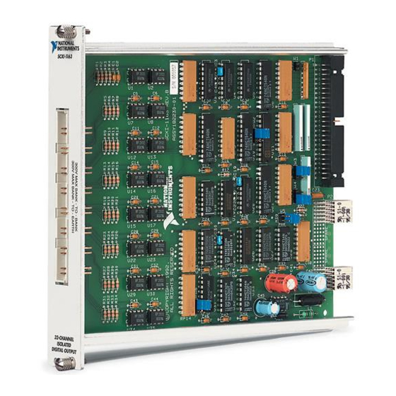
32-Channel Isolated Digital Output Module
Brand:
National Instruments
| Category:
Network Hardware
| Size: 0.81 MB
Table of Contents
User Manual
1
Limited Warranty
3
Table of Contents
4
About this Manual
8
Organization of this Manual
8
Conventions Used in this Manual
9
Related Documentation
10
Customer Communication
11
Chapter 1 Introduction
12
Figure 1-1. SCXI-1163 Digital Output Module
12
What You Need to Get Started
13
Optional Software
13
Optional Equipment
14
Custom Cables
14
Unpacking
15
Chapter 2 Configuration and Installation
16
Module Configuration
16
Jumper Use
19
Jumper Configuration
20
Jumper W4
20
Jumper W5
20
Jumpers W2 and W3
20
Jumper W6
21
Using Jumpers W4 and W5
21
Table 2-1. Configuration of Jumpers W2, W3, and W5 for DIO-Type and MIO-Type Boards
22
Table 2-2. Configuration of Jumpers W4 and W6
22
Hardware Installation
23
Signal Connections
23
Front Connector
24
Figure 2-2. SCXI-1163 Front Connector Pin Assignment
24
Front Connector Signal Descriptions
25
Terminal Block
26
SCXI-1326 Terminal Block
26
Signal Connection
27
SCXI-1326 Installation
29
Rear Signal Connector
29
Figure 2-4. SCXI-1163 Rear Signal Connector Pin Assignment
30
Rear Signal Connector Signal Descriptions, Serial Configuration
31
Rear Signal Connector Signal Descriptions, Parallel Configuration
31
Serial I/O Signal Connections
32
Table 2-3. Scxibus to SCXI-1163 Rear Signal Connector to Data Acquisition Board Pin Equivalences
33
Timing Requirements and Communication Protocol
34
Communication Signals
34
Figure 2-5. Slot-Select Timing Diagram
34
Figure 2-6. Serial Data Timing Diagram
35
Figure 2-7. Address Handler Timing Diagram
36
Figure 2-8. Data Register Write Timing Diagram
37
Figure 2-9. SCXI-1163 Module ID Register Timing Diagram
38
Figure 2-10. SCXI-1163 Status Register Timing Diagram
39
Chapter 3 Theory of Operation
40
Functional Overview
40
Scxibus Connector
40
Figure 3-1. SCXI-1163 Block Diagram
40
Figure 3-2. Scxibus Connector Pin Assignment
41
Scxibus Connector Signal Descriptions
42
Interface and Routing Circuitry
43
Figure 3-3. Digital Interface and Routing Circuitry Block Diagram
43
Table 3-1. Scxibus Equivalents for Rear Signal Connector
43
Register Circuitry
44
Figure 3-4. SCXI-1163 Register Circuitry
44
Optically Isolated Output Channels
45
Figure 3-5. SCXI-1163 Digital Output Diagram
46
Table 3-2. Channel and Bank Assignments
46
Chapter 4 Register Descriptions
47
Register Description
47
Register Description Format
47
SCXI-1163 Registers
47
Address Handler
48
Module ID Register
48
Table 4-1. SCXI-1163 Register Addresses
48
Data Register
50
Output Mode Status Register
51
Primary Mode Status Register
51
Status Registers
51
Parking Register
52
Slot 0 Register Descriptions
53
Slot-Select Register
54
Chapter 5 Programming
55
Programming Considerations
55
Notation
55
Register Writes
55
Register Selection and Write Procedure
56
Table 5-1. Scxibus to SCXI-1163 Rear Signal Connector to Data Acquisition Board Pin Equivalences
56
Initialization
57
Examples
58
Example 1
58
Example 2
58
Example 3
59
Appendix A Specifications
60
Digital Outputs
60
Physical
60
Operating Environment
61
Storage Environment
61
Appendix B Rear Signal Connector
62
Figure B-1. SCXI-1163 Rear Signal Connector Pin Assignment
63
Rear Signal Connector Signal Descriptions, Serial Configuration
64
Rear Signal Connector Signal Descriptions, Parallel Configuration
64
Appendix Cscxibus Connector
66
Figure C-1. Scxibus Connector Pin Assignment
67
Scxibus Connector Signal Descriptions
68
Appendix Dscxi-1163 Front Connector
69
Figure D-1. SCXI-1163 Front Connector Pin Assignment
70
Front Connector Signal Descriptions
71
Appendix Escxi-1163 Cabling
73
SCXI-1340 Cable Assembly
73
Table E-1. SCXI-1163 and Board Pinout Equivalences
74
SCXI-1340 Installation
75
Figure E-1. SCXI-1340 Installation
75
SCXI-1341 Lab-NB, Lab-PC, or Lab-PC+ and SCXI-1344 Lab-LC Cable Assembly
76
Table E-2. SCXI-1341 and SCXI-1344 Pin Translations
76
SCXI-1341 and SCXI-1344 Installation
77
SCXI-1342 PC-LPM-16 Cable Assembly
77
SCXI-1342 Installation
78
Table E-3. SCXI-1342 Pin Translations
78
DIO-96, AT-MIO-16D, and AT-MIO-64F-5 Board Connection
79
Table E-4. SCXI-1163 and DIO-96, AT-MIO-16D, and AT-MIO-64F-5 Board Pinout Equivalences
80
SCXI-1351 and NB5 Cable Installation
81
SCXI-1348 DIO-32F Cable Assembly
82
Figure E-2. SCXI-1351 and NB5 Cable Installation
82
Table E-5. SCXI-1348 Pin Translations
83
SCXI-1348 Installation
84
SCXI-1180 Feedthrough Panel
84
SCXI-1180 Installation
84
Figure E-3. SCXI-1180 Rear Connections
85
SCXI-1302 50-Pin Terminal Block
86
Figure E-4. SCXI-1180 Front Panel Installation
86
SCXI-1302 Wiring Procedure
86
SCXI-1302 Installation
87
SCXI-1351 One-Slot Cable Extender
87
Figure E-5. Cover Removal
87
SCXI-1351 Installation
88
Multiple-Chassis Connections for the SCXI-1163
88
Installation
88
SCXI-1343 Rear Screw Terminal Adapter
89
Table E-6. SCXI-1343 Pin Connections
89
SCXI-1343 Installation
90
Appendix F Customer Communication
91
Glossary
95
Index
97
Advertisement
Related Products
National Instruments SCXI-1120
National Instruments DAQ SCXI-1161
National Instruments SCXI-1121
National Instruments SCB-68
National Instruments SC-2040
National Instruments SCXI-1163R
National Instruments SCXI-116 Series
National Instruments SCXI-1162
National Instruments SCXI-1167
National Instruments SCXI-11603
National Instruments Categories
Control Unit
I/O Systems
Controller
Computer Hardware
Measuring Instruments
More National Instruments Manuals
Login
Sign In
OR
Sign in with Facebook
Sign in with Google
Upload manual
Upload from disk
Upload from URL