Sign In
Upload
Manuals
Brands
MSA Manuals
Security Sensors
Ultima X
MSA Ultima X Gas Detector Manuals
Manuals and User Guides for MSA Ultima X Gas Detector. We have
3
MSA Ultima X Gas Detector manuals available for free PDF download: Operating Manual, Instruction Manual Addendum, Instruction Manual
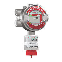
MSA Ultima X Operating Manual (42 pages)
Gas Monitors with X3 Technology
Brand:
MSA
| Category:
Gas Detectors
| Size: 0 MB
Table of Contents
Table of Contents
6
Safety Regulations
8
Correct Use
8
Liability Information
8
Safety and Precautionary Measures to be Adopted
9
Description
10
General View Gas Monitor
10
Components
11
Installation
13
Instructions for Installation
13
Installation with Mounting Kit
14
Electrical Connection for ULTIMA X 3 TM Instruments
15
Operation
17
4.1. Hand-Held Controller and Calibrator
17
Modbus Addressing
18
Modbus Communications
19
Supported Modbus Function Codes
19
Modbus Memory Map Overview
19
Modbus Base Address (Read/Write)
19
Modbus Factory Configuration Data (Read Only)
20
Calibration
21
Optional RESET Button
22
Modbus Port
23
Modbus Communications
23
Maintenance
24
Technical Data
25
Dimensions, Weight
25
Performance Specifications
25
Order Information
26
Appendix A Electrical Installation
27
A-1. Installation Drawings
27
A-2. Cable Lengths and Power Consumption
27
A-3. Connection Drawings
29
Appendix B Modbus User Configuration Data
30
Modbus User Configuration Data
30
B-2. Alarm Function Codes - Word 1
31
B-3. Alarm Function Codes - Word 2
31
B-4. Modbus Device Status
32
B-5. Modbus General Status Bits
33
B-6. Modbus Fault Status Bits
34
B-7. Control Words
34
B-8. Modbus Command Word 1
35
B-9. Modbus Command Word 2
35
B-10. Gas Type
36
B-11. Sensor Engineering Units
37
B-12. Information Flags Word 1
37
B-13. Information Flags Word 2
37
B-14. Information Flags Word 3
38
B-15. Information Flags Word 4
38
B-16. Alternate Gas Readings
39
Appendix C Option for Internal Relay
40
C-1. Relay Connections
40
Advertisement
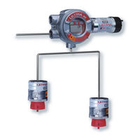
MSA Ultima X Instruction Manual (29 pages)
Sampling Module, DC Aspirated Model
Brand:
MSA
| Category:
Security Sensors
| Size: 0 MB
Table of Contents
Table of Contents
6
Chapter 1
8
General Information
8
Introduction
8
The Ultima X Sampling Module - Aspirated Model
8
Unpacking Unit
8
Figure 1-1. Sampling Module Installation
9
Unit Identification
10
Ultima X Sampling Module - Aspirated Model
11
Terminology
12
Chapter 2, Installation
13
General
13
Warning
13
Mounting the Aspirated Sampling Module Unit
14
(All Models)
14
Caution
14
Sample Line Placement between Aspirated Sampling Module and Ultima X Gas Monitor
15
Warning
15
Sample Line Placement
16
Caution
16
A Sampling Module
17
Caution
18
Exhaust Line Placement
19
Aspirator Connection
19
Warning
19
Electrical Connection
20
Electrical Connection Procedure
20
Caution
20
Warning
21
Initial Start-Up
22
Caution
22
Table 2-2. Wiring Identification
22
Chapter 3
24
Calibration and Operation
24
Introduction
24
Calibration Procedures
25
Equipment Needed
25
Zeroing the System with the Ultima X Sampling Module
25
Warning
25
Spanning with the Ultima X Sampling Module
26
Operation
26
Warning
26
Chapter 4, Maintenance and Troubleshooting Guidelines
27
Maintenance
27
Filter Maintenance
27
Troubleshooting Guidelines
28
Replacement Parts
29
MSA Ultima X Instruction Manual Addendum (30 pages)
Gas Monitors with X3 Technology
Brand:
MSA
| Category:
Measuring Instruments
| Size: 0 MB
Table of Contents
Table of Contents
2
Power
5
RS485 Communications
5
Section 1, Typical Modbus Network Topography (FIGURE 1-1)
5
Operation
10
Display
10
Relays
10
For Signal Boost Option
11
Figure 2-2. Sensor Display Screens
12
Alarm Status Screen
13
Sensor
13
Table 2-1. Status Indication Codes
14
Calibration
15
Ultima X Controller or Ultima X Calibrator
15
Modbus Communications
16
Warning
16
Section 2, Typical Communication Cable Wiring for Signal Boost (FIGURE 2-1)
10
Sensors
5
Transmitter Sensor Distance (FIGURE 1-3)
5
Wiring
5
Figure 1-1. Typical Modbus Network Topography
6
Table 1-1. Maximum Power Cable Length
7
Figure 1-2. Typical Communications Wiring Scheme
8
Figure 1-3. Signal-Boost Sensor Diagram
9
Section 3, Modbus
17
Modbus Addressing
17
Table 3-1. Supported Modbus Function Codes
17
Modbus Base Address (Read/Write)
18
Table 3-2. Modbus Memory Map Overview
18
Read Only
20
(Read/Write at Address Base+137)
21
(Read/Write at Address Base+138)
21
Table 3-8. Modbus Device Status (Read Only)
22
(Read Only at Address Base+201)
24
(Read Only at Address Base+202)
24
Table 3-11. Control Words (Read/Write)
25
(Read at Address Base+302/Write Coils 17 through 32)
26
Table 3-14. Sensor Type
26
Table 3-15. Sensor Engineering Units
27
(Read at Address Base+254)
28
(Read at Address Base+255)
28
Table 3-16. Information Flags
28
(Read at Address Base+257)
29
(Read at Address Base+26)
29
Table 3-18. Information Flags
29
Advertisement
Advertisement
Related Products
MSA Ultra Elite Series
MSA Ultra Elite-PF
MSA Ultra Elite-PF-EZ
MSA Ultra Elite-PF Small
MSA Ultra Elite-PS-Small
MSA Ultra Elite-PS-EZ
MSA Ultra Elite-PS-MaXX
MSA Ultra Elite-PS-MaXX Small
MSA Ultra Elite-PF-ESA
MSA Ultra Elite-PF-ESA Small
MSA Categories
Safety Equipment
Respiratory Product
Security Sensors
Gas Detectors
Motorcycle Accessories
More MSA Manuals
Login
Sign In
OR
Sign in with Facebook
Sign in with Google
Upload manual
Upload from disk
Upload from URL