Sign In
Upload
Manuals
Brands
Mitsubishi Manuals
Touch terminals
F940GOT-SWD-E
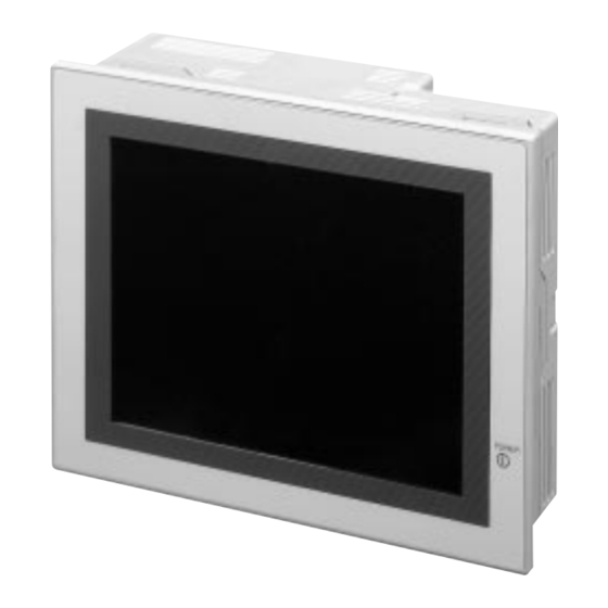
Mitsubishi F940GOT-SWD-E Manuals
Manuals and User Guides for Mitsubishi F940GOT-SWD-E. We have
4
Mitsubishi F940GOT-SWD-E manuals available for free PDF download: Operation Manual, Hardware Manual, Installation Manual
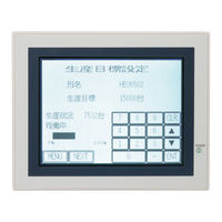
Mitsubishi F940GOT-SWD-E Operation Manual (300 pages)
Graphic operation terminals Melsec-GOT
Brand:
Mitsubishi
| Category:
Touch terminals
| Size: 3.2 MB
Table of Contents
Table of Contents
9
1 Introduction
15
Outline
15
Function List
18
Format of Manual
21
Contents Described in Manual
21
Abbreviations Used in Text
21
Expressions and Basic Operations of Operation Keys
22
Expressions of Operation Keys
22
Basic Operations
22
System Configuration
23
Enlarged View of Connector
23
Connection of Peripheral Units of GOT
24
Connection of Peripheral Units of PLC
25
Connection of PLC
27
Setting of Connected PLC
27
Connection of MELSEC FX/A Series (CPU PORT)
27
Connection of MELSEC a Series (LINK PORT)
28
Connection of SYSMAC C Series
29
Connection by General-Purpose Communication
34
2 Start up
43
Start up Procedure
43
Operation Environment Setting
45
Each Mode Selection Procedure
51
Security Function (Screen Protection Function)
53
3 Screen Mode
55
Outline of Screen Mode
55
Change of Displayed Data
57
Common Contents in Data Change
57
Numeric Setting Completion Flag
59
When FX-PCS-DU/WIN-E Is Used
59
When SW¨D5C-GOTRE-PACK Is Used
60
4 HPP Mode
61
Outline of HPP Mode
61
Program List
62
Parameter
71
Device Monitor
72
Device/Comment Monitor
72
Changing of Set Values and Current Values of T, C and D
74
Forced ON/OFF
76
List Monitor
77
Active State Monitor
78
Bfm Monitor
79
Pc Diagnosis
80
5 Sampling Mode
81
Outline of Sampling Mode
81
Outline of Sampling Condition Setting
83
Sample Cond
85
Start Cond
86
End Cond
87
Sampling Dev
89
Display of Sampling Result
90
Display List
90
Display Graph
90
Clear Data
91
Control Signals in PLC
92
When Screen Creation Software DU/WIN Is Used
92
When Screen Creation Software GOT-A900 Is Used
92
6 Alarm Mode
93
Outline of Alarm Function
93
Alarm Function in Screen Mode
94
Alarm Function in Alarm Mode
97
Operation When Alarms Have Occurred
98
Alarm List
99
Alarm History Display
101
Alarm Frequency Display
102
Alarm History Clear
103
7 Test Mode
105
Outline of Test Mode
105
User Screen
106
Data Bank
107
Debug
108
8 Other Mode
111
Outline of Other Mode
111
Set Time Switch
112
Data Transfer
113
Print out
114
Entry Code
116
Set up Mode
117
9 Creation of Display Screens
119
Outline of Compatibility of Screen Data
120
Functions Dedicated to Screen Creation Software for du
121
Common Functions
122
Functions Dedicated to Screen Creation Software for GOT-A900
125
Transfer of Screen Data
126
Use of Data in FX-50DU-TK(S)-E
128
Concept on Screen Display
129
Screen Display Position
129
Number of Display Screens and Screen Nos
129
Number of Display Elements and Data Capacity
130
Attribute of Display Element
131
Screen Call Function and Overlay Function
132
Screen Call Function
133
Overlay Function
134
Control Devices and System Information
142
Control Device (Setting in FX-PCS-DU/WIN-E)
142
System Information (Setting in Software for GOT-A900)
145
10 Creation of Display Screens (FX-PCS-DU/WIN-E)
149
Element List
149
Registration of Object
152
Display Objects
153
Text
153
Line
154
Box
155
Filled Box
156
Circle
157
Filled Circle
158
Image
159
Date and Time
160
Data Display Objects
161
Library Text
161
Number
163
Bar Graph
167
Circle Graph
170
Proportional Bar Graph
171
Proportional Pie Graph
172
Panel Meter
173
Indicator
174
Label Indicator
175
10.4.10 Text Indicator
176
10.4.11 Image Indicator
177
10.4.12 Overlay Screen
178
10.4.13 Library Image
179
Trend Graph (Sampling)
180
Trend Graph (Total)
183
10.4.16 Ascii
185
Data Transfer Objects
188
Touch Key
192
Switch
193
Send Data Bank (Recipe Function)
195
Write Constant
196
Increment
197
Decrement
198
Data Setting
199
Keyboard
202
Change Screen
205
10.5.10 Buzzer
206
Text Library
207
Image Library
208
Data File
209
11 Changeover of Display Screen (FX-PCS-DU/WIN-E)
211
Outline of Changeover of Display Screen
211
Change Screen" Object
212
Contents of Setting
212
Operation of Screen Changeover
214
Timing of Screen Changeover
215
Screen Changeover by Touch Key
216
Screen Changeover from PLC
219
Screen Changeover Using Bit Devices
219
Screen Changeover by Data
221
Screen Changeover by Screen No. Stored in Memory
223
Changeover to System Screen
225
Application of Screen Changeover
226
12 Creation of Display Screen (SW¨D5C-GOTRE-PACK)
229
Element List
229
Figure Display Function
231
Data Display Function
232
Display of Numerics
232
ASCII Code Display Function
234
Clock Display Function
237
Comment Display Function
238
Alarm History Display Function
239
Alarm List Display Function
241
Part Display Function
243
Lamp Display Function
244
Panel Meter Display Function
245
Graph Display Function
246
Trend Graph
247
Line Graph
248
Bar Graph
249
Statistics Graph Display Function
251
Touch Keys
252
Common Items for All Touch Keys
253
Bit Function
255
Word Function
257
Creation of Keys to Enter Numerics and ASCII Codes
258
Data Input Function
259
Numerical Input Function
259
ASCII Code Input Function
261
Creation of Comment
264
Recipe Function
265
13 Creation of Display Screens (SW¨D5C-GOTRE-PACK)
267
Outline of Changeover of Display Screen
267
Changeover of Display Screen
268
Contents of Setting
268
Contents of Screen Changeover Operation
268
Changeover of Base Screen (Changeover from PLC)
269
Outline of Changeover of Base Screen
269
Example of Changeover of the Base Screen
270
Screen Changeover by Touch Key
271
Changeover Using a Fixed Value
271
Changeover to Upper Hierarchy
272
Changeover to System Screen
273
Display Example of System Screen
273
Application of Screen Changeover
274
Application Example 1
274
Application Example 2
276
14 Additional Functions (in Ver. 3.00 or Later)
277
Outline of Additional Functions
277
Connection to Bar Code Reader
278
Communication Specifications
278
Setting of System Information (Control Devices)
278
Write to PC
280
Example of PC Program
281
Troubleshooting
282
Connection to PC Manufactured by Allen-Bradley
283
Setting of Communication
283
Device List
284
Connection to MELSEC-Qna Series
286
CPU Direct Connection
286
Computer Link Connection
286
Screen Hard Copy Function
287
Outline of Hardware Copy Operation
287
Starting and Aborting Printing
288
Printing Image
290
Additional Key Codes
291
Key Window Display Position Specification
292
Appendix: System Screen No.
295
Appendix: Key Code
295
Appendix: Key Code List
295
Screen Creation Sheet
297
Advertisement
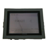
Mitsubishi F940GOT-SWD-E Hardware Manual (112 pages)
Graphic Operation Terminals
Brand:
Mitsubishi
| Category:
Touch terminals
| Size: 1.89 MB
Table of Contents
Table of Contents
7
Introduction
9
Outline of Product
10
Product Configuration
16
System Configuration
22
Installation, Wiring and General Specifications
29
Installation of Main Body
29
Wiring of Power Supply
32
Functions of Operation Keys and Connectors
37
Outside Dimensions
40
General Specificationsl
41
Connection to Personal Computer
43
CPU Port Connection
46
Computer Link Port Connection (MELSEC a Series)
54
Connection to SYSMAC C Series
57
Connection to FLEX-PC N Series
60
Connection by General-Purpose Communication
63
Startup
67
Startup Procedure
68
Operation Environment Setting
71
Extension Module
85
Data Transfer Adaptor
85
Maintenance
89
Outline of Maintenance
89
Replacement of Battery
91
Replacement of Backlight
93
Troubleshooting
95
Power Indication
95
Additional Functions (in Ver3.00 or Later)
99
Applicable Versions and Models
99
Connection to MELSEC Qna Series PC
100
Connection to SLC 500 Series
101
Connection to Bar Code Reader
103
Screen Hard Copy Function
105
Additional Function in Alarm History Display
106
Specification of Ten-Key Window Initial Display Position
106
Additional Functions (in V3.10 or Later)
107
Applicable Versions and Models
107
Additional Functions (in V4.00 or Later)
109
Applicable Versions and Models
109
Mitsubishi F940GOT-SWD-E Hardware Manual (41 pages)
Brand:
Mitsubishi
| Category:
Touch terminals
| Size: 1.17 MB
Table of Contents
Table of Contents
6
System Configuration
8
When the GOT Is Directly Connected to the PLC
8
When Built-In Two-Port Interface Function Is Used
10
Connection to Personal Computer
14
Pin Assignment and Connection Diagram of Transfer Cables
15
CPU Port Connection
18
Connection to FX/A Series
18
Connection Diagram
20
Connection of Two or more GOT Units
21
Computer Link Port Connection (MELSEC a Series)
26
Connection Diagram
27
Connection to SYSMAC C Series
30
Connection Diagram
31
Connection to FLEX-PC N Series
34
Connection Diagram
35
Connection by General-Purpose Communication
38
Outline
38
Connection Diagram
40
Communication Setting
41
Advertisement
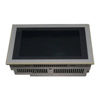
Mitsubishi F940GOT-SWD-E Installation Manual (8 pages)
MELSEC-GOT Graphic Operation Terminals
Brand:
Mitsubishi
| Category:
Touch terminals
| Size: 0.49 MB
Table of Contents
Specifications
3
Installation
4
Power Supply Wiring
5
Expansion Module
5
Maintenance
6
Advertisement
Related Products
Mitsubishi F940GOT-LWD-E
Mitsubishi F940
Mitsubishi F940GOT Handy Series
Mitsubishi F9Q
Mitsubishi F9Q1
Mitsubishi F9Q2
Mitsubishi FX3U-20SSC-H
Mitsubishi FX-16EYR-TB
Mitsubishi FX-40DU-TK-ES
Mitsubishi FX0S-24
Mitsubishi Categories
Air Conditioner
Controller
Projector
Automobile
Engine
More Mitsubishi Manuals
Login
Sign In
OR
Sign in with Facebook
Sign in with Google
Upload manual
Upload from disk
Upload from URL