Sign In
Upload
Manuals
Brands
Mitsubishi Electric Manuals
Controller
MR-J5D-G
Mitsubishi Electric MR-J5D-G Manuals
Manuals and User Guides for Mitsubishi Electric MR-J5D-G. We have
3
Mitsubishi Electric MR-J5D-G manuals available for free PDF download: User Manual
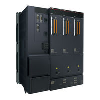
Mitsubishi Electric MR-J5D-G User Manual (194 pages)
Hardware
Brand:
Mitsubishi Electric
| Category:
Controller
| Size: 29.73 MB
Table of Contents
Safety Instructions
3
About the Manual
5
U.s. Customary Units
6
Table of Contents
7
Chapter 1 Introduction
11
Wiring Procedure
11
Combination with Converter Units and Drive Units
12
Combination with Power Regeneration Converter Units and Drive Units
12
Combination with Drive Units and Servo Motors
14
Rotary Servo Motor
14
Wiring Check
16
Power Supply System Wiring
16
I/O Signal Wiring
17
Surrounding Environment
18
Chapter 2 Installation
19
Mounting Direction and Clearances
20
Installation
20
Mounting Hole Location Diagram
21
Keeping out Foreign Materials
23
Cable Stress
23
Fan Unit Replacement Procedure
23
List of Applicable Fan Units
23
Fan Unit Removal Procedure
24
Fan Unit Installation Procedure
25
IP20 Compatible Terminal Block
26
Side Protection Cover
26
Side Protection Cover Installation Procedure
27
Restrictions When Using this Product at an Altitude Exceeding 1000 M and up to 2000 M
28
Installing the Mounting Attachment
29
Selection of Attachment for Power Regeneration Converter Units
30
Selecting the Attachment for Drive Units
32
Dimensions When Installing the Mounting Attachment
33
Chapter 3 Signals and Wiring
43
Example Power Circuit Connections
44
Drive Unit Termination Settings
44
How to Use the Bus Bar
49
Example I/O Signal Connections
50
Mr-J5D1-_G
51
Mr-J5D2-_G_/Mr-J5D3-_G
53
Explanation of Power Supply System
56
Explanation of Signals
56
Power-On Procedure
56
Wiring CNP3
58
Connectors and Pin Assignments
61
Precautions
61
Connectors and Pin Assignments
62
Signal (Device) Explanation
64
Input Device
64
Output Device
68
Output Signal
73
Power Supply
74
Interface
75
Internal Connection Diagram
75
Detailed Explanation of Interfaces
79
Source I/O Interface
82
Servo Motor with an Electromagnetic Brake
83
Connection Diagram
83
Grounding
85
Chapter 4 Dimensions
86
400 V Class
86
Connector
93
CN3 Connector
93
SCR Connector System (3M)
93
Chapter 5 Characteristics
94
Overload Protection Characteristics
94
Power Supply Capacity and Generated Loss
96
Power Supply Capacity
96
Generated Loss
96
Dynamic Brake Characteristics
98
Dynamic Brake Operation
99
Cable Flex Life
114
Inrush Currents at Power-On of Control Circuit
115
Chapter 6 Options and Peripheral Equipment
116
Cables/Connector Sets
116
Combinations of Cables/Connector Sets
117
MR-D05UDL3M-B STO Cable
119
Ethernet Cable
120
Bus Bar
121
MR Configurator2
122
Engineering Tool
122
Precautions for Using USB Communication Function and Ethernet Communication Function
122
Selection Example of Wires
123
Molded-Case Circuit Breakers, Fuses
125
Selection Example (for Control Circuit Power Supply)
125
Selection Examples that Comply with IEC/EN/UL 61800-5-1 and CSA C22.2 No.274
127
Relay (Recommended)
128
Noise Reduction Techniques
128
Noise Reduction Products
133
Earth-Leakage Current Breaker
136
Chapter 7 Absolute Position Detection System
137
Outline
137
Characteristics
137
Restrictions [G]
137
Precautions
137
System Architecture
138
Servo Parameter Setting [G]
138
Homing
138
Checking the Detected Absolute Position Data
139
Procedure of Replacing a Servo Motor with Battery-Less Absolute Position Encoder
139
Configuration and Specifications
140
Connecting the Battery-Less Encoder
140
Chapter 8 Using Sto Function
141
Introduction
141
Outline
141
Terms Related to Safety
141
Precautions
141
Residual Risks of the STO Function
142
Specifications
143
Maintenance
143
Functional Safety I/O Signal Connector (CN8) and Pin Assignments
144
Pin Assignment
144
Signal (Device) Explanation
144
How to Pull out the STO Cable
145
Connection Example
146
Precautions for Compliance with Stop Category 1 (IEC/EN 60204-1)
146
Precautions for Compliance with Stop Category 0 (IEC/EN 60204-1)
146
Connection Example for CN8 Connector
147
External I/O Signal Connection Example Using an External Safety Relay Unit
148
Detailed Explanation of Interfaces
149
Sink I/O Interface
149
Source I/O Interface
151
Chapter 9 Using Functional Safety
152
Function Block Diagram
152
Safety Sub-Function Control by Input Device
152
Safety Sub-Function Control by Network
153
System Architecture
154
Safety Sub-Function Control by Input Device
154
Safety Sub-Function Control by Network
155
Specifications
156
Connectors and Pin Assignments
156
Example I/O Signal Connections
157
Input Signal
157
Output Signal
158
Connecting I/O Interfaces
159
Source Input
159
Sink Input
159
Wiring the SBC Output
160
Noise Reduction Techniques
161
Example of Connection with Other Devices
162
Safety Sub-Function Control by Input Device
162
Safety Sub-Function Control by Network
163
Chapter 10 Using a Fully Closed Loop System
164
Precautions
164
Functions and Configuration
165
Outline
165
Function Block Diagram
166
Operation Mode and Load-Side Encoder Combinations
167
System Architecture
168
Signals and Wiring
171
Encoder Cable Configuration Diagram
171
Startup
173
Servo Parameter Setting
173
Checking Position Data of the Load-Side Encoder
178
Basic Functions
179
Homing
179
Operation from Controller
183
Fully Closed Loop Control Error Detection Function
183
About MR Configurator2
185
Options and Peripheral Equipment
187
MR-J4FCCBL03M Branch Cable
187
Absolute Position Detection System
188
Revisions
190
Warranty
191
Trademarks
192
Advertisement
Mitsubishi Electric MR-J5D-G User Manual (110 pages)
AC Servo System
Brand:
Mitsubishi Electric
| Category:
Controller
| Size: 5.06 MB
Table of Contents
Safety Instructions
3
About the Manual
5
U.s. Customary Units
5
Table of Contents
6
CHAPTER 1 CC-Link IE TSN
8
Functions and Configuration
8
Outline
8
System Configuration
8
Function List
9
Communication Specifications
10
Establishing and Disconnecting the Communication
11
Summary of Object Dictionary (OD)
11
Engineering Tool
13
Startup
14
Outline
14
Network Setting
14
Application Function
16
CC-Link IE TSN Network Diagnostics
16
IP Address Setting Function
17
Parameter Automatic Setting
18
Hold/Clear of Output at CPU STOP and at CPU Stop Error
19
Remote Reset
19
Clock Function
19
Motion Mode (High-Speed) Setting
20
Appendix
21
CC-Link IE TSN Communication Protocol
21
Cyclic Transmission
23
Transient Transmission
35
Drive Profile
35
Setting of Positioning Data
55
CHAPTER 2 CC-Link IE Field Network Basic
56
Functions and Configuration
56
Outline
56
System Configuration
56
Function List
57
Communication Specifications
58
Establishing and Disconnecting the Communication
59
Summary of Object Dictionary (OD)
59
Engineering Tool
61
Startup
62
Outline
62
Network Setting
62
Application Function
65
CC-Link IE Field Network Basic Diagnostics
65
IP Address Setting Function
65
Hold/Clear of Output at CPU STOP and at CPU Stop Error
66
Remote Reset
66
Appendix
67
Cyclic Transmission
67
Slmp
83
Drive Profile
89
Revisions
106
Warranty
107
Trademarks
108
Mitsubishi Electric MR-J5D-G User Manual (76 pages)
AC Servo System
Brand:
Mitsubishi Electric
| Category:
Controller
| Size: 10.67 MB
Table of Contents
Safety Instructions
3
About the Manual
5
Disposal of Waste
5
U.s. Customary Units
7
Table of Contents
8
Chapter 1 Specifications
10
Outline
10
Model Designation
10
Combination with Drive Units and Servo Motors
11
Drive Unit Standard Specifications
12
Mr-J5D1-_G
12
Mr-J5D2-_G
13
Mr-J5D3-_G
14
Positioning Mode
15
Functional Safety
16
Environment
18
Function Block Diagram
19
Mr-J5D1-_G
19
Mr-J5D2-_G_/Mr-J5D3-_G
20
Configuration Including Peripheral Equipment
21
Special Specifications
22
Drive Units Without the Dynamic Brake (-ED)
22
Chapter 2 Function
23
Restrictions on the MR-J5_-_G
23
Restrictions on CC-Link IE TSN
23
Restrictions on CC-Link IE Field Network Basic
23
2.2 Function List
24
Security
34
Chapter 3 Structure
35
Parts Identification
35
Switch Setting and Display of the Drive Unit
38
Switches
38
7-Segment LED
40
Status Leds
44
Chapter 4 Startup
45
Turning on Drive Unit for the First Time
49
Test Operation of the Servo Motor Alone in Test Operation Mode
50
Equipment Configuration Setting
51
Controller-Related Setting
52
Operation by Controller Command
53
Instructions on Startup
54
Troubleshooting at Startup
54
Duplicate Setting
55
Duplication Using MR Configurator2
55
Test Operation
55
Execution Method
55
Test Operation Mode
56
Motor Driving by Test Operation
57
Motor-Less Operation
60
Output Signal (DO) Forced Output
61
Drive Unit Setting Initialization
62
Initialization Procedure by MR Mode Change
62
Chapter 5 Maintenance, Inspection and Parts Replacement
63
Inspection Items
63
Periodic Inspection
63
Parts with a Service Life
63
Replacing Fan Unit
64
Chapter 6 Compliance with Global Standards
65
Compliance with Global Standards
65
Handling of AC Servo Amplifier Batteries for the United Nations Recommendations on the Transport of Dangerous Goods
65
Symbol for the New EU Battery Directive
68
Compliance with China Compulsory Certification (CCC)
69
Compliance with the China Rohs Directive
70
Revisions
72
Warranty
73
Trademarks
74
Advertisement
Advertisement
Related Products
Mitsubishi Electric MR-J5D
Mitsubishi Electric MR-J5D-G-N1
Mitsubishi Electric MELSERVO MR-J5-200G
Mitsubishi Electric MELSERVO MR-J5-200G4
Mitsubishi Electric MELSERVO MR-J5-10 Series
Mitsubishi Electric MELSERVO MR-J5-20 Series
Mitsubishi Electric MELSERVO MR-J5-40 Series
Mitsubishi Electric MELSERVO MR-J5-350 Series
Mitsubishi Electric MR-J5-B
Mitsubishi Electric MELSERVO MR-J5-700 Series
Mitsubishi Electric Categories
Air Conditioner
Controller
Projector
Inverter
Heat Pump
More Mitsubishi Electric Manuals
Login
Sign In
OR
Sign in with Facebook
Sign in with Google
Upload manual
Upload from disk
Upload from URL