Mitsubishi 900 Series Manuals
Manuals and User Guides for Mitsubishi 900 Series. We have 5 Mitsubishi 900 Series manuals available for free PDF download: User Manual
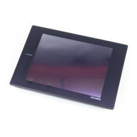
Mitsubishi 900 Series User Manual (146 pages)
Graphic Operation Terminal
Brand: Mitsubishi
|
Category: Touch terminals
|
Size: 26 MB
Table of Contents
Advertisement

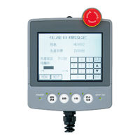
Mitsubishi 900 Series User Manual (146 pages)
Brand: Mitsubishi
|
Category: Touch Panel
|
Size: 7 MB
Table of Contents
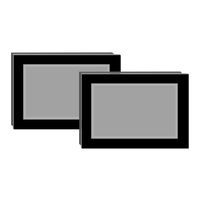
Mitsubishi 900 Series User Manual (126 pages)
Graphic Operation Terminal
Brand: Mitsubishi
|
Category: Touch terminals
|
Size: 7 MB
Table of Contents
Advertisement
Mitsubishi 900 Series User Manual (102 pages)
Graphic Operation Terminal
Brand: Mitsubishi
|
Category: Touch terminals
|
Size: 2 MB
Table of Contents
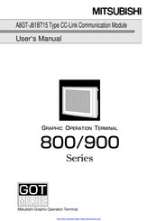
Mitsubishi 900 Series User Manual (72 pages)
Type CC-Link Communication Module, Graphic Operation Terminal
Brand: Mitsubishi
|
Category: Control Unit
|
Size: 0 MB