Sign In
Upload
Manuals
Brands
Lantronix Manuals
Server
Micro125
Lantronix Micro125 Manuals
Manuals and User Guides for Lantronix Micro125. We have
2
Lantronix Micro125 manuals available for free PDF download: User Manual, Integration Manual
Lantronix Micro125 User Manual (74 pages)
device server
Brand:
Lantronix
| Category:
Server
| Size: 0.66 MB
Table of Contents
User Guide
1
Copyright and Trademark
2
Warranty
2
Contacts
2
Disclaimer
2
Revision History
2
Table of Contents
3
List of Figures
6
List of Tables
6
1 Using this Guide
7
Purpose and Audience
7
Chapter Summary
7
Additional Documentation
8
2 Introduction
9
Capabilities
9
Applications
9
Protocol Support
10
Configuration Methods
10
Addresses and Port Numbers
10
Hardware Address
10
IP Address
11
Port Numbers
11
3 Getting Started
12
Physically Connecting the Unit
12
Required Information
12
Hardware Address
12
Figure 3-1. Evaluation Board Connected to Serial Device and Network
12
IP Address
13
4 Using Deviceinstaller
14
Installing Deviceinstaller
14
Assigning an IP Address
14
Accessing the Micro125 Using Deviceinstaller
15
Viewing the Current Configuration
15
5 Configuration Using Web Manager
18
Accessing Web-Manager Using Deviceinstaller
18
Figure 5-1. Web-Manager Login Window
19
Figure 5-2. Lantronix Web-Manager
19
Network Configuration
20
Network Mode
20
Automatic IP Address Configuration
20
Figure 5-3. Network Settings
20
Static IP Address Configuration
21
Ethernet Configuration
22
Server Configuration
23
Figure 5-4. Server Settings
23
Advanced
24
Host List Configuration
24
Retry Settings
25
Host Information
25
Channel 1 and Channel 2 Configuration
25
Figure 5-5. Hostlist Settings
25
Figure 5-6. Channel Serial Settings
26
Serial Settings
26
Connection Settings - TCP
29
Figure 5-7. TCP Connection Settings
29
Connect Protocol
30
Common Options
31
Disconnect Mode
31
Endpoint Configuration
31
Connection Settings - UDP
32
Figure 5-8. UDP Connection Settings
32
Apply Settings
33
Apply Defaults
34
Figure 5-9. Applying Settings
34
Figure 5-10. Applying Default Settings
34
6 Configuration Via Telnet or Serial Port (Setup Mode)
35
Accessing Setup Mode
35
Telnet Connection
35
Serial Port Connection
36
Figure 6-1. MAC Address
36
Figure 6-2. Setup Menu Options
36
Exiting Setup Mode
37
7 Setup Mode: Server Configuration
38
Server Configuration (Option 0)
38
IP Address
38
Table 7-1. Bootp/Dhcp/Autoip Options
38
Set Gateway IP Address
39
Netmask: Number of Bits for Host Part
39
Set DNS Server IP Address
39
Table 7-2. Standard IP Network Netmasks
39
Change Telnet/Web-Manager Password
40
DHCP Name
40
8 Setup Mode: Channel Configuration
41
Channels
41
Baudrate
41
Figure 8-1. Serial Port Parameters
41
I/F (Interface) Mode
42
I/F Mode
42
Table 8-1. Interface Mode Options
42
Table 8-2. Common Interface Mode Settings
42
Flow
43
Port Number
43
Table 8-3. Interface Mode Options
43
Table 8-4. Flow Control Options
43
Table 8-5. Reserved Port Numbers
43
Connect Mode
44
Table 8-6. Connect Mode Options
44
A) Incoming Connection
45
B) Response
45
C) Active Startup
45
Table 8-7. Manual Connection Address Example
46
Figure 8-2. Hostlist Option
47
D) Datagram Type
48
E) Modem Mode
48
Table 8-8. Modem Modes
48
Table 8-9. Modem Mode Messages
49
Send the Escape Sequence (+++) in Modem Mode
50
Table 8-10. Modem Mode Commands
50
Show IP Addr after 'RING
51
Auto Increment Source Port
51
Remote IP Address
51
Remote Port
51
Disconnmode
51
Table 8-11. Disconnect Mode Options
52
Flush Mode (Buffer Flushing)
53
Pack Control
53
Table 8-12. Flush Mode Options
53
Table 8-13. Pack Control Options
53
Packing Interval
54
Send Characters
54
Trailing Characters
54
Disconntime (Inactivity Timeout)
54
Send Characters
55
Telnet Terminal Type
55
Channel (Port) Password
55
9 Setup Mode: Advanced Settings
56
Expert Settings (Option 5)
56
TCP Keepalive Time in Seconds
56
Figure 9-1. Expert Settings
56
Table 9-1. Expert Settings: Details Settings
56
ARP Cache Timeout in Seconds
57
Disable Monitor Mode at Bootup
57
HTTP Port Number
57
MTU Size
57
TCP Re-Transmission Timeout
57
Enable Alternate MAC
57
Ethernet Connection Type
57
Security Settings (Option 6)
58
Disable SNMP
58
SNMP Community Name
58
Disable Telnet Setup
58
Figure 9-2. Security Settings
58
Disable TFTP Firmware Upgrade
59
Disable Port 77FE (Hex)
59
Disable Web Server
59
Disable Web Setup
59
Disable ECHO Ports
59
Enable Encryption
59
Enable Enhanced Password
60
Default Settings (Option 7)
61
Channel 1 and Channel 2 Configuration Defaults
61
Expert Settings Defaults
61
Security Settings Defaults
62
10 Firmware Upgrades
63
Obtaining Firmware
63
Reloading Firmware
63
Using TFTP: Graphical User Interface
63
Table 10-1. Firmware Files
63
Using TFTP: Command Line Interface
64
Figure 10-1. TFTP Window
64
Recovering the Firmware Using the Serial Port and Deviceinstaller
65
11 Monitor Mode
66
Entering Monitor Mode Using the Serial Port
66
Entering Monitor Mode Using the Network Port
66
Monitor Mode Commands
66
Table 11-1. Monitor Mode Commands
67
Table 11-2. Command Response Codes
68
12 Troubleshooting
69
Problems and Error Messages
69
Technical Support
72
A: Binary to Hexadecimal Conversions
73
Converting Binary to Hexadecimal
73
Conversion Table
73
Scientific Calculator
74
Advertisement
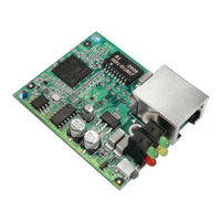
Lantronix Micro125 Integration Manual (19 pages)
Embedded Device Server
Brand:
Lantronix
| Category:
Network Card
| Size: 0.54 MB
Table of Contents
Copyright and Trademark
2
Contacts
2
Disclaimer and Revisions
2
Table of Contents
3
List of Figures
4
List of Tables
4
1 : Introduction Embedded Integration Kits
5
About the Integration Guide
5
Table 1-1 Micro125 Part Numbers
5
Chapter Summaries
6
Additional Documentation
6
1 : Introduction
5
2 : Description and Specifications
7
The Micro125
7
Layout and Dimensions
8
Figure 2-1 Micro125 Board Layout
8
Figure 2-2 Micro125 Top View
8
Connectors
9
Figure 2-3 Micro125 Connector End View
9
Figure 2-4 Micro125 Connectors
9
Ethernet Interface
10
Figure 2-5 RJ45 Ethernet Connector
10
Table 2-1 Micro125 Connector Pinouts
10
Status Leds
11
Figure 2-6 Micro125 Status Leds
11
Table 2-2 Micro125 Status Leds
11
Product Information Label
12
Technical Specifications
12
Figure 2-7 Product Label
12
Table 2-3 Micro125 Technical Specifications
12
3 : Integration Guidelines
14
Power Supply
14
Network Connector
14
Virtual Ground
15
Serial Signals
15
Additional Emission Improvements
15
Figure 3-1 Multi-Layer Board Strategy
15
4 : Test Bed
16
Board Layout
16
Figure 4-1 Carrier Board
16
Test Bed Connectors
17
Figure 4-2 Pin Configurations
17
Table 4-1 Micro125 Test Bed Connectors
17
A: Compliance and Warranty Information Compliance Information
18
Rohs Notice
19
Warranty
19
Advertisement
Related Products
Lantronix MSS
Lantronix MSS4
Lantronix MSS100
Lantronix MatchPort AR
Lantronix MatchPort b/g Pro
Lantronix MSS4-S
Lantronix MSS4-SFP
Lantronix MSS4-DFP
Lantronix Device Server MSS 485
Lantronix MSS Series
Lantronix Categories
Server
Switch
Network Hardware
Gateway
Print Server
More Lantronix Manuals
Login
Sign In
OR
Sign in with Facebook
Sign in with Google
Upload manual
Upload from disk
Upload from URL