Sign In
Upload
Manuals
Brands
Lantronix Manuals
Server
MatchPort b/g Pro
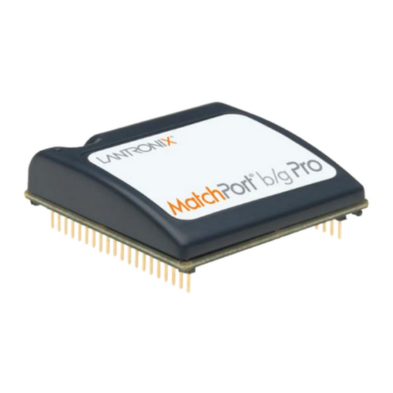
Lantronix MatchPort b/g Pro Manuals
Manuals and User Guides for Lantronix MatchPort b/g Pro. We have
2
Lantronix MatchPort b/g Pro manuals available for free PDF download: Command Reference Manual, Integration Manual
Lantronix MatchPort b/g Pro Command Reference Manual (166 pages)
Embedded Device Server
Brand:
Lantronix
| Category:
Server
| Size: 1 MB
Table of Contents
Command Reference
1
Copyright and Trademark
2
Revision History
2
Table of Contents
3
List of Figures
4
List of Tables
5
1 : about this Guide
6
Chapter Summaries
6
Conventions
6
Additional Documentation
7
2 : Overview
8
XML Architecture and Device Control
8
Command Line Interface
8
3 : Command Line Interface
9
Configuration Using Telnet
9
Configuration Using Serial Ports
9
Serial Command Mode
9
Serial Recovery
9
Navigating the CLI Hierarchy
10
Using Keyboard Shortcuts and CLI
11
Understanding the CLI Level Hierarchy
11
Figure 3-1 CLI Level Hierarchy
12
Figure 3-2 Login Level Commands
13
Figure 3-3 Enable Level Commands
13
4 : Configuration Using XML
14
XML Configuration Record Document Type Definition
14
Figure 4-1 DTD for Xcrs
14
Quick Tour of XML Syntax
15
Declaration
15
Element Start and End Tags
15
Element Attributes
15
Figure 4-2 XML Example
15
Record, Group, Item, and Value Tags
16
Figure 4-3 XML Group Example
16
Figure 4-4 XML Example of Multiple Named Values
16
Importing and Exporting an XML Configuration File
17
Figure 4-5 XML Example of Multiple Items
17
Figure 4-6 XML Example with Multiple Groups
17
Best Practices
18
Importing
18
Exporting
19
Passwords in the XML File
19
XML Configuration Groups
20
Figure 4-7 XML Example of Supplying Passwords
20
Table 4-8 XCR Groups
20
XML Status Record Groups and Items
33
5 : Configuration Using XML
44
Table 5-1 Commands and Levels
47
Advertisement
Lantronix MatchPort b/g Pro Integration Manual (33 pages)
embedded device server
Brand:
Lantronix
| Category:
Server
| Size: 2 MB
Table of Contents
Copyright and Trademark
2
Disclaimer and Revisions
2
Table of Contents
4
Contents
4
List of Figures
5
List of Tables
5
1: Introduction
6
1 : Introduction about the Integration Guide
6
Additional Documentation
6
2 : Description and Specifications
7
Matchport B/G Pro Block Diagram
7
Figure 2-1. Matchport B/G Pro Block Diagram
8
Matchport B/G Pro Pinouts
9
Power and Ground
9
Reset
10
Ethernet Connections
10
Figure 2-2. Connection Diagram to an RJ45 Jack
10
Ethernet LED Connections
11
Wireless LED Connections
11
Antenna Mating Connector
11
Figure 2-3. Recommended LED Connections
11
Figure 2-4. Recommended LED Connections
11
Antenna
12
Figure 2-5. Reverse-SMA to U.FL (P/N 500-180-R)
12
Figure 2-6. U.FL to U.FL Cable (P/N 500-181-R)
12
Figure 2-7. R-SMA Antenna Connector Dimensions (Not to Scale)
12
Serial Input/Output
13
Sample Layouts for RS485 Connectivity
13
Figure 2-8. Combined RS232/422 Transceiver
13
Table 2-1. RS232 Connections
13
Table 2-2. JP6 RS422/485 Connections on Demo Board
13
Figure 2-9. Separate RS232/422 Transceivers
14
IO Configurable Pins (Cps)
15
Figure 2-10. Separate RS422 Transceivers for 2-Wire and 4-Wire Setups
15
Bootp_En
16
BOOTP Enable
16
Diagnostics LED
16
Pin Connection Options
16
Electrical Specifications
17
Figure 2-11. BOOTP_EN# APPLICATION CIRCUIT
17
Table 2-3. Absolute Maximum Ratings
17
Table 2-4. Recommended Operating Conditions
17
Wireless Specifications
18
Technical Specifications
18
Table 2-5. Wireless Specifications
18
Table 2-6. Specifications
18
Dimensions
19
Figure 2-12. Side Views
19
Figure 2-13. Top View
20
Figure 2-14. Bottom View
20
Recommended PCB Layout
21
Figure 2-15. PCB Layout (Top View)
21
Product Information Label
22
Figure 2-16. Product Label
22
3 : Demonstration Kit
23
Contents of the Kit
23
Demo Board Description
23
Serial Interfaces
24
Power Supply
24
General Control
24
Table 3-1. RS-232 Signals on Serial Port 1
24
Table 3-2. RS-422 4-Wire Connector on Serial Port 1
24
Configuration Switch Bank
25
Table 3-3. Demo Board JP1 Jumper Configuration
25
Table 3-4. Demo Board JP7 Jumper Configuration for CON1
25
Table 3-5. Demo Board JP8 Jumper Configuration for CON2
25
Table 3-6. Demo Board JP8 Jumper Configuration for CON2
25
Table 3-7. Demo Board JP5 Jumper Configuration
26
Table 3-8. Demo Board Configurable Pin Jumper Configurations
26
Demo Board Layout
27
Figure 3-1. Matchport Demo Board Layout
27
Demo Board Schematics
28
Figure 3-2. Demo Board Block Diagram
28
Figure 3-3. Schematic
29
A: Compliance
32
B: Warranty
33
Advertisement
Related Products
Lantronix MatchPort AR
Lantronix MatchPort b/g
Lantronix MSS4
Lantronix MSS100
Lantronix MSS4-D
Lantronix MSS4-S
Lantronix MSS4-SFP
Lantronix MSS4-DFP
Lantronix Device Server MSS 485
Lantronix MSS1-T
Lantronix Categories
Server
Switch
Gateway
Network Hardware
Print Server
More Lantronix Manuals
Login
Sign In
OR
Sign in with Facebook
Sign in with Google
Upload manual
Upload from disk
Upload from URL