Sign In
Upload
Manuals
Brands
Kodak Manuals
Medical Equipment
CR 360
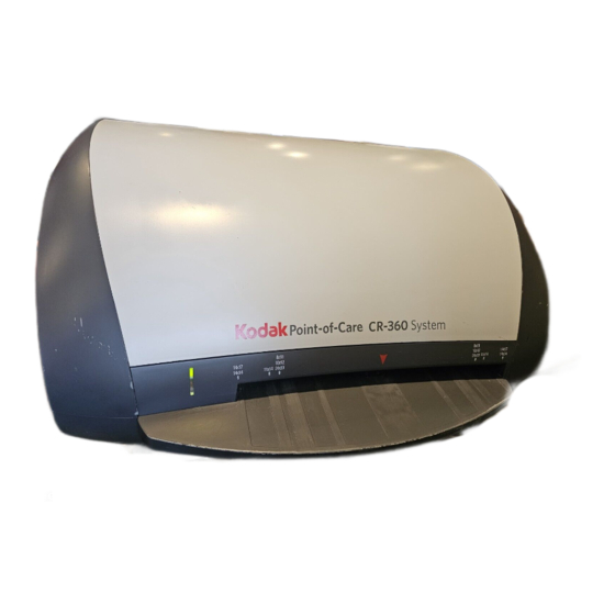
Kodak CR 360 Computed Radiography System Manuals
Manuals and User Guides for Kodak CR 360 Computed Radiography System. We have
1
Kodak CR 360 Computed Radiography System manual available for free PDF download: Service Manual
Kodak CR 360 Service Manual (216 pages)
Brand:
Kodak
| Category:
Medical Equipment
| Size: 6 MB
Table of Contents
Table of Contents
3
General Safety Guidelines
9
Safety and Regulatory Information
9
Introduction
9
Electrical Hazards
10
Explosion and Implosion Hazards
10
Overheating
10
Laser Safety Instructions
10
Recycling the Unit
11
Labelling Summary
11
IEC Symbols Used
11
Device-Specific Safety Information
12
Regulatory Information
12
Introduction
12
CE Conformity
12
USA Regulations
12
System Description
13
Introduction
13
Operational Principles
13
System Overview
14
Component Names and Descriptions
14
Views of the Point-Of-Care CR 360
16
Component Description
18
Power Line Filter Module
18
IMCS Board
18
Linear Slide Assembly
19
Overview
19
Two Types of Linear Screws
19
Optical Head Assembly
20
Linear Motor
20
Photo Multiplier Assembly (PM)
21
Loader Stepper Assembly
22
Roller Drive Motor Assembly
22
Right and Left Limit Sensors
23
Service Procedures
24
Service Tools
24
Removing the Scanner Cover
25
Installing the Scanner Cover
25
Activating the Scanner Without the Cover (Laser Deactivated)
26
Before Service Operations
26
Activation Procedures
26
Activating the Scanner Without the Cover
26
After Service Operations
27
Activating the Scanner Without the Cover (Laser Activated)
27
Before Service Operations
27
Replacing the Power Line Filter Module
28
Tools Required
28
Removing the Power Line Filter Module
28
Installing the Power Line Filter Module
29
Procedure
30
Tools Required
30
Replacing the Fuses
30
Tools Required
32
Removing the Controller Board
32
Replacing the Controller Board
32
Installing the Controller Board
34
Replacing the IMCS Board
36
Tools Required
36
Removing the IMCS Board
36
Separating the Sensor Board from the Motion Board
37
Installing the IMCS Board
38
Removing the PM Board
39
Replacing the Photo Multiplier Board
39
Tools Required
39
Installing the PM Board
40
Replacing the Photo Multiplier Assembly
41
Tools Required
41
Removing the PM Tube
41
Installing the PM Tube
43
Replacing the Optical Head Assembly
45
Tools Required
45
Removing the Optical Head Assembly
45
Installing the Optical Head Assembly
46
Removing the Linear Screw Type a
48
Replacing the Linear Screw Type a
48
Tools Required
48
Installing the Linear Screw Type a
49
Replacing the Linear Screw Type B
50
Tools Required
50
Removing the Linear Screw Type B
50
Installing the Linear Screw Type B
52
Test Procedure
53
Removing the Linear Motor Type a
54
Tools Required
54
Replacing the Linear Motor Type a
54
Installing the Linear Motor Type a
56
Replacing the Linear Motor Type B
58
Tools Required
58
Removing Type B Linear Motor
58
Installing the Linear Motor Type B
61
Replacing the Roller Drive Motor Assembly
64
Tools Required
64
Removing the Drive Roller Motor Assembly
64
Installing the Roller Drive Motor
65
Replacing the Loader Stepper Assembly
67
Tools Required
67
Removing the Loader Stepper Assembly
67
Installing the Loader Stepper Assembly
67
Replacing the Laser Board
69
Tools Required
69
Removing the Laser Board
69
Installing the Laser Board
70
Removing the Power Supply Unit
71
Tools Required
71
Replacing the Power Supply
71
Installing the Power Supply Unit
75
Replacing the Erase Lamps Assembly
77
Tools Required
77
Removing the Erase Lamps Assembly
77
Installing the Erase Lamps Assembly
78
Installing the Erase Lamps Fuse
80
Test Procedure
80
Tools Required
80
Replacing the Erase Lamps Fuse
80
Replacing the Erase Lamp Board
81
Tools Required
81
Removing the Erase Lamp Board
81
Installing the Erase Lamp Board
81
Replacing the Erase Lamps Inverter Board
82
Tools Required
82
Removing the Erase Lamps Inverter Board
82
Installing the Erase Lamps Inverter Board
82
Tools Required
83
Removing the Roof Assembly
83
Introduction
83
Replacing the Roof Assembly and Tray Assembly
83
Removing the Tray Assembly
85
Installing the Tray Assembly and the Roof Assembly
86
Test Procedure
87
Replacing the Right and Left Limit Sensors
88
Tools Required
88
Removing the Right Limit Sensor
88
Installing the Right Limit Sensor
89
Removing the Left Limit Sensor
89
Installing the Left Limit Sensor
90
Installing the LED Indicator
91
Tools Required
91
Replacing the LED Indicator
91
Removing the LED Indicator
91
LED Indicator Test Procedure
92
Replacing the Cassette Status Sensors
93
Tools Required
93
Removing the Cassette Status Sensors
93
Installing the Cassette Status Sensors
93
Cassette Status Sensors Test Procedure
94
Removing the Cassette Fixation Lever Assembly
95
Replacing the Cassette Fixation Lever Assembly
95
Tools Required
95
Installing the Casette Fixation Lever Assembly
97
Replacing the W0 Sensor
98
Tools Required
98
Removing the W0 Sensor
98
Installing the W0 Sensor
99
W0 Sensor Test Procedure
100
Installing the Z0 Sensor
101
Removing the Z0 Sensor
101
Tools Required
101
Replacing the Z0 Sensor
101
Z0 Sensor Test Procedure
102
Installing the IGUS Energy Chain
103
Tools Required
103
Procedure
103
Testing and Closing the Scanner Cover
109
Replacing the Barcode Reader
110
Tools Required
110
Removing the Barcode Reader
110
Installing the Barcode Reader
111
Calibrations
114
Equipment Required
114
Introduction
114
The Calibrations Tab
114
Origin Calibration
115
Offset Calibration
116
System Gain Tuning
117
Purpose
117
System Gain Tuning Procedure
117
OCPC Process Calibration
118
Purpose
118
OCPC Process Calibration Procedure
118
Adjustment Procedure
120
Adjusting the Cassette Release Mechanism
120
Tools Required
120
Adjustments
120
Auto-Loop Solenoid Test
124
Introduction
124
Tools Required
124
Solenoid off Test (Go/No Go)
125
Solenoid on Test (Touch/No Touch)
128
Adjustment Procedure
129
Adjusting the Plate Pusher
129
Tools Required
129
Preventive Maintenance
130
Cleaning the Rollers
130
Roller Cleaning Cycles
130
Roller Cleaning Procedure
130
Dismissing the Roller Cleaning Reminder
133
Cleaning the Phosphor Screens
134
Introduction
134
Cleaning the Phosphor
134
Cleaning the Scanner
134
Key Operator Settings
135
Accessing Advanced Settings
135
User Tab
136
Setup Tab
138
Anatomical Tab
140
Diagnostics Tab
141
SW Update & Backup Tab
144
Backing up (Export) Scanner and Anatom Settings
145
To Restore (Import) Scanner and Anatom Settings
145
Updating Firmware, FPGA, and NIOS Settings
145
Calibration Tab
146
Admin Tab
147
About Tab
148
DICOM Settings-Settings Tab
149
DICOM Settings-Destinations Tab
151
Electrical Diagrams
152
Block Diagram #1: Modular Power Supply
152
Block Diagram #2
153
Block Diagram #3
154
Block Diagram #4
155
Block Diagram #5
156
Block Diagram #6
157
Block Diagram #7
158
Block Diagram # 8
159
Block Diagram #9
160
Observable Conditions
161
Troubleshooting
161
Section 10: Hardware Error Messages
163
Hardware Error Message Index
163
Hardware Error Messages
163
Introduction
163
Device Error #10: "Linear Motor Commutation Error
164
Device Error #1: "Linear Axis Motor Position Error Failure
164
Device Error #2: "Linear Axis Motor Encoder Failure
164
Device Error #4: "Linear Motor Peak over Current Failure
164
Device Error #7: "Linear Homing Cycle was Not Completed
164
Hardware Error Messages
164
Recommended Action by Field Engineer
164
Scenario
164
Device Error #3: "Linear Motor Continuous over Current
165
Recommended Actions for Field Engineer
165
Scenario
165
Device Error #21: "Rotation Motor under Voltage
166
Device Error #5: "Linear Motor under Voltage
166
Recommended Actions for Field Engineer
166
Scenario
166
Device Error #22: "Rotation Motor over Voltage
167
Device Error #38: "Roller Motor over Voltage
167
Device Error #6: "Linear Motor over Voltage
167
Recommended Actions for Field Engineer
167
Scenario
167
Device Error #17: "Rotation Motor Position Error Failure
168
Device Error #18: "Rotation Motor Encoder Failure
168
Device Error #19: "Rotation Motor Continuous over Current
168
Device Error #20: "Rotation Motor Peak over Current
168
Device Error #23: "Rotation Motor Commutation Error
168
Recommended Actions for Field Engineer
168
Scenario
168
Device Error #33: "Roller Motor Position Error Failure
169
Device Error #34: "Roller Motor Encoder Failure
169
Recommended Actions for Field Engineer
169
Scenario
169
Device Error #40: "W0 Sensor Is in Wrong State
170
Recommended Actions for Field Engineer
170
Scenario
170
Device Error #41: "Loop Sensor Is in Wrong State
171
Recommended Actions for Field Engineer
171
Scenario
171
Device Error #39 "Plate Carriage Stuck
172
Device Error #42: "Plate Carriage Stuck
172
Recommended Actions for Field Engineer
172
Scenario
172
Device Error #49: "Loader Motor Fault
173
Device Error #55: "Loader Homing Cycle was Not Completed
173
Recommended Actions for Field Engineer
173
Scenario
173
Device Error #57: "Loader DID Not Reach Back Sensor
174
Recommended Actions for Field Engineer
174
Scenario
174
Device Error #58: "Plate DID Not Reach W0
175
Recommended Actions for Field Engineer
175
Scenario
175
Device Error #59: "Cassette Release Failure
176
Recommended Actions for Field Engineer
176
Scenario
176
Recommended Actions for Field Engineer
177
Scenario
177
Device Error #70: "Communication Error with IMCS
178
Recommended Actions for Field Engineer
178
Scenario
178
Device Error #82: "CCFL Power Supply Failure
179
Recommended Actions for Field Engineer
179
Scenario
179
Device Error #92: "Erase Lamps Are Not Working
180
Recommended Actions for Field Engineer
180
Scenario
180
Controller and IMCS Embedded Software Update
181
Updating Firmware and FPGA
181
Updating the Controller Files
181
Updating the IMCS Embedded Files
182
Establishing Communication between the Host Computer and the IMCS Board
185
Installing the SC Shell Application
185
Introduction
185
Using the SC Shell Application
185
VSP Option
185
Direct Cable Option
186
Creating a Communication Terminal in the SC Shell Application
187
Opening the Communication Terminal in the SC Shell Application
188
Loading Custom Commands
189
Downloading Firmware
191
Verifying the Firmware Download
193
Downloading Macros
194
Verifying the Macro Download
196
Downloading Parameters
197
Measuring the Linear Motor Current
199
Verifying Parameters Download
199
Acceptance Test Procedure
204
Preparing the Unit for Testing
204
Scope
204
Tools Required
204
Dark Noise
205
System Response and Linearity
206
Uniformity and Artifacts
207
Multiple Test Tools: Resolution Grid, Step Wedge, and Contrast Resolution
208
Erasure Efficiency
209
Inspecting the Low Contrast Resolution
209
Inspecting the Spatial Resolution
209
Inspecting the Step Wedge
209
Image Quality Results Reporting
210
Appendix
212
Calibration Results Report
212
Test Target Tool for Barcode Alignment Procedure
213
Publication History
214
Advertisement
Advertisement
Related Products
Kodak CR 7400
Kodak DirectView CR 800 System
Kodak DirectView CR 825
Kodak DirectView CR 850
Kodak DirectView CR 500 System
Kodak VERITE CRAFT 6
Kodak Point-of-Care CR 120 System
Kodak Point-of-Care CR 140 System
Kodak PIXPRO CZ42
Kodak Carousel 700
Kodak Categories
Digital Camera
Scanner
Printer
Projector
All in One Printer
More Kodak Manuals
Login
Sign In
OR
Sign in with Facebook
Sign in with Google
Upload manual
Upload from disk
Upload from URL