Sign In
Upload
Manuals
Brands
Keithley Manuals
Multimeter
2010
User Manuals: Keithley 2010 Digit Multimeter
Manuals and User Guides for Keithley 2010 Digit Multimeter. We have
3
Keithley 2010 Digit Multimeter manuals available for free PDF download: User Manual, Service Manual, Quick Reference Manual
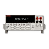
Keithley 2010 User Manual (277 pages)
Brand:
Keithley
| Category:
Multimeter
| Size: 2 MB
Table of Contents
Safety Precautions
4
Table of Contents
6
1 General Information
18
Introduction
19
Feature Overview
19
Warranty Information
20
Manual Addenda
20
Safety Symbols and Terms
20
Specifications
20
Inspection
21
Options and Accessories
21
Scanner Cards
21
General Purpose Probes
21
Low Thermal Probes
22
Cables and Adapters
22
Rack Mount Kits
23
Carrying Case
23
2 Basic Measurements
24
Introduction
25
Front Panel Summary
26
Figure 2-1 Model 2010 Front Panel
26
Basic Measurements
27
Basic Measurements
28
Rear Panel Summary
29
Figure 2-2 Model 2010 Rear Panel
29
Power-Up
31
Line Power Connection
31
Figure 2-3 Power Module
31
Setting Line Voltage and Replacing Fuse
32
Table 2-1 Fuse Ratings
32
Power-Up Sequence
33
High Energy Circuit Safety Precautions
34
Power-On Defaults
35
Table 2-2 Factory Defaults
36
GPIB Primary Address
38
Warm-Up Time
38
Display
39
Status and Error Messages
39
Measuring Voltage
39
Connections
39
Crest Factor
40
Low Level Considerations
40
Figure 2-4 DC and AC Voltage Measurements
40
Thermal Emfs
41
Ac Voltage Offset
42
Ratio
43
Connections
43
Measuring Voltage with the SENSE Terminals
44
Using Ratio with the Relative Function
44
Measuring Current
45
Connections
45
Figure 2-5 DC and AC Current Measurements
45
AMPS Fuse Replacement
46
Measuring Resistance
47
Connections
47
Shielding
48
Low Resistance Measurements
48
Figure 2-6 Two- and Four-Wire Resistance Measurements
48
Dry Circuit Testing
49
Offset Compensation
49
Figure 2-7 Offset-Compensated Ohms Measurement
50
Measuring Frequency and Period
51
Trigger Level
51
Gate Time
51
Connections
52
Figure 2-8 Frequency and Period Measurements
52
Measuring Temperature
53
Connections
54
Figure 2-9 Thermocouple and RTD Temperature Measurements
54
Configuration
55
Math
55
User Rtd Type
55
MX + B
56
Dbm Calculation
57
Percent
57
Db Calculation
58
Measuring Continuity
59
Connections
59
Threshold Resistance Level
59
Figure 2-10 Continuity Measurements
59
Testing Diodes
60
Connections
60
Range
60
Figure 2-11 Diode Testing
60
3 Measurement Options
62
Introduction
63
Measurement Configuration
63
Range
63
Maximum Readings
63
Manual Ranging
63
Filter
64
Figure 3-1 Moving Average and Repeating Filters
65
Filter Types
65
Response Time
65
Relative
66
Digits
66
Rate
67
Table 3-1 Rate Settings for the Measurement Functions
68
Trigger Operations
69
Trigger Model
69
Control Source and Event Detection
69
Table 3-2 Auto Delay Settings
70
Device Actions
71
Reading Hold (Autosettle)
71
External Triggering
72
Figure 3-3 Rear Panel Pinout
72
Hold Example
72
Figure 3-4 Trigger Link Input Pulse Specifications (EXT TRIG)
73
Figure 3-5 Trigger Link Output Pulse Specifications (VMC)
73
Specifications
73
External Trigger
73
Voltmeter Complete
73
External Triggering Example
73
Figure 3-6 DUT Test System
74
Figure 3-7 Trigger Link Connections
74
Figure 3-8 Operation Model for Triggering Example
75
Figure 3-9 DIN to BNC Trigger Cable
76
External Triggering with Bnc Connections
76
Buffer Operations
77
Storing Readings
77
Recalling Readings
77
Figure 3-10 Buffer Locations
78
Buffer Statistics
78
Limit Operations
79
Setting Limit Values
79
Enabling Limits
80
Figure 3-11 Using Limits Test to Sort 100Ω, 10% Resistors
80
Scan Operations
81
Scanning Overview
81
Front Panel Scanner Controls
81
Using an Internal Scanner Card
81
Using External Scanner Cards
81
Using the and Keys
82
Using OPEN and CLOSE Keys
82
Stepping and Scanning Trigger Model Additions
83
Figure 3-12 Front Panel Triggering with Stepping
83
Using SHIFT-CONFIG to Configure Stepping and Scanning
84
Figure 3-13 Front Panel Triggering with Scanning
84
Scanning Examples
85
Figure 3-14 Internal Scanning Example with Reading Count Option
85
Figure 3-15 Internal Scanning Example with Timer and Delay Options
88
External Scanning
89
System Operations
91
Self-Test
91
Calibration
91
4 Remote Operation
92
Introduction
93
Selecting an Interface
93
Rs-232
93
GPIB Bus
94
Selecting a Language
94
Table 4-1 Language Support
94
Keithley Models 196/199 Digital Multimeter
95
Scpi
95
Operation
96
Sending and Receiving Data
96
Selecting Baud Rate
96
Selecting Signal Handshaking (Flow Control)
97
Setting Terminator
97
Connections
98
Error Messages
98
Figure 4-1 RS-232 Interface Connector
98
GPIB Bus Operation and Reference
99
Introduction
99
GPIB Bus Standards
99
GPIB Bus Connections
99
Figure 4-2 IEEE-488 Connector
99
Figure 4-3 IEEE-488 Connections
100
Figure 4-4 IEEE-488 Connector Location
100
Selecting the Primary Address
101
Quickbasic 4.5 Programming
101
Install the Universal Language Driver
101
About Program Fragments
102
General Bus Commands
103
Llo (Local Lockout)
104
Gtl (Go to Local)
104
Dcl (Device Clear)
104
Sdc (Selective Device Clear)
105
Get (Group Execute Trigger)
105
Spe, Spd (Serial Polling)
105
Front Panel GPIB Operation
106
Error and Status Messages
106
Gpib Status Indicators
106
Local Key
106
Status Structure
107
Figure 4-5 Model 2010 Status Register Structure
107
Condition Registers
108
Enable Registers
108
Event Registers
108
Figure 4-6 Standard Event Status
109
Figure 4-7 Operation Event Status
109
Figure 4-8 Measurement Event Status
110
Figure 4-9 Questionable Event Status
110
Error Queue
111
Output Queue
111
Queues
111
Figure 4-10 Status Byte and Service Request (SRQ)
112
Status Byte and Service Request (SRQ)
112
Status Byte Register
112
Service Request Enable Register
113
Serial Poll and Srq
114
Trigger Model (GPIB Operation)
115
Idle and Initiate
116
Trigger Model Operation
116
Figure 4-12 Device Action (Trigger Model)
117
Programming Syntax
118
Command Words
118
Commands and Command Parameters
118
Query Commands
120
Case Sensitivity
120
Long-Form and Short-Form Versions
120
Short-Form Rules
121
Program Messages
121
Single Command Messages
122
Multiple Command Messages
122
Command Path Rules
123
Program Message Terminator (Pmt)
123
Command Execution Rules
123
Response Messages
124
Message Exchange Protocol
124
Sending a Response Message
124
Multiple Response Messages
124
Response Message Terminator (Rmt)
124
Common Commands
125
CLS - Clear Status
125
ESE <Nrf> - Event Enable
126
ESE? - Event Enable Query
126
ESR? - Event Status Register Query
127
Figure 4-13 Standard Event Enable Register
127
Figure 4-14 Standard Event Status Register
128
IDN? - Identification Query
129
OPC - Operation Complete
129
OPC? - Operation Complete Query
131
OPT? - Option Identification Query
132
RCL - Recall
132
Rst - Reset
133
SAV - Save
133
SRE <Nrf> - Service Request Enable
133
SRE? - Service Request Enable Query
133
Figure 4-15 Service Request Enable Register
134
STB? - Status Byte Query
135
TRG - Trigger
136
TST?-Self-Test Query
136
Figure 4-16 Status Byte Register
136
WAI - Wait-To-Continue
137
5 SCPI Command Reference
138
SCPI Signal Oriented Measurement Commands
139
Configure Command
139
Fetch? Command
140
READ? Command
141
Measure Command
142
SCPI Command Subsystems Reference Tables
143
Calculate Subsystem
157
Calculate[1]
157
Table 5-11 UNIT Command Summary
157
Calculate2
159
Calculate3
161
Display Subsystem
163
Format Subsystem
165
DATA Command
165
Figure 5-1 ASCII Data Format
165
Figure 5-2 IEEE754 Single Precision Data Format (32 Data Bits)
166
Figure 5-3 IEEE754 Double Precision Data Format (64 Data Bits)
166
Border Command
167
Elements Command
168
Route Subsystem
169
Single Channel (or Channel Pair) Control
169
Multiple Channel Control
171
SCAN Commands
172
[Sense[1]] Subsystem
174
Function Command
174
DATA Command
175
HOLD Command
176
Speed Commands
177
Range Commands
178
Reference <N> Commands
180
Dcircuit Command
182
Ocompensated Command
182
Digits Command
183
Average Commands
184
Bandwidth Command
185
Threshold Commands
186
Transducer Commands
186
Thermocouple Commands
187
FRTD Commands
189
Diode Command
190
Continuity Command
191
Status Subsystem
191
[:Event]? Command
191
Figure 5-4 Measurement Event Register
192
Figure 5-5 Questionable Event Register
193
Figure 5-6 Operation Event Register
194
Enable Command
195
Figure 5-7 Measurement Event Enable Register
196
Figure 5-8 Questionable Event Enable Register
196
Figure 5-9 Operation Event Enable Register
196
Condition? Command
197
Preset Command
197
Queue Commands
198
System Subsystem
201
Beeper Command
201
Preset Command
201
Kclick Command
201
Posetup <Name> Command
202
Version? Command
202
Error? Command
203
Azero Commands
204
Clear Command
204
KEY <Nrf> Command
205
Figure 5-10 Key-Press Codes
206
Interface Commands
207
Line Frequency Query
207
Trace Subsystem
208
Clear Command
208
FREE? Command
208
Points Command
208
FEED Command
209
DATA? Command
209
Trigger Subsystem
210
Initiate Commands
210
Abort Command
210
Trigger Commands
211
UNIT Subsystem
213
Temperature Command
213
Voltage Commands
214
Specifications
216
Specifications
217
Math Functions
220
Accuracy Calculations
221
Calculating DC Characteristics Accuracy
221
Calculating AC Characteristics Accuracy
221
Calculating Dbm Characteristics Accuracy
222
Calculating Db Characteristics Accuracy
223
Additional Derating Factors
223
Optimizing Measurement Accuracy
224
Optimizing Measurement Speed
224
DC Voltage, DC Current, and Resistance
224
Status and Error Messages
226
Table B-1 Status and Error Messages
227
Example Programs
232
Program Examples
233
Changing Function and Range
233
One-Shot Triggering
235
Generating SRQ on Buffer Full
236
Storing Readings in Buffer
237
Taking Readings with the Scanner Card
239
Taking Readings Using the :READ? Command
243
Controlling the Model 2010 Via the RS-232 COM2 Port
243
Models 196/199 Commands
247
500 D Models 196/199 Commands
249
Table D-1 Models 196/199 Device-Dependent Command Summary
249
IEEE-488 Bus Overview
252
Introduction
253
Bus Description
253
Bus Lines
255
Data Lines
255
Bus Management Lines
255
Handshake Lines
256
Figure E-2 IEEE-488 Handshake Sequence
256
Bus Commands
257
Uniline Commands
258
Universal Multiline Commands
258
Addressed Multiline Commands
259
Address Commands
259
Unaddress Commands
259
Common Commands
260
SCPI Commands
260
Table E-2 Hexadecimal and Decimal Command Codes
260
Figure E-3 Command Codes
261
Typical Command Sequences
262
Table E-3 Typical Addressed Command Sequence
262
Table E-4 Typical Addressed Command Sequence
262
IEEE Command Groups
263
Table E-5 IEEE Command Groups
263
Interface Function Codes
264
IEEE-488 and SCPI Conformance Information
266
Introduction
267
Table F-2 Coupled Commands
268
Advertisement
Keithley 2010 Service Manual (134 pages)
Multimeter
Brand:
Keithley
| Category:
Measuring Instruments
| Size: 3 MB
Table of Contents
Safety Precautions
5
Table of Contents
7
Introduction
15
Verification Test Requirements
15
Environmental Conditions
15
Warm-Up Period
15
Performance Verification
15
Line Power
16
Recommended Test Equipment
16
Verification Limits
17
Restoring Factory Defaults
17
Performing the Verification Test Procedures
18
Test Summary
18
Test Considerations
18
1 Performance Verification
19
Verifying DC Voltage
19
Figure 1-1 Connections for DC Volts Verification
19
Table 1-2 DCV Reading Limits
19
Verifying AC Voltage
20
Figure 1-2 Connections for AC Volts Verification
20
Table 1-3 ACV Reading Limits
20
Verifying DC Current
21
Figure 1-3 Connections for DC Current Verification
21
Table 1-4 DCI Limits
21
Verifying AC Current
22
Figure 1-4 Connections for AC Current Verification
22
Table 1-5 ACI Limits
22
Verifying Resistance
23
Figure 1-5 Connections for Resistance Verification (10Ω-10MΩ Ranges)
23
Figure 1-6 Connections for Resistance Verification (100MΩ Range)
24
Verifying Temperature
25
Thermocouple Temperature
25
RTD Temperature
26
Verifying Frequency
27
Verifying Ratio
27
Figure 1-7 Connections for Frequency Verification
27
Figure 1-8 Verifying Ratio
27
2 Calibration
28
Introduction
29
Environmental Conditions
29
Warm-Up Period
29
Line Power
29
Calibration Considerations
30
Calibration Code
30
Front Panel Code
30
Remote Command Code
31
Comprehensive Calibration
31
Calibration Cycle
31
Recommended Equipment
32
Aborting Calibration
32
Front Panel Calibration
33
Preparing the Model 2010 for Calibration
33
Front Panel Short and Open Calibration
34
Figure 2-1 Low-Thermal Short Connections
34
DC Volts Calibration
35
Resistance Calibration
36
DC Current Calibration
37
AC Voltage Calibration
38
Figure 2-4 Connections for AC Volts Calibration
38
AC Current Calibration
39
Setting Calibration Dates
39
Remote Calibration
40
Preparing the Model 2010 for Calibration
41
Short and Open Calibration
41
DC Volts Calibration
42
Table 2-8 DC Voltage Calibration Programming Steps
42
Resistance Calibration
43
DC Current Calibration
44
Table 2-10 DC Current Calibration Programming Steps
44
AC Voltage Calibration
45
AC Current Calibration
45
Programming Calibration Dates
46
Saving Calibration Constants
46
Locking out Calibration
46
Manufacturing Calibration
47
Firmware Revision Level
47
Recommended Test Equipment
47
Test Equipment Connections
48
Unlocking Manufacturing Calibration
49
Calibration for Firmware Revision A14 and Higher
49
Table 2-14 1V, 10Hz Frequency Errors
50
Calibration for Firmware Revision A13 and Lower
51
3 Routine Maintenance
53
Introduction
54
Setting the Line Voltage and Replacing the Line Fuse
54
Figure 3-1 Power Module
54
Replacing the AMPS Fuse
55
Table 3-1 Power Line Fuse
55
4 Troubleshooting
56
Introduction
57
Repair Considerations
57
Power-On Self-Test
57
Front Panel Tests
58
KEY Test
58
DISP Test
58
Principles of Operation
59
Power Supply
59
Figure 4-1 Power Supply Block Diagram
59
Figure 4-2 Digital Circuitry Block Diagram
59
Figure 4-3 Analog Circuitry Block Diagram
59
Table 4-1 Power Supply Components
59
Display Board
61
Digital Circuitry
61
Analog Circuitry
63
Troubleshooting
65
Display Board Checks
65
Table 4-2 Display Board Checks
65
Power Supply Checks
66
Table 4-3 Power Supply Checks
66
Digital Circuitry Checks
67
Analog Signal Switching States
68
Table 4-9 Ω2/Ω4 Reference Switching
70
Table 4-12 DCV Signal Multiplexing and Gain
71
Table 4-15 Ω2 Signal Multiplexing and Gain
72
No Comm Link Error
73
5 Disassembly
74
Introduction
75
Handling and Cleaning
75
Handling PC Boards
75
Solder Repairs
75
Static Sensitive Devices
76
Assembly Drawings
76
Case Cover Removal
77
Changing Trigger Link Lines
77
Motherboard Removal
78
Front Panel Disassembly
79
Main CPU Firmware Replacement
80
Removing Power Components
81
Power Transformer Removal
81
Power Module Removal
81
Instrument Re-Assembly
82
6 Replaceable Parts
87
Introduction
88
Parts Lists
88
Ordering Information
88
Factory Service
88
Component Layouts
88
Table 6-1 Mother Board Parts List
89
Table 6-2 Display Board Parts List
96
Table 6-4 Mechanical Parts List
97
Remote Interface
104
Specifications
105
Accuracy Calculations
105
Calculating DC Characteristics Accuracy
105
Calculating AC Characteristics Accuracy
105
Additional Derating Factors
106
Calibration Command Reference
108
Introduction
108
Command Summary
108
Miscellaneous Calibration Commands
110
DC Calibration Commands
114
AC Calibration Commands
118
Manufacturing Calibration Commands
120
Remote Error Reporting
120
Error Summary
121
Error Queue
123
Status Byte EAV (Error Available) Bit
123
Generating an SRQ on Error
123
Detecting Calibration Step Completion
123
Using the *OPC? Query
123
Using the *OPC Command
124
Generating an SRQ on Calibration Complete
124
Calibration Program
125
Introduction
126
Computer Hardware Requirements
126
Software Requirements
126
Calibration Equipment
126
General Program Instructions
127
Index
131
Service Form
133
Keithley 2010 Quick Reference Manual (60 pages)
Brand:
Keithley
| Category:
Multimeter
| Size: 0 MB
Table of Contents
Safety Precautions
7
Introduction
11
Front Panel Operation Summary
13
Measuring Continuity
19
Remote Operation Summary
31
Advertisement
Advertisement
Related Products
Keithley 2002
Keithley 2000
Keithley 2015
Keithley 2001
Keithley 2016
Keithley 2015P
Keithley 2100
Keithley 2700
Keithley 2110
Keithley 2000-Scan
Keithley Categories
Measuring Instruments
Multimeter
Test Equipment
Power Supply
Switch
More Keithley Manuals
Login
Sign In
OR
Sign in with Facebook
Sign in with Google
Upload manual
Upload from disk
Upload from URL