Sign In
Upload
Manuals
Brands
JRC Manuals
Marine Radar
JAN-9202
JRC JAN-9202 Manuals
Manuals and User Guides for JRC JAN-9202. We have
4
JRC JAN-9202 manuals available for free PDF download: Field Service Manual, Instruction Manual, Installation Manual
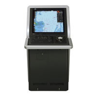
JRC JAN-9202 Field Service Manual (1078 pages)
MARINE RADAR EQUIPMENT, ECDIS CONNING DISPLAY
Brand:
JRC
| Category:
Marine Radar
| Size: 49.9 MB
Table of Contents
Contents
29
Table of Contents
31
Chapter 1 System Overview
39
Functions
41
Features
43
Scanner Units
46
Transmitter Receiver Units
49
Display Units
50
Chapter 2. System Configuration
55
Components
59
Power System Diagram
65
Function System Diagrams
71
Scanner Unit / Transmitter-Receiver Unit
71
Display Unit
77
I/O Specifications
81
CCU : Central Control Unit NDC-1590 I/O Specifications
81
PSU : Power Supply Unit NBD-913 I/O Specifications
88
SLC : Serial LAN Interface Circuit CMH-2370
91
AOC : Analog Option Circuit CMJ-560 I/O Specifications
101
GIF : Gyro Interface Circuit CMJ-554 I/O Specifications
103
RIF :Radar Interface Circuit CQD-2273 I/O Specifications
105
DIP-SW and Jumper Pin Settings
111
Setting for CQD-2273 Radar Interface Circuit
111
Settings for CMJ-554 Gyro Interface Circuit
113
Settings for CMH-2370 Serial LAN Interface Circuit
117
Settings for CMJ-560 Analog Option Circuit
130
Settings for NDC-1590 Central Control Unit: CCU
133
Settings for T/R Control Circuit CMC-1205R
137
Settings for NKE-1632 Scanner Unit
138
Settings for NKE-2632 Scanner Unit
139
Settings for NKE-2632-H Scanner Unit
140
Setting for UPS
141
Settings for Interswitch
142
Chapter 3. Repair Parts
147
List of Repair Parts
149
Parts Required for Periodic Replacement
149
Spares
150
Special Parts
150
Circuit Blocks
153
Exploded View Drawings
161
Chapter 4. Replacement Procedure
219
Replacement Procedures for Scanner Unit
222
Scanner Unit
222
Scanner Unit
228
Replacement Procedures for Display Unit
531
Inch Monitor Unit: MNU NWZ-208
535
Inch Monitor Unit: MNU NWZ-207
542
Inch Monitor Unit: MNU NWZ-214
549
Central Control Unit: CCU NDC-1590
554
Trackball Operation Unit: TOPU NCE-5605
615
Keyboard Operation Unit: KOPU NCE-5625
635
Power Supply Unit: PSU NBD-913
643
Junction Box: JB NQE-1143
652
Relay Terminal Block: CQD-2312
681
Sensor LAN Switch Unit: NQA-2443
692
Replacing the UPS
704
Detaching the Front Frame of the Display Unit Mount Kit
727
Setting up after Replacements
735
To Display the Service Menu for Engineers
735
Displaying the "Maintenance" Dialog Box
736
Setting up Anfter Replacing Scanner Units
737
Setting up Anfter Replacing Display Units
740
Chapter 5. Software Update
742
Updating the Software
744
Backing Up/Recovering Data
748
Backing up Data
748
Restoring Backup Data
750
Recovering the C Drive Image
752
Advertisement
JRC JAN-9202 Instruction Manual (332 pages)
Conning Display
Brand:
JRC
| Category:
Monitor
| Size: 9.64 MB
Table of Contents
Table of Contents
27
Section 1 Overview
35
Functions
36
Features
37
Components
38
General System Diagrams
54
Section 2 Name and Function of each Unit
57
Name and Main Function of the Operation Unit
57
Trackball Operation Unit
57
Keyboard Operation Unit (Option)
59
Display Unit
60
Names and Main Functions of the Top Screen
61
Conning Display Top Screen
61
Color Coding of Bar Graphs
63
Color-Coded Numeric Display
63
Numeric Box
63
Task Switching Button
64
Right Toolbar
64
Menu] Button
65
Alert Notification Area
65
Condition Where There Is an AMS License
65
Condition Where There Is no AMS License
65
Section 3 Basic Operations
67
Section 3 Basic Operations
67
Powering on and Starting
67
Starting each Mode
68
Starting Conning Display
68
Basic Operations When Using a Trackball
69
Trackball Functions
69
Basic Trackball Operations
69
Cursor Types
69
Basic Click Operations
70
Basic Menu Operations
71
Opening the Menu
71
Menu List
72
Closing the Menu
72
Basic Dialog Box Operations
73
Changing Dialog Box Settings
73
Closing the Dialog
74
Title Bar
75
Confirming and Acknowledging an Alert
76
Stopping a Buzzer
77
Confirming Alert Contents
77
Acknowledging the Alert
80
Displaying Alert List and Alert History
81
Switching between a Standard Window and an Extended Window
86
Switching the Day/Night Mode
88
Adjusting the Brightness of the Screen and Operation Unit
90
Adjusting the Brightness of the Screen
90
Adjusting the Brightness of the Operation Unit
91
Display Brightness] Dialog Box
92
MOB (man over Board)
93
Setting up the Timer
95
Setting up the Time
95
MULTI] Dial
96
Functions of [MULTI] Dial
96
Functions Assigned to [MULTI] Dial
96
Changing the Function that Is Assigned
96
Displaying a Screen for Setting the Function that Is Assigned
96
Basic Operations of the Software Keyboard
97
Starting a Software Keyboard
97
Name and Function of each Section of the Keyboard
98
Example of Numeric Input
101
Character Input Example
103
Setting a Date and a Time (Calendar Operation)
105
Details and Usage of a Calendar Picker
105
Details of a Calendar
105
How to Use a Calendar
106
Help
107
Password Input
110
Managing Files with File Manager
112
Displaying the [File Manager] Dialog Box
112
File Management
113
Returning to a Task Menu by Ending the Operation
116
Terminating this Equipment
117
Section 4 each Block of Conning Display
119
Switching to the Navigation Mode/Docking Mode/Custom Mode
120
How to View each Block
122
Block List
122
Block Name Example of the Shape of the Block
123
Selecting a Block to be Displayed on the Screen in Custom Mode
126
Description of each Block
130
Information about Azimuth Thruster of CPP (Controllable Pitch Propeller) Type
130
Navigation Information and the Legend of the
130
Navigation Information and the Legend of the Navigation
130
Information about Side Thruster of CCP (Controllable Pitch Propeller) Type
131
Information about Azimuth Thruster of FPP (Fixed Pitch Propeller) Type
132
Information about Propeller Engine of CPP (Controllable Pitch Propeller) Type
132
Propeller) Type
132
Information about Propeller Engine of FPP (Fixed Pitch Propeller) Type
133
Information about Side Thruster of FPP (Fixed Pitch Propeller) Type
133
N-UP/H-UP Switching Button
134
N-UP/H-UP Switching Buttons
134
Ship Block
134
Azimuth Thruster Information (with Status)
135
Engine Output Information
136
Engine/Propeller Revolution Graph
136
Engine Telegraph Information
137
Engine Torque Information
137
Rate of Turn (ROT) Information
138
Draft Information
139
Weather Information
139
Route Information Source
140
Route Name Information
140
Final Waypoint Information
141
Side Thruster Information (with Status)
141
Time and Position Information
142
Automatic Sailing Information
143
Next Waypoint Information
144
One after Next Waypoint Information
145
Water Temperature Graph
145
Water Depth Graph
146
Water Depth Information
147
Thruster Drive Motor Load Information
150
Thruster Operation Location Information
150
Thruster Steering Mode Information
151
Heading Information
152
Graphic Display of Ship's Heading, Course over the Ground, Wind Bearing/Wind Speed, and Current Information
153
Ship Speed Information
154
Hull Motion Information
155
Steering Position Information
156
Course/Speed over the Ground Information
157
Ship Speed through Water Information
157
Rudder Angle/Ship's Heading Graph
158
Rudder Angle Graph
159
Rudder Angle Information
159
Current Information
160
Generator Information
161
Wind Bearing Graph
161
Wind Bearing/Wind Speed Information
162
Wind Speed Graph
164
Course to Steer Information
165
Hull Motion Trim
165
Section 5 Setting up Screen View
167
Setting Screen Display Options
168
Setting an S-JOY Predicted Position Display Interval
169
Setting up the Display of Unit of Setting Value
170
Setting up the Water Depth Display
171
Setting a Rudder Angle Graph
173
Setting a Rudder Angle/Ship's Heading Graph
174
Setting an Engine/Propeller Revolution Graph
175
Setting a Wind Direction Graph/Wind Speed Graph
176
Setting a Water Temperature Graph
177
Setting up the Graph Range of the ROT Slide Bar
178
Section 6 Setting up Alerts
179
Selecting Setting Items
179
Displaying the [Alert] Dialog Box
179
Selecting a Setting Item
180
Depth/Safety Contour Alert Generation Conditions
181
Position Integrity Alert Generation Conditions
182
Setting up the Generation Condition of the Position Monitor Warning
182
Setting up the HDOP Exceeded Caution Generation Condition
183
Setting up Alert Processing
184
Section 7 Setting up the Operation Mode
185
Basic Operation of the [Settings] Dialog Box
185
Setting Color and Brightness
187
Setting Sounds
189
Setting Key Assignment
191
Section 8 Adjusting and Setting up Equipment (for Services)
193
Service Menu
193
To Display the Service Menu
193
Verifying Installation and Initial Setting
195
Displaying the [Installation] Dialog Box
195
Verifying/Setting CCRP (Consistent Common Reference Point)
196
Displaying the [CCRP] Dialog
196
Setting CCRP
197
Setting a Serial Port
199
Diagnosis] Lamp Light Colors
199
Displaying the [Serial Port] Dialog
199
Setting a Serial Port
200
Changing the Communication Settings of the Serial Port
202
Setting Ship's Parameters
205
Displaying the [Ship's Parameters] Dialog
205
Setting Own Ship's Parameters
206
Maintenance
207
Displaying the [Maintenance] Dialog Box
207
Managing Storage
208
Section 9 Maintenance & Inspection
209
Maintenance Functions Executed from Menu
209
Starting Maintenance Functions
209
Setting Date/Time/Time Zone
209
Confirming System Information
211
Confirming Software Information
211
Checking the Enable/Disable Statuses of the Functions that Have Been Installed
213
Confirming Operating Time
217
Setting and Confirming the Sensor Source
218
Set and Confirm the Sensor Source
218
Displaying CCRP Which Is Selected
221
General Maintenance
222
Maintenance on Unit
223
Display Unit
223
The Screen
223
The Trackball
224
Performance Check
225
Starting Selftest Functions
225
Confirming the Screen Status [Monitor Test]
226
Confirming the Operation of the Operation Unit [Key Test]
230
Confirming the Alert Sound [Sound Test]
231
Testing the Brightness of LED [Light Test]
232
Checking the Memory [Memory Check]
233
Replacement of Major Parts
234
Parts Expected for Periodic Replacement
234
Software Update
235
Local Update
235
Remote Update
238
Firmware Update
241
Updating Help Data
244
Data Backup/Restore
247
Backing up Data
247
Restoring Backed up Data
249
Recovery of the Images in the C Drive
251
Starting the Equipment with the os in the D Drive
252
Executing the SSD Recovery Tool
252
Starting the Equipment with the os in the C Drive (Software Automatic Recovery)
253
Re-Setting C-MAP
254
Section 10 Failures and After-Sale Services
257
Failure Detection
257
About Alerts
257
Alert Description
257
Fuse Inspection
257
Countermeasures for Failures
258
Repair Circuit Block
258
Troubleshooting
260
After-Sale Services
268
About the Retaining Period of Service Parts
268
When Requesting a Repair
268
Recommendation of Inspection and Maintenance
268
Extending the Functions
270
Importing License Information
270
Section 11 about Disposal
273
About Disposal of this Unit
273
Chinese Version Rohs
273
Section 12 Specifications
276
Jan-7202
276
Display Unit
277
Central Control Unit
279
Power Supply Unit
280
Trackball Operation Unit
281
19Inch Display (NWZ-207)
282
19Inch Display (NWZ-214)
283
26Inch Display
284
Keyboard OPU
285
26Inch Display Unit Mount Kit
285
19Inch DISPLAY UNIT MOUNT KIT
286
Sensor LAN Switch Unit
287
Junction Box
288
Appendix A Alert List
289
Alarms
290
Warnings
291
Cautions
297
List of Alert Icons
298
Appendix B Menu List and Materials
299
Menu List
299
Tools
299
View
300
Alert
302
Settings
303
Maintenance
304
Help
306
Code Input
307
Service
308
Abbreviations of Geodetic Data
314
Lists of Terminologies, Units, and Abbreviations
316
List of Icons/Icon Buttons
324
JRC JAN-9202 Instruction Manual (132 pages)
Bridge Alert Management System
Brand:
JRC
| Category:
Marine Equipment
| Size: 7.37 MB
Table of Contents
Table of Contents
3
Section 1 System Overview
7
Functions
7
Features
7
Components
8
General System Diagrams (Example)
9
Section 2 Name and Function of each Unit
11
Name and Main Function of the Operation Unit
11
Trackball Operation Unit
11
Keyboard Operation Unit (Option)
13
2.1.3 Display Unit
15
Names and Main Functions of the Task Screen Common Sections
16
Switching the Day/Night Mode
18
Adjusting the Brightness of the Screen and Operation Unit
19
Adjusting the Brightness of the Screen
19
Adjusting the Brightness of the Operation Unit
20
Display Brightness] Dialog
20
Common Basic Operations
22
Powering on and Starting
22
Starting each Mode
22
Basic Operation When Using a Trackball
23
Basic Trackball Operations
23
Trackball Functions
23
Basic Click Operations
24
Basic Menu Operations
24
Opening the Menu
24
Closing the Menu
25
Basic Dialog Box Operations
25
Changing Dialog Box Settings
25
Closing the Dialog Box
26
Managing Files with File Manager
26
Displaying the "File Manager" Dialog Box
26
File Management
27
Section 3 Bridge Alert Management (BAM)
31
Outline
31
About BAM
31
Priorities of Alerts
31
Categories of Alerts
32
State of Alerts
33
Display Sequence According to the Alert Status
34
About Alert Management Screen
34
Alert Acknowledgment Locations and Buzzer Sound Emission Locations
35
Alert Management Screen
36
Active Alert] Tab
37
Alert List] Tab
43
Alert History] Tab
46
Conning Display Screen
50
Confirming and Acknowledging an Alert
56
Stopping the Buzzer
57
Confirming Alert Contents
58
Acknowledging the Alert (CAT-A)
58
Acknowledging the Alert (CAT-B)
58
Acknowledging the Alert (CAT-C)
58
Flow of Alart Silence and Acknowledgement Operations
59
Silence and Acknowledgment Operations on the Occurrence Source Equipment
59
Silence and Acknowledgement Operations on CAM
60
Silence and Acknowledgment of the Alerts that Are Notified at Dry Points
61
Silence Operation at the Occurrence of Alerts from Multiple Equipment Units
62
Acknowledgment Operation at the Occurrence of Alerts from Multiple Equipment Units
63
Aggregated Alerts
64
Redundancy Concept
65
Transfer of Alert to BNWAS
67
Monitoring the IAS Status
68
Displaying IAS Alerts
68
Acknowledging IAS Alerts
68
Setting up Alerts
69
Selecting Setting Items
69
Setting up Alert Processing
70
Setting up the Operation Mode
72
Basic Operation of the "Settings" Dialog Box
72
Setting Color and Brightness
73
Setting Sounds
75
Setting Key Assignment
77
Checking the Software Information
78
Section 4 Failure Mode and Effects Analysis (FMEA)
79
Extent of Effect, Likelihood of Occurrence, and Level of Criticality
79
FMEA Check Sheet
79
Section 5 Maintenance & Inspection
95
Updating Help Data
95
Appendix A Alert List
99
Appendix B Menu List and Materials
103
Menu List
103
Alert
103
Settings
104
Maintenance
105
Help
107
Code Input
108
Service
109
Lists of Terminologies, Units, and Abbreviations
115
List of Icons/Icon Buttons
124
Software License Agreement
126
Font License Agreement
127
IPA Font License Agreement V1.0
128
Advertisement
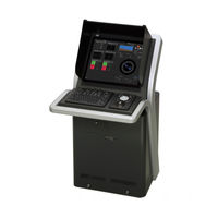
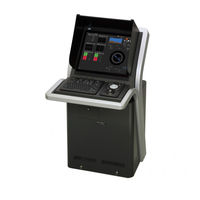
JRC JAN-9202 Installation Manual (100 pages)
MARINE RADAR EQUIPMENT / ECDIS / CONNING /ECDIS/CONNING
Brand:
JRC
| Category:
Marine Radar
| Size: 4.42 MB
Table of Contents
Table of Contents
44
Contents
54
1 Overview
54
Functions
54
Main Functions of the RADAR Mode
54
Main Functions of the ECDIS Mode
55
Features
56
Components
59
2 Installation of Scanner Unit
64
Equipment Cable
64
Cfq-6912
64
Cable End Processing Method
70
Connection to the Display-Unit Side Terminal Block
73
Installation for the Specified Scanner Model
75
NKE-2103 Type Scanner Unit
75
NKE-2254-6HS Type Scanner Unit
77
NKE-1125 Type Scanner Unit
79
NKE-1129 Type Scanner Unit
81
NKE-1130 Type Scanner Unit
83
NKE-1139 Type Scanner Unit
85
NKE-1632 Type Scanner Unit
87
NKE-2632 Type Scanner Unit
89
Installation of Transmitter Receiver
91
NTG-3225 Type Transmitter Receiver Unit
91
NTG-3230 Type Transmitter Receiver Unit
93
Precautions
95
Installation of Scanner Unit
96
Routing Coaxial Cable and Flexible Wave Guide
99
Advertisement
Related Products
JRC JAN-701B -
JRC JAN-901B -
JRC JAN-9201
JRC JAN-7201
JRC JAN-7202
JRC JMR-7210-6X
JRC JMA-3404
JRC JMR-7225-9X3
JRC JMR-7225-7X3
JRC JMR-7230-S3
JRC Categories
Water Filtration Systems
Marine Radar
Marine Equipment
Radio Parts
Receiver
More JRC Manuals
Login
Sign In
OR
Sign in with Facebook
Sign in with Google
Upload manual
Upload from disk
Upload from URL