Sign In
Upload
Manuals
Brands
JRC Manuals
Marine Radar
JMA-3404
JRC JMA-3404 Manuals
Manuals and User Guides for JRC JMA-3404. We have
2
JRC JMA-3404 manuals available for free PDF download: Instruction Manual
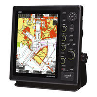
JRC JMA-3404 Instruction Manual (314 pages)
Brand:
JRC
| Category:
Marine Radar
| Size: 27.79 MB
Table of Contents
Precautions before Operation
3
First-Aid Treatments
4
Preface
12
Checking the Supplied Items
12
Before Operation
13
Precautions
17
Warning Label Mounting Point
22
Packing List
24
Equipment Appearance
30
Table of Contents
35
Contents
36
Glossary
44
Chapter 1 INSTALLATION
49
Overview
49
Installation of the Display Unit
50
Selecting the Installation Position
50
Selection of Display Mounting
50
Dimensional Drawing of Display Mounting
51
Examples of Display Mounting
53
Power Cable Installation
57
External Navigational Signal Connection
58
Installation of the Scanner Unit
60
Selecting the Installation Position
60
Lowest Scanner Installation Height
61
Mounting Rack and Mast for the Scanner
62
Scanner and the Surrounding Structural Objects
62
Ensuring View Angle
63
Confirm Mounting Base before Install
65
Connecting the Installation Cable
71
Nke-2043 Scanner (2 Feet)
72
Nke-2063A Scanner (3.9 Feet)
76
Nke-2063Ahs Scanner (3.9 Feet)
79
Nke-2103-4/6 Scanner (4 Feet/6 Feet)
82
Chapter 2 THE BASIC OPERATION
84
Panel and Screen Display Layout
84
Operation Unit
85
Power On/Off
89
Screen Layout
90
Standby Screen
90
Transmission Screen
91
Multi Control Operation
92
Function Overview of Multi Control Menu
94
Chapter 3 ADJUST the RADAR ECHO
95
Change Range
95
Sensitivity Adjustment (Gain)
96
Sea Clutter Suppression (Sea)
97
Rain/Snow Clutter Suppression (Rain)
98
Screen Brilliance (Brill)
99
Chapter 4 VRM and EBL FUNCTION
100
Operation of Vrm, Ebl
100
Example of Vrm Function
100
Example of Ebl Function
101
Chapter 5 VARIOUS FUNCTIONS
102
Parallel Cursor Function
102
Mob Function (man Overboard)
105
Anchor Watch Function
106
Vector Length
108
Radar Trails
109
Setup the Radar Trails Interval
109
Ais Operations
110
Ais List
112
Tt Operations
114
Off-Center Function
119
Mark Function
119
Line Function
122
Ownship Mark Function
125
User Option Keys
127
Mode Function
128
Setting Display Brilliance and Color
130
Cursor Function
131
Radar Echo Setting
132
Pulse Width
133
Ir (Interference Rejection)
133
Target Enhance
134
Process
134
Zoom Mode
134
Video Noise Rejection
135
Video Latitude
135
Tune
136
Marker
137
Ebl Setting
137
Parallel Cursor
138
Vrm Unit
139
Cursor Mode
139
Range Ring
140
Set Own Ship Movement
141
Trails Setting
142
Threshold
143
Time/All Combine
143
Trails Mode
143
Vector
144
Vector Mode
144
Display Own Ship's Vector
144
Own Ship Vector Line Width
145
Offcenter Setting
145
Function Setting
146
Function Enable/Disable
147
Auto Stc/Ftc
147
Trails Interval
148
Antenna Height
148
Save Present State
148
Initialize
148
Ais/Tt
150
Collision Avoidance
150
Function On/Off
154
Cpa Limit
154
Tcpa Limit
154
Cpa Ring
154
Target Number Display
154
Target Number Allocation
155
Tll Target Number Allocation
155
Alr Alarm from Ais
155
Ais Display Target
155
Ais Destination Ship
155
Ais Retrieved Vessel
155
Ais Filter
155
Guard Zone
156
Zone Alarm Level
157
Zone Mode
157
Make Zone
157
Waypoint Display
158
Chart
159
Type
159
Display
160
Symbol
160
Palette
160
Show Extend Data
160
Set Chart Operation
161
Mark Setting
162
Mark Size
162
Mark Color
162
Mark Type
163
Display Mark Color
163
Display Mark Type
163
Mark List
163
Ownship Mark Setting
165
Own Ship Position Mark Size
165
Own Ship Position Mark Color
165
Own Ship Position Mark Type
166
Display Mark Color
166
Display Mark Type
166
Own Ship Position Mark List
166
Line Setting
168
Line Color
168
Line Type
168
Display Line Color
168
Display Line Type
169
Line List
169
Own Track Setting
171
Own Track Record On/Off
171
Own Track Record Display On/Off
171
Own Track Color
172
Own Track Type
172
Own Track Interval
172
Display Own Track Color
172
Display Own Track Type
172
Clear Own Track Color/Type
172
File Operation
173
Save
173
Load
173
Delete
173
Screen Capture
174
Capture Function
175
Set Manual Key
175
Interval
175
Timed Tx
176
Tx Time
176
Standby Time
177
Tll Tx "User2
177
Certification Information
177
Chapter 6 OPTION and OTHER FUNCTIONS
178
Nmea Cable
178
External Monitor Output
181
Rectifier Unit
181
Chapter 7 INITIAL SETTINGS
182
Language Selection
183
Bearing Adjustment
183
Range Adjustment
184
Tuning Adjustment
185
Antenna Height Set up
185
Communication Port Setup
186
Baud Rate
187
Rx Sentence
187
Rx Port
188
Tx Port
188
Tx Data Format
189
Target Information Tx
189
I/F Device
190
Heading Equipment
191
Manual Heading
191
Speed Equipment
191
Manual Speed
191
Magnetic Compass
191
Jrc Gps
192
Nmea Version
192
Gps Setting
193
Beacon Setting
197
Sbas Setting
198
Gps Status Display
199
Loran Setting
199
Chapter 8 DETAIL PERFORMANCE SETTINGS
200
Radar Echo
200
Noise Level
201
Main Bang Suppression
201
Target Enhance Level
202
Gain
202
Sea
202
Rain
203
Trails
204
Trails Suppression Distance
204
Max Interval
205
Range Limit
205
Target Tracking (Tt)
206
Scanner
207
Slope Correction
208
Pulse Repetition Frequency Fine Tuning (Prf Fine Tuning)
208
Stagger Trigger
208
Scanner Rotation Speed
208
Prf Output Mode
208
Safety Switch
208
Tune Peak Adjustment
209
Tune Indicator Level
209
Stop Antenna in the Specified Direction
209
Ice Class Standby Mode
209
Control
210
Multi Control Menu Time out
210
Cross Key Gain
210
Multi Control
211
Gain Control/Sea Control/Rain Control
211
Buzzer
212
Maintenance
213
Reset Partial
214
Master Reset
215
System Time Clear
215
Scanner Time Clear
216
Internal Setting
217
Usb Format
219
System Setting
220
Master/Slave/Demo
221
Own Outline
221
Barge Outline
221
Bearing Marker
221
Operation Numeric Display
221
Unit
222
Move Own Ship
222
Range
223
Display Screen
224
Standby Numeric Display
225
Display Color
225
Operation Numeric Display
226
Wide Screen
227
Time
227
Radar Echo Color
228
Error Alarm Mask
229
Scanner
230
Display Unit
230
Connection Device
231
Rx Data
231
Network
232
Network Function
233
Ip Address
233
Radar Echo Transmission Setting
233
Can
235
Can out
235
Can
236
Chapter 9 TRUE or FALSE ECHOS on DISPLAY
237
Radar Wave with the Horizon
237
Reflection from Target
238
Sea Clutter and Rain and Snow Clutter
239
Sea Clutter
239
Rain and Snow Clutter
239
Coping with Sea Clutter and Rain and Snow Clutter
239
False Echoes
240
Shadow
240
Side Lobe Effect
240
False Echo by Secondary Reflection
240
False Echo by Multiple Reflection
241
Second Time Echoes
241
Radar Interference
241
Display of Radar Transponder (Sart)
242
Chapter 10 MAINTENANCE and CHECK
243
Routine Maintenance
243
Maintenance of each Unit
244
Scanner Unit Nke-2043, 2063A/Ahs, 2103-4/4Hs/6/6Hs
244
Display Ncd-2364
246
Performance Check
247
Test-System Information
248
System Information
248
System Time
248
Scanner Information
249
Hardware Information
249
Error Log
249
Line Monitor
249
Self Test
250
Software Update
251
Replacement of Major Parts
252
Parts Required for Periodic Replacement
253
Fault Finding
254
Alarms and Other Display Lists
254
Trouble Shooting
259
Special Parts
259
Circuit Block to be Repaired
260
Chapter 11 AFTER-SALE SERVICE
262
Keeping Period of Maintenance Parts
262
When You Request for Repair
262
Recommended Maintenance
262
Radar Failure Check List
263
Chapter 12 DISPOSAL
264
Disposal of the Unit
264
Disposal of Used Magnetron
264
China Rohs
264
Chapter 13 SPECIFICATIONS
265
Scanner Dimension
266
Nke-2043
266
Nke-2063A/Ahs
267
Nke-2103-4/4Hs
268
Nke-2103-6/6Hs
269
Display Dimension
270
Ncd-2364
270
Equipment Outline
271
Configulation
271
Feature
271
Radar Model
271
General Specifications
272
Scanner
274
Scanner (Nke-2043) Specification
274
Scanner (Nke-2063A/Ahs) Specification
275
Scanner (Nke-2103-4/6/4Hs/6Hs) Specification
276
Display
277
Integrated Display Unit (Ncd-2364)
277
Operational Part
279
Ais Function (Standard Built In)
280
Tt Function (Standard Built In)
280
Input/ Output Signal
281
Input Enable Signal
281
Output Possible Signal
282
Standard Configuration
282
Option Cable
282
Appendix
290
Jma-3404 Interconnection Diagram
290
Jma-3406/Hs Interconnection Diagram
291
Jma-3411-4/4Hs/6/6Hs Interconnection Diagram
292
Menu Function List
294
Declaration of Conformity
311
Advertisement
JRC JMA-3404 Instruction Manual (307 pages)
MARINE RADAR EQUIPMENT
Brand:
JRC
| Category:
Marine Radar
| Size: 22.12 MB
Table of Contents
First-Aid Treatments
4
Preface
12
Checking the Supplied Items
12
Before Operation
13
Precautions
17
Warning Label Mounting Point
22
Packing List
24
Equipment Appearance
30
Table of Contents
35
Contents
36
Glossary
44
Chapter 1 INSTALLATION
49
Overview
49
Installation of the Display Unit
50
Selecting the Installation Position
50
Selection of Display Mounting
50
Dimensional Drawing of Display Mounting
51
Examples of Display Mounting
53
Power Cable Installation
57
External Navigational Signal Connection
58
Installation of the Scanner Unit
60
Selecting the Installation Position
60
Lowest Scanner Installation Height
61
Mounting Rack and Mast for the Scanner
62
Ensuring View Angle
63
Confirm Mounting Base before Install
65
Connecting the Installation Cable
70
Nke-2043 Scanner (2 Feet)
71
Nke-2063A Scanner (3.9 Feet)
75
Nke-2063Ahs Scanner (3.9 Feet)
77
Nke-2103-4/6 Scanner (4 Feet/6 Feet)
79
Chapter 2 THE BASIC OPERATION
81
Panel and Screen Display Layout
81
Operation Unit
82
Power On/Off
86
Screen Layout
87
Standby Screen
87
Transmission Screen
88
Multi Control Operation
89
Function Overview of Multi Control Menu
91
Chapter 3 ADJUST the RADAR ECHO
92
Change Range
92
Sensitivity Adjustment (Gain)
92
Sea Clutter Suppression (Sea)
94
Rain/Snow Clutter Suppression (Rain)
95
Screen Brilliance (Brill)
96
Chapter 4 VRM and EBL FUNCTION
98
Operation of Vrm, Ebl
98
Example of Vrm Function
98
Example of Ebl Function
99
Chapter 5 VARIOUS FUNCTIONS
100
Parallel Cursor Function
100
Mob Function (man Overboard)
103
Anchor Watch Function
104
Vector Length
106
Radar Trails
107
Setup the Radar Trails Interval
107
Ais Operations
108
Ais List
110
Tt Operations
112
Off-Center Function
116
Mark Function
117
Line Function
120
Ownship Mark Function
123
User Option Keys
125
Mode Function
126
Setting Display Brilliance and Color
128
Cursor Function
129
Radar Echo Setting
130
Pulse Width
131
Ir (Interference Rejection)
131
Target Enhance
132
Process
132
Zoom Mode
132
Video Noise Rejection
133
Video Latitude
133
Tune
134
Marker
135
Ebl Setting
135
Parallel Cursor
136
Vrm Unit
137
Cursor Mode
137
Range Ring
138
Set Own Ship Movement
139
Trails Setting
140
Threshold
141
Time/All Combine
141
Trails Mode
141
Vector
142
Vector Mode
143
Display Own Ship's Vector
143
Own Ship Vector Line Width
143
Offcenter Setting
144
Function Setting
145
Function Enable/Disable
146
Auto Stc/Ftc
146
Trails Interval
147
Antenna Height
147
Save Present State
147
Initialize
147
Ais/Tt
148
Function On/Off
149
Cpa Limit
149
Tcpa Limit
149
Cpa Ring
149
Target Number Display
149
Target Number Allocation
150
Tll Target Number Allocation
150
Alr Alarm from Ais
150
Ais Display Target
150
Ais Destination Ship
150
Ais Retrieved Vessel
150
Ais Filter
150
Guard Zone
151
Zone Alarm Level
152
Zone Mode
152
Make Zone
152
Waypoint Display
153
Chart
154
Type
154
Display
155
Symbol
155
Palette
155
Show Extend Data
155
Set Chart Operation
156
Mark Setting
157
Mark Size
157
Mark Color
158
Mark Type
158
Display Mark Color
158
Display Mark Type
158
Mark List
158
Ownship Mark Setting
160
Own Ship Position Mark Size
160
Own Ship Position Mark Color
161
Own Ship Position Mark Type
161
Display Mark Color
161
Display Mark Type
161
Own Ship Position Mark List
161
Line Setting
163
Line Color
163
Line Type
163
Display Line Color
164
Display Line Type
164
Line List
164
Own Track Setting
166
Own Track Record On/Off
166
Own Track Record Display On/Off
166
Own Track Color
167
Own Track Type
167
Own Track Interval
167
Display Own Track Color
167
Display Own Track Type
167
Clear Own Track Color/Type
167
File Operation
168
Save
168
Load
168
Delete
169
Screen Capture
169
Capture Function
170
Set Manual Key
170
Interval
170
Timed Tx
171
Tx Time
171
Standby Time
172
Tll Tx "User2
172
Certification Information
172
Chapter 6 OPTION and OTHER FUNCTIONS
173
Nmea Cable
173
External Monitor Output
176
Rectifier Unit
176
Chapter 7 INITIAL SETTINGS
177
Language Selection
178
Bearing Adjustment
178
Range Adjustment
178
Tuning Adjustment
179
Antenna Height Set up
180
Communication Port Setup
181
Baud Rate
182
Rx Sentence
182
Rx Port
183
Tx Port
183
Tx Data Format
184
Target Information Tx
184
I/F Device
185
Heading Equipment
186
Manual Heading
186
Speed Equipment
186
Manual Speed
186
Magnetic Compass
186
Jrc Gps
187
Nmea Version
188
Gps Setting
189
Beacon Setting
193
Sbas Setting
194
Gps Status Display
195
Loran Setting
195
Chapter 8 DETAIL PERFORMANCE SETTINGS
196
Radar Echo
196
Noise Level
197
Main Bang Suppression
197
Target Enhance Level
198
Gain
198
Sea
198
Rain
199
Trails
200
Trails Suppression Distance
200
Max Interval
201
Range Limit
201
Scanner
203
Slope Correction
204
Pulse Repetition Frequency Fine Tuning (Prf Fine Tuning)
204
Stagger Trigger
204
Scanner Rotation Speed
204
Prf Output Mode
204
Safety Switch
205
Tune Peak Adjustment
205
Tune Indicator Level
205
Stop Antenna in the Specified Direction
205
Ice Class Standby Mode
206
Control
206
Multi Control Menu Time out
206
Cross Key Gain
207
Multi Control
207
Gain Control/Sea Control/Rain Control
207
Buzzer
208
Maintenance
209
Reset Partial
210
Reset All
211
System Time Clear
211
Scanner Time Clear
212
Internal Setting
213
Usb Format
215
System Setting
216
Master/Slave/Demo
217
Own Outline
217
Barge Outline
217
Bearing Marker
217
Operation Numeric Display
217
Unit
218
Move Own Ship
218
Range
219
Display Screen
220
Standby Numeric Display
221
Display Color
221
Operation Numeric Display
222
Wide Screen
223
Time
223
Radar Echo Color
224
Error Alarm Mask
225
Scanner
226
Display Unit
226
Connection Device
227
Rx Data
227
Network
228
Network Function
229
Ip Address
229
Radar Echo Transmission Setting
229
Nmea2000
231
Nmea2000 out
232
Nmea2000
232
Chapter 9 MAINTENANCE and CHECK
233
Routine Maintenance
233
Maintenance of each Unit
234
Scanner Unit Nke-2043, 2063A/Ahs, 2103-4/4Hs/6/6Hs
234
Display Ncd-2364
236
Performance Check
237
Test-System Information
238
System Information
238
System Time
238
Scanner Information
239
Hardware Information
239
Error Log
239
Line Monitor
239
Self Test
240
Software Update
242
Replacement of Major Parts
243
Parts Required for Periodic Replacement
244
Fault Finding
245
Alarms and Other Display Lists
245
Trouble Shooting
250
Special Parts
250
Circuit Block to be Repaired
251
Chapter 10 AFTER-SALE SERVICE
254
Keeping Period of Maintenance Parts
254
When You Request for Repair
254
Recommended Maintenance
254
Radar Failure Check List
255
Chapter 11 DISPOSAL
256
Disposal of the Unit
256
Disposal of Used Magnetron
256
China Rohs
256
Chapter 12 SPECIFICATIONS
257
Display Dimension
262
Ncd-2364
262
Equipment Outline
263
Configulation
263
Feature
263
Radar Model
263
General Specifications
264
Scanner
266
Scanner (Nke-2043) Specification
266
Scanner (Nke-2063A/Ahs) Specification
267
Scanner (Nke-2103-4/6/4Hs/6Hs) Specification
268
Display
269
Integrated Display Unit (Ncd-2364)
269
Operational Part
271
Ais Function (Standard Built In)
272
Tt Function (Standard Built In)
272
Input/ Output Signal
273
Input Enable Signal
273
Output Possible Signal
275
Standard Configuration
275
Option Cable
275
Appendix
285
Advertisement
Related Products
JRC JMA-3400 Series
JRC JMA-3406
JRC JMA-3411-4
JRC JMA-3411-6
JRC JMA-3910-6
JRC JMA-3316
JRC JMA-3316HS
JRC JMA-3340-6
JRC JMA-3340-6HS
JRC JMA-3810
JRC Categories
Water Filtration Systems
Marine Radar
Marine Equipment
Radio Parts
Receiver
More JRC Manuals
Login
Sign In
OR
Sign in with Facebook
Sign in with Google
Upload manual
Upload from disk
Upload from URL