Sign In
Upload
Manuals
Brands
Intel Manuals
Server Board
S875WP1-E
Intel S875WP1-E Manuals
Manuals and User Guides for Intel S875WP1-E. We have
2
Intel S875WP1-E manuals available for free PDF download: Specification, Product Manual
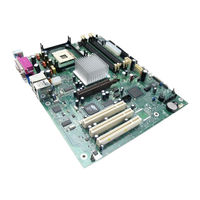
Intel S875WP1-E Product Manual (112 pages)
Product Guide
Brand:
Intel
| Category:
Server Board
| Size: 0 MB
Table of Contents
Important Safety Instructions
2
Table of Contents
3
1 Server Board Features
9
Table 1. Server Board Features
9
Server Board Connector and Component Locations
11
Figure 1. Server Board Components
11
Back Panel Connectors
12
Figure 2. Back Panel Connectors
12
Figure 3. Front Panel Connectors
12
Front Panel Connectors
12
Processor
13
Memory
13
Table 2. Supported Processors
13
Intel 875P Chipset
14
Intel 82875P Memory Controller Hub (MCH)
14
Intel 82801EB I/O Controller Hub (ICH5-R)
15
Intel 82802AC Firmware Hub (FWH)
15
Video
15
AGP Connector
16
ATA Rage XL Video Controller
16
Table 3. Video Modes
16
Video Modes
16
Video Memory Interface
17
Super I/O
17
Floppy Drive Controller
18
Keyboard and Mouse Connectors
18
Parallel Port
18
Serial Port
18
Usb
19
High-Speed USB 2.0 Support
19
Legacy USB Support
19
PCI I/O Subsystem
20
32-Bit, 33-Mhz PCI Subsystem
20
Table 4. PCI Bus Characteristics
20
Device Ids (IDSEL)
21
Data Storage
21
Serial ATA (SATA)
21
Table 5. PCI Bus Configuration Ids
21
IDE Interfaces
22
SCSI Hard Drive Activity LED Connector
22
Network Interface Controller (NIC)
23
NIC Connector and Status Leds
23
Table 6. 10/100 Ethernet LAN Connector Leds
23
Power Management
24
Software Support through ACPI
24
Table 7. 10/100/1000 Gigabit Ethernet LAN Connector Leds
24
Table 8. Effects of Pressing the Power Switch under ACPI
25
Table 9. Wake-Up Devices and Events
26
Wake-Up Devices and Events
26
Hardware Support
27
Fan Connectors
28
Power Connector
28
Table 10. Fan Connector Function/Operation
28
Figure 4. Location of the Standby Power Indicator LED CR7J1
29
Instantly Available PC Technology
29
Hardware Management and Monitoring
30
Chassis Intrusion and Detection
30
Password Security
31
Table 11. Supervisor and User Password Functions
31
Real-Time Clock, CMOS SRAM, and Battery
32
Recovering the CMOS
32
Figure 5. Location of Clear CMOS Jumper
32
Bios
33
IDE Auto Configuration
33
PCI Auto Configuration
33
BIOS Updates
34
Language Support
34
Boot Options
35
CD-ROM and Network Boot
35
Custom Splash Screen
35
Recovering BIOS Data
35
Booting Without Attached Devices
36
Fast Booting Systems with Intel ® Rapid BIOS Boot
36
Intel Rapid BIOS Boot
36
System Management BIOS (SMBIOS)
37
2 Server Board Installation and Upgrades
39
Tools and Supplies Needed
39
Before You Begin
39
Emissions Disclaimer
39
Warnings and Cautions
39
Installing the I/O Shield
41
Figure 6. Installing the I/O Shield
41
Installing Chassis Standoffs
42
Intel Server Chassis SC5200
42
Figure 7. Installing Chassis Standoffs in the SC5200 Chassis
42
Intel Server Chassis SC5250-E
43
Figure 8. Installing Chassis Standoffs in the SC5250-E Chassis
43
Installing the Server Board
44
Placing the Server Board into the Chassis
44
Attaching the Server Board
44
Figure 9. Placing the Server Board into the Chassis
44
Installing the Processor
45
Figure 10. Attaching the Server Board
45
Figure 11. Installing the Processor in the Processor Socket
45
Figure 12. Attaching the Heat Sink to the Processor
46
Figure 13. Attaching the Fan Heat Sink Clips to the Processor Socket
47
Figure 14. Attaching the Fan Heat Sink Clips to the Processor Socket
47
Removing the Processor
48
Figure 15. Connecting the Processor Fan Cable to the Processor Fan Connector
48
Installing and Removing Memory
49
DIMM Installation Guidelines
49
Installing Dimms
50
Figure 16. DIMM Socket Locations
50
Removing Dimms
51
Installing and Removing an AGP Card
51
Installing an AGP Card
52
Removing the AGP Card
52
Figure 17. Installing the AGP Card
52
Connecting the IDE Cable
53
Figure 18. Connecting the IDE Cable
53
Connecting the Serial ATA Cable (Optional)
54
Figure 19. Connecting the SATA Cable
54
Connecting Internal Headers
55
Connecting the Front Panel Header
55
Figure 20. Location of Internal Headers
55
Table 12. Front Panel Header (J7J1)
55
Connecting the USB 2.0 Header
56
Table 13. USB 2.0 Header (J7E1)
56
Connecting Hardware Control and Power Cables
57
Figure 21. Location of the Fan Headers and Power Connectors
57
Chassis Intrusion
58
Connecting Fans
58
Connecting Power Cables
58
Setting the BIOS Configuration Jumper
58
Figure 22. BIOS Configuration Jumper Block Location
58
Clearing Passwords
59
Table 14. Jumper Settings for the BIOS Setup Program Modes (J8J2)
59
Replacing the Battery
60
Figure 23. Removing the Battery
62
3 Configuration Software and Utilities
63
Updating the BIOS with the Intel Flash Memory Update Utility
63
Obtaining the BIOS Update File
63
Recording the Current BIOS Settings
64
Creating Bootable Media
64
Creating a BIOS Update Media
65
Updating the BIOS
66
Recovering the BIOS
67
Using the Setup Program
68
BIOS Setup Program Modes
68
Table 15. BIOS Setup Program Menu Bar
68
Maintenance Menu
69
Table 16. BIOS Setup Program Function Keys
69
Table 17. Maintenance Menu
69
Main Menu
70
Table 18. Main Menu
70
Advanced Menu
71
Table 19. Advanced Menu
71
PCI Configuration Submenu
72
Table 20. PCI Configuration Submenu
72
Boot Configuration Submenu
73
Table 21. Boot Configuration Submenu
73
Peripheral Configuration Submenu
74
Table 22. Peripheral Configuration Submenu
74
Drive Configuration Submenu
76
Table 23. Drive Configuration Submenu
76
Table 24. Primary/Secondary/Sata-0/SATA-1 Master/Slave Submenus
78
Floppy Configuration Submenu
79
Table 25. Floppy Configuration Submenu
79
Event Log Configuration Submenu
80
Table 26. Event Log Configuration Submenu
80
Table 27. Video Configuration Submenu
81
Video Configuration Submenu
81
Table 28. USB Configuration Submenu
82
USB Configuration Submenu
82
Chipset Configuration Submenu
83
Table 29. Chipset Configuration Submenu
83
Fan Control Configuration Submenu
85
Table 30. Fan Control Configuration Submenu
85
Hardware Monitoring Submenu
86
Table 31. Hardware Monitoring Submenu
86
Remote Access Configuration Submenu
87
Table 32. Remote Access Configuration Submenu
87
Security Menu
88
Table 33. Security Menu
88
Power Menu
89
ACPI Submenu
89
Table 34. Power Menu
89
Table 35. ACPI Submenu
89
Boot Menu
90
Table 36. Boot Menu
90
Boot Device Priority Submenu
91
Hard Disk Drives Submenu
91
Table 37. Boot Device Priority Submenu
91
Table 38. Hard Disk Drives Submenu
91
ATAPI CDROM Drives Submenu
92
Removable Devices Submenu
92
Table 39. Removable Devices Submenu
92
Table 40. ATAPI CDROM Drives Submenu
92
Exit Menu
93
Table 41. Exit Menu
93
4 Solving BIOS Problems
95
BIOS Beep Codes
95
Table 42. Beep Codes
95
BIOS Error Messages
96
Table 43. BIOS Error Messages
96
5 Getting Help
99
World Wide Web
99
Telephone
99
6 Technical Reference
101
Server Board Connectors
101
Baseboard Connectors
102
Figure 24. Power, Fan, and Chassis Intrusion Connectors
102
Power, Fan, Chassis Intrusion Connectors
102
Add-In Board and Peripheral Interface Connectors
103
Figure 25. Add-In Board and Peripheral Interface Connectors
103
Server Board Resources
104
Memory Map
104
DMA Channels
104
Table 44. System Memory Map
104
Table 45. DMA Channels
104
I/O Map
105
Table 46. I/O Map
105
Interrupts
106
Table 47. Interrupts
106
7 Regulatory and Integration Information
107
Product Regulatory Compliance
107
Product Safety Compliance
107
Product EMC Compliance
107
Product Regulatory Compliance Markings
108
Table 48. Product Certification Markings
108
Electromagnetic Compatibility Notices
109
Fcc (Usa)
109
Industry Canada (Ices-003)
110
Europe (CE Declaration of Conformity)
110
Taiwan Declaration of Conformity
110
Korean RRL Compliance
110
Australia / New Zealand
110
Installation Precautions
111
Installation Requirements
111
Prevent Power Supply Overload
111
Place Battery Marking
112
Use Only for Intended Applications
112
Advertisement
Intel S875WP1-E Specification (117 pages)
Product Specification
Brand:
Intel
| Category:
Server Board
| Size: 0 MB
Table of Contents
Revision History
2
Table of Contents
4
1 Introduction
13
2 Server Board Overview
14
S875WP1-E Feature Set
14
Figure 1. Intel Server Board S875WP1-E Diagram
16
3 Functional Architecture
17
Processor and Memory Subsystem
17
Processor Support
17
Table 1. Processor Support Matrix
17
Memory Subsystem
18
Table 2. Supported Memory Configurations
18
Memory Configurations
19
Table 3. Supported System Bus Frequency and Memory Speed Combinations
19
Table 4. Characteristics of Dual/Single Channel Configuration With/Without Dynamic Mode
20
Figure 2. Examples of Dual Channel Configuration with Dynamic Mode
21
Figure 3. Example of Dual Channel Configuration Without Dynamic Mode
22
Figure 4. Examples of Single Channel Configuration with Dynamic Mode
23
Figure 5. Examples of Single Channel Configuration Without Dynamic Mode
24
Intel 875P Chipset
25
Figure 6. Intel 875P Chipset Block Diagram
25
Agp
26
Usb
26
Figure 7. USB Port Configuration
27
IDE Interfaces
27
Intel 82802AC 8 Megabit Firmware Hub (FWH)
29
Real-Time Clock, CMOS SRAM, and Battery
29
Serial ATA (SATA) Support
30
SATA Interfaces
30
SATA RAID with ICH5-R Controller
30
SATA RAID with Promise Technology PDC20319
31
I/O Controller
32
Serial Ports
32
Parallel Port
32
Diskette Drive Controller
33
Keyboard and Mouse Interface
33
Hardware Management Subsystem
34
Hardware Monitoring and Fan Control ASIC
34
Fan Monitoring
34
Chassis Intrusion and Detection
35
Power Management
35
Advanced Configuration and Power Interface (ACPI)
35
Hardware Support
35
Table 5. Effects of Pressing the Power Switch
36
Table 6. Power States and Targeted System Power
36
Table 7. Wake-Up Devices and Events
37
Table 8. Fan Connector Function/Operation
39
Standby Power (+5 V) Indicator LED
40
Figure 8. Location of the Standby Power Indicator LED (CR7J1)
41
Table 9. PCI Bus Characteristics
42
Clock Generation and Distribution
42
PCI I/O Subsystem
42
Bit, 33-Mhz PCI Subsystem
43
Table 10. PCI Bus Configuration Ids
43
Video Controller
43
Table 11. Video Modes
44
Network Interface Controller (NIC) Subsystem
45
Figure 9. LAN Connector LED Locations
46
RJ-45 LAN Connectors with Integrated Leds
46
Table 12. 10/100 Ethernet LAN Connector Leds
46
Table 13. 10/100/1000 LAN Connector LED States
46
DMA Channels
47
Table 14. System Memory Map
47
Table 15. I/O Map
47
PCI Configuration Space Map
47
Interrupts
47
Table 16. DMA Channels
48
Table 17. PCI Configuration Space Map
49
Table 18. Interrupts
50
Table 19. PCI Interrupt Routing Map
51
5 Connectors and Jumper Blocks
52
Table 20. Power Connector Pin-Out (J2J2)
52
Table 21. 12V CPU Power Connector (J4C1)
52
Power Connectors
52
Table 22. Auxiliary Power Connector (J4J1)
53
Table 23. PCI Bus Connectors
53
Table 24. AGP Connector
54
Table 25. High-Density Front Panel 34-Pin Header Pin out (J7J1)
55
Front Panel Connector
55
Table 26. VGA Connector Pin-Out (J3A1)
56
Table 27. Magjack3 Connector (Dual USB + RJ45, Gbe) Pin out (JA4A1)
56
NIC /USB Connector
56
Table 28. Magjack3 Connector (Dual USB + RJ45, 10/100) Pin out (JA5A1)
57
Table 29. SATA 7-Pin Connectors Pin out (J9E1, J9F1, J9G1, J9H1, J9H2, J9J2)
57
Table 30. ICH5-R IDE 40-Pin Connector Pin out (J5J1, J6J1)
58
ICH5-R IDE Connectors
58
Table 31. Front Panel USB Connector Pin-Out (J7E1)
58
Table 32. 34-Pin Floppy Connector Pin out (J3J1)
59
Table 33. 9-Pin Serial a Port Pin out (J2A1)
59
Serial Port Connector
59
Table 34. 10-Pin Header Serial B Port Pin out (J6J4)
60
Table 35. Keyboard /Mouse PS/2 Connector Pin out (J1A1)
60
Miscellaneous Headers
61
Table 36. Three-Pin Fan Headers Pin-Out
61
Table 37. BIOS Setup Configuration Jumper Settings (J8J2)
61
System Recovery and Update Jumper
61
Table 38. Clear CMOS Jumper Settings (J8G1)
62
BIOS Flash Memory Organization
63
Resource Configuration
63
PCI Autoconfiguration
63
PCI IDE Support
64
System Management BIOS (SMBIOS)
64
6 BIOS Features
64
Legacy USB Support
65
BIOS Updates
66
Language Support
66
Custom Splash Screen
66
Recovering BIOS Data
67
Boot Options
67
CD-ROM and Network Boot
67
Booting Without Attached Devices
68
Intel Rapid BIOS Boot
69
BIOS Security Features
69
Table 39. Supervisor and User Password Functions
70
7 BIOS Setup Program
71
Table 40. BIOS Setup Program Menu Bar
71
Maintenance Menu
71
Table 41. BIOS Setup Program Function Keys
71
Table 42. Maintenance Menu
72
Table 43. Main Menu
72
Table 44. Advanced Menu
74
Table 45. PCI Configuration Submenu
75
Table 46. Boot Configuration Submenu
76
Table 47. Peripheral Configuration Submenu
77
Table 48. Drive Configuration Submenu
79
Table 49. Primary/Secondary Master/Slave Submenus
81
Table 50. Floppy Configuration Submenu
82
Table 51. Event Log Configuration Submenu
83
Table 52. Video Configuration Submenu
84
Table 53. USB Configuration Submenu
85
Table 54. Chipset Configuration Submenu
86
Table 55. Fan Control Configuration Submenu
88
Table 56. Hardware Monitoring Submenu
89
Table 57. Remote Access Configuration Submenu
90
Table 58. Security Menu
91
Table 59. Power Menu
92
Table 60. ACPI Submenu
92
Table 61. Boot Menu
93
Table 62. Boot Device Priority Submenu
94
Table 63. Hard Disk Drives Submenu
95
Table 64. Removable Devices Submenu
96
Table 65. ATAPI CDROM Drives Submenu
97
Table 66. Exit Menu
97
8 Error Reporting and Handling
98
Error Sources and Types
98
PCI Bus Errors
98
Processor Bus Errors
98
Single-Bit ECC Error Throttling Prevention
99
Memory Bus Errors
99
BIOS Error Messages, POST Codes, and BIOS Beep Codes
99
Table 67. BIOS Error Messages
100
Port 80H POST Codes
101
Table 68. Uncompressed INIT Code Checkpoints
101
Table 69 Boot Block Recovery Code Checkpoints
102
Table 70. Runtime Code Uncompressed in F000 Shadow RAM
102
Table 71. BIOS Beep Codes
105
Table 72. Bus Initialization Checkpoints
106
Table 73. Upper Nibble High Byte Functions
106
Table 74. Lower Nibble High Byte Functions
106
Table 75. Absolute Maximum Ratings
107
Table 76. S875WP1-E Power Budget
107
Product Regulatory Compliance
108
Product Safety Compliance
108
9 General Specifications
108
Product EMC Compliance
108
Product Regulatory Compliance Markings
109
Electromagnetic Compatibility Notices
109
Fcc (Usa)
109
Industry Canada (Ices-003)
110
Europe (CE Declaration of Conformity)
110
Taiwan Declaration of Conformity
110
Korean RRL Compliance
111
Australia / New Zealand
111
Replacing the Back-Up Battery
111
Calculated Mean Time between Failures (MTBF)
112
Mechanical Specifications
112
Figure 10. S875WP1-E Server Board Mechanical Drawing
113
Figure 11. Intel Server Board S875WP1-E I/O Shield Drawing
114
Advertisement
Related Products
Intel S875WP1LX
Intel S815EBM1 - Server Board Motherboard
Intel S845WD11U
Intel S845WD1H
Intel S845WD1-E - Server Board Motherboard
Intel S3420GPRX
Intel SE7230NH1LX
Intel SE7221BK1LX
Intel SE7320VP2D2
Intel S1200V3RP
Intel Categories
Motherboard
Computer Hardware
Server
Desktop
Server Board
More Intel Manuals
Login
Sign In
OR
Sign in with Facebook
Sign in with Google
Upload manual
Upload from disk
Upload from URL