Sign In
Upload
Manuals
Brands
Hitachi Manuals
Inverter
WJ Series
Hitachi WJ Series Manuals
Manuals and User Guides for Hitachi WJ Series. We have
1
Hitachi WJ Series manual available for free PDF download: User Manual
Hitachi WJ Series User Manual (494 pages)
Brand:
Hitachi
| Category:
Inverter
| Size: 9.61 MB
Table of Contents
Chapter 2 Outline of this User' S Guide/Procedure for Operation
39
Table of Contents
39
Before Reading this Guide
40
Overview of each Chapter
41
Procedure for Operation (Flowchart)
43
When Installing a New Inverter
43
When Replacing WJ200 (Old Model) with WJ-C1
45
Chapter 3 3 Main Body of the Product
47
Checking the Product and the Included Items
48
Model of the Product and Specification Label
49
Appearance of the Product and Part Name
50
Appearance of each Model
50
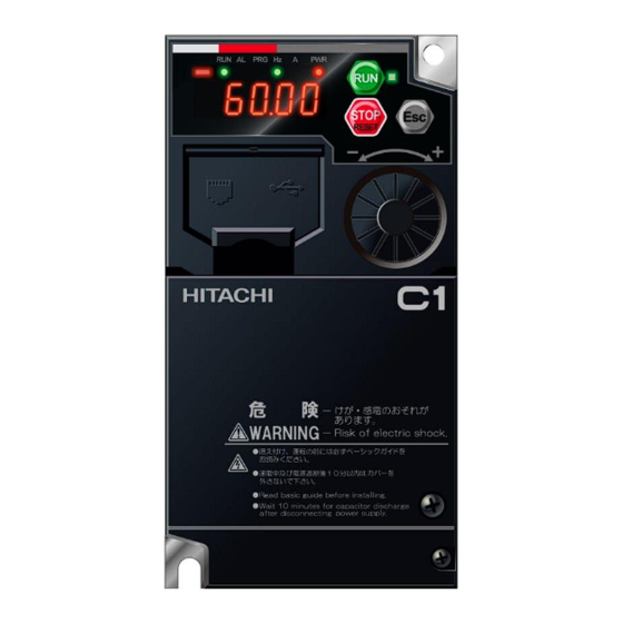
Part Names and Descriptions on the Front of the Product
53
Connecting Remote Operator
54
Chapter 5 5 Wire Connection
61
Remove the Terminal Block Cover
62
Main Circuit Terminal
64
Configuration of Main Circuit Terminal
64
Wiring the Power Supply and Motor
65
Arrangement of Main Circuit Terminal Block
69
Applicable Peripheral Device
71
Overview of Applicable Peripheral Devices
71
Recommended Wire Diameter, Wiring Equipment, Crimp Terminal
72
Applicable Breaker
74
Wiring of DC Link Choke (DCL)
76
Wiring of Braking Resistor and Regenerative Braking Unit
77
Control Circuit Terminal
79
Configuration of Control Circuit Terminal
79
Recommended Wire Diameter and Wiring Method for Control Circuit Terminals
85
Switching Sink/Source Logic and Connecting External Power Supply/Programmable Controller
87
Chapter 7 7 Keypad and Related Functions
95
Name and Content of each Part
96
Key Operation System
98
Example of Parameter Setting Key Operation
99
Functions Related to Keypad
102
Restrict Display Parameter
102
Initialize the Parameters
104
Prohibit Parameter Changes
106
Protecting Data with Passwords
107
Setting the Initial Keypad Display
109
Automatic Registration of Changed Parameter History
110
Display Lock [DISP] Function
111
Remote Operator Functions
112
Chapter 8 Mandatory Setting for Motor Drive and Test Run
113
Overview of Mandatory Setting Items
114
Changing the Load Rating of the Inverter
115
Setting the Motor Specification Label Data to Parameters
118
Setting Electronic Thermal for the Motor
120
Setting Motor Constant
126
Changing the Operation Mode of the Inverter
128
Test Run
129
Test Run by Connecting Only the Motor
129
Perform a Test Run with a Machine Load
133
Carrying out Motor Auto-Tuning
134
Procedure for Auto-Tuning of an Induction Motor
134
Chapter 9 9 Inverter Functions
139
Types of RUN Command
143
Operation by RUN Key on the Keypad
144
Operation by Forward/Reverse Input Terminals
145
Operation by Pushbutton (Momentary Switch) Input
146
Operation by Modbus-RTU Communication (RS485 Communication)
147
Operation by Communication Option Board
148
Temporarily Changing RUN Command Input Source
149
Disabling the STOP/RESET Key on the Keypad
150
Resetting an Alarm
151
Selecting Frequency Command
152
Types of Frequency Command
152
Setting Frequency Command by Keypad
154
Setting Frequency Command by Analog Inputs (Voltage/Current)
155
Setting Frequency Command by Multi-Speed Operation Function
158
Setting Frequency Command for Jogging and Inching Operation
161
Setting Frequency Command by Modbus-RTU Communication (RS485 Communication)
162
Setting Frequency Command by Communication Option Board
163
Setting Frequency Command by Pulse Input
164
Setting Frequency Command by Program Operation Function Ezsq
165
Setting Frequency Command by PID Control
166
Setting Frequency Command by Calculation Operation
167
Temporarily Adding a Set Value to the Frequency Command
168
Increasing/Decreasing Frequency Command by Remote Control
169
Temporarily Changing the Frequency Command Input Source
172
Setting Frequency Command on Frequency Monitor
173
Using Motor Acceleration/Deceleration Function
174
Changing the Acceleration/Deceleration Time
174
Stopping Acceleration/Deceleration
177
Changing the Acceleration/Deceleration Pattern
178
Making the Frequency Instantaneously Follow the Command
180
Limiting Frequency Command/Run Command
181
Limiting Frequency Command
181
Limiting RUN Command Direction
182
Limiting Rotation Output Direction
183
Disabling Output until RUN Command Permission
184
Selecting Control Mode for the Motor and Load
185
Selection of Control Mode
185
Driving with V/F Control
186
Using Torque Boost Function
189
Driving with Energy-Saving Mode
191
Driving with V/F Control with Encoder
192
Stabilizing Motor Hunting
194
Driving with Sensorless Vector Control
195
Using Encoder Feedback
198
Speed/Torque Control According to Load
203
Speed Control and Torque Control
203
Driving with Limited Torque
204
Driving by Torque Reference
207
Driving with Torque Bias
208
Selecting Start/Stop Modes
209
Starting with Gradually Increasing Voltage
209
Starting with DC Braking
210
Starting with Frequency Matching
211
Starting with Active Frequency Matching
212
Starting after Trip Reset or Power-On
216
Starting after Free Run Stop
217
Selecting Stop Operation
218
Stopping with DC Braking
219
Switching to Commercial Power Supply (Commercial Power Supply Change)
223
Starting and Stopping with External Brake Control
224
Switching between Two Motors
226
Driving by PID Process Control
227
Using PID Control
227
Using Trip Prevention Functions
234
Restriction to Avoid Overload
234
Restriction to Avoid Overcurrent
236
Suppressing Overvoltage by Controlling Output Frequency
237
Suppressing Overvoltage by Controlling Output Voltage
239
Suppressing Overvoltage with Braking Resistor
241
Restarting after Instantaneous Power Failure/Undervoltage
242
Restarting after Overvoltage/Overcurrent
247
Continuing to Drive Even after Instantaneous Power Failure/Undervoltage Error
250
Using System Protection Functions
253
Adjusting Carrier Frequency
253
Automatically Reducing Carrier Frequency
254
Externally Tripping the Inverter
255
Preventing Unattended Start at Power-On
256
Avoiding Mechanical Resonance of Motor and Machine
257
Selecting Cooling Fan Operation
258
Monitoring Motor Temperature
259
Outputting Warning Signals to Terminals
260
Outputting an Alarm Signal
260
Outputting a Major Failure Signal
261
Outputting a Warning When Overload Occurs
262
Outputting a Warning When Current Is Low
263
Outputting a Warning before Electronic Thermal Protection
264
Outputting a Warning When Cooling Fin Temperature Rises
265
Outputting a Warning for Capacitor Life on the Control Board
266
Outputting a Warning for Cooling Fan Life
267
Outputting a Warning When RUN Time or Power-On Time Elapses
268
Detecting Analog Input Disconnection/Out of Range
269
Outputting Running Status to Terminals
271
Outputting a Signal During Running
271
Outputting a Signal During Forward/Reverse Running
272
Outputting a Signal When RUN Command Is Given
273
Outputting a Signal When Inverter Is Ready to Run
274
Outputting Signals According to the Output Frequency
275
Outputting a Signal When the Output Frequency Reaches the Target
275
Outputting a Signal When the Output Frequency Exceeds the Set Value
276
Outputting a Signal When the Output Frequency Is Close to the Set Value
277
Outputting a Signal When the Output Frequency Is Close to 0 Hz
278
Outputting a Signal by Combining Two Output Signals
279
Performing Positioning Operation (Simple Position Control Function)
281
Overview of Simple Position Control Function and Basic Settings
281
Performing Homing Function During Positioning Operation
288
Operating by Switching between Speed Control and Position Control
292
Operating Simple Position Control with Brake Control
293
Functions with External Signal Input
295
Using External I/O Input Signal Functions
295
Adjusting I/O Input Signal Response
297
Adjusting the Analog Input
298
Functions with External Signal Output
301
Using External I/O Output Signal Functions
301
Delaying and Holding Output Signals
304
Outputting Monitor Data by Pulse Output
305
Outputting Monitor Data by Analog Output
307
Chapter 10 10 Monitor Functions
309
Monitor the Output Frequency
310
Monitor the Direction of Rotation
311
Monitor the Output Current
311
Monitor the Detected Speed of the Motor
312
Monitor the Data Related to Torque Reference/Output Torque
313
Monitor the Data Related to Simple Position Control
314
Monitor the Output Voltage
315
Monitor the Input Power/Accumulated Power of the Inverter
316
Monitor P-N Voltage (Internal DC Voltage)
317
Monitor the Load Ratio of the Braking Resistor
318
Monitor the Electronic Thermal Load Ratio
319
Check I/O Terminal Related Data
320
Monitor the Status of Input and Output Terminals
320
Monitor the Analog Input [Ai1]/[Ai2] Terminal/Pulse Input [PLA] Terminal
321
Check the Information Related to the Internal Status of the Inverter
322
Monitor the Accumulated Run Time/Accumulated Power-On Time of the Inverter
322
Monitor the Cooling Fin Temperature
323
Monitor the Results of Lifetime Diagnosis
324
Monitor the Operation Mode of the Inverter
325
Monitor the Frequency Command Source and RUN Command Source
326
Monitor Two Types of Data on a Single Monitor Screen
327
Check Ezsq Function/Pid Function Related Data
328
Monitor Ezsq Function Related Data
328
Monitor PID Function Related Data
328
Check Trip and Warning Related Information
329
Monitor the Number of Trips and Trip History
329
Monitor Warning Information
330
Chapter 11 11 Rs485 Communication
331
Communication Specifications and Setting Parameters
332
Communication Wiring and Connection
334
Communication Process
335
Message Configuration
336
Explanation of Modbus-RTU Function Codes
339
Read Coil Status [01H]
339
Read Holding Registers [03H]
341
Write Coil [05H]
342
Write Holding Registers [06H]
344
Loop-Back Test [08H]
345
Write Multiple Coils [0Fh]
346
Write Multiple Holding Registers [10H]
347
Read/Write Multiple Holding Registers [17H]
348
Exceptional Responses
349
Storing Changes to Holding Registers
350
Modbus Mapping Function
354
Setting Modbus Mapping Function
354
Inter-Inverter Communication Function Ezcom
358
What Is Ezcom
358
Setting Ezcom
359
Chapter 12 12 Prodrivenext/Ezsq
363
What You Can Do with Prodrivenext
364
Program Operation Function Ezsq
365
What Is Ezsq
365
Ezsq Program Start and Related Parameters
366
Chapter 14 14 Safety Function Sto
373
STO Function
374
STO State Monitor Output (EDM Signal)
376
STO Status Indication
377
Chapter 15 15 Tips/Faq/Troubleshooting
383
Procedure for Checking When a Problem Occurs
384
Troubleshooting for Protection Functions Related Error
385
Checking Trip Information
385
Error Code List and Countermeasures
386
Troubleshooting for Warning Functions Related Error
391
Warning Display
391
Other Displays
392
How to Check When Something Is Wrong
393
Troubleshooting Other than Trip and Warning
393
Chapter 16 16 Maintenance and Inspection
401
Cleaning
403
Daily Inspection
403
Periodic Function Test for Safety Function (STO)
403
Periodic Inspection
403
Daily Inspection and Periodic Inspection
404
Inverter Inspection List
404
Megger® Test
406
Withstand Voltage Test
406
Smoothing Capacitor Life Curve
408
Life Warning Output
408
Chapter 17 17 Specifications/Dimensions/Derating
411
Single-Phase 200 V Class
412
Three-Phase 200 V Class
414
Three-Phase 400 V Class
414
Common Specifications
415
External Dimensions
417
Current Derating
423
Chapter 18 18 List of Parameters/Modbus Coil/Register Numbers
429
List of Modbus Coil Numbers
430
List of Modbus Special Holding Registers
432
List of Parameters and Modbus Holding Registers
434
Monitor Group
434
F Parameter Group
437
A Parameter Group
444
Parameter Group
444
C Parameter Group
452
List of Intelligent Input Terminal Functions
457
List of Intelligent Output Terminal Functions
458
H Parameter Group
459
P Parameter Group
461
U Parameter Group
467
Advertisement
Advertisement
Related Products
Hitachi WJ-0001S
Hitachi WJ200-150LF
Hitachi WJ-C1-001S 1 Series
Hitachi WJ-C1-001L 1 Series
Hitachi WJ-C1-040H 1 Series
Hitachi WJ-C1-110L 1 Series
Hitachi WJ-C1-075L 1 Series
Hitachi WJ-C1-022L 1 Series
Hitachi WJ-C1-004L 1 Series
Hitachi WJ200-150HF
Hitachi Categories
Projector
Air Conditioner
Drill
Power Tool
TV
More Hitachi Manuals
Login
Sign In
OR
Sign in with Facebook
Sign in with Google
Upload manual
Upload from disk
Upload from URL