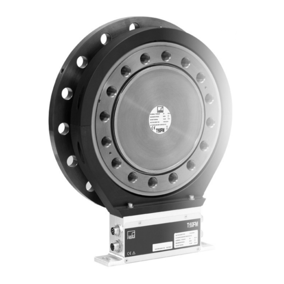
Sign In
Upload
Manuals
Brands
HBM Manuals
Measuring Instruments
T40FM
HBM T40FM Manuals
Manuals and User Guides for HBM T40FM. We have
2
HBM T40FM manuals available for free PDF download: Mounting Instructions
HBM T40FM Mounting Instructions (154 pages)
Brand:
HBM
| Category:
Measuring Instruments
| Size: 1.47 MB
Table of Contents
English
4
Table of Contents
4
Safety Information
6
Markings Used
12
The Marking Used in this Document
12
Symbols on the Transducer
13
Applications
14
Structure and Mode of Operation
15
Important Precautions During Installation
17
Mechanical Installation
17
Conditions on Site
18
Installation Orientation
18
Installation Options
19
Installation Without Dismantling the Antenna Ring
20
Installation with Subsequent Antenna Ring Mounting
21
Preparing for the Rotor Mounting
22
Mounting the Rotor
25
Installing the Stator
28
Mounting the Rotational Speed Flange
32
Electrical Connection
35
General Information
35
EMC Protection
35
Pin Assignment
36
Supply Voltage
43
Shunt Signal
45
Functionality Testing
46
Rotor Status, LED a (Upper LED)
46
Stator Status, LED B (Lower LED)
47
Loading Capacity
48
Maintenance
49
Waste Disposal and Environmental Protection
50
Dimensions
51
T40FM 15 Knm - 25 Knm
51
T40FM Without Speed Measurement, Option 6, Code 0
51
T40FM 30 Knm - 50 Knm
53
T40FM 60 Knm - 80 Knm
55
(Code a Optional)
57
T40FM 15 Knm - 25 Knm
57
T40FM with Speed Measurement, Option 6, Code
57
T40FM 30 Knm - 50 Knm
59
T40FM 60 Knm - 80 Knm
61
Order Numbers, Accessories
63
Specifications
65
Supplementary Technical Information
75
Deutsch
78
Sicherheitshinweise
80
Verwendete Kennzeichnungen
87
Auf dem Aufnehmer Angebrachte Symbole
88
Anwendung
89
Aufbau und Wirkungsweise
90
Mechanischer Einbau
92
Wichtige Vorkehrungen Beim Einbau
92
Bedingungen am Einbauort
93
Einbaulage
93
Einbaumöglichkeiten
94
Einbau mit nicht Demontiertem Antennenring
95
Einbau mit Nachträglicher Montage des Antennenrings
96
Rotormontage Vorbereiten
97
Montage des Rotors
100
Montage des Stators
103
Montage des Drehzahlflansches (nur Drehzahlmesssystem)
109
Elektrischer Anschluss
111
Allgemeine Hinweise
111
EMV-Schutz
111
Steckerbelegung
112
Versorgungsspannung
119
Shuntsignal
121
Funktionsprüfung
122
Rotorstatus, LED a (Obere LED)
122
Statorstatus, LED B (Untere LED)
124
Belastbarkeit
125
Wartung
126
Entsorgung und Umweltschutz
127
Abmessungen
128
T40FM 15 Knm - 25 Knm
128
T40FM ohne Drehzahlmessung, Option Option 6, Code 0
128
T40FM 30 Knm - 50 Knm
130
T40FM 60 Knm - 80 Knm
132
T40FM 15 Knm - 25 Knm
134
T40FM 30 Knm - 50 Knm
136
T40FM 60 Knm - 80 Knm
138
Bestellnummern, Zubehör
140
Technische Daten
142
Ergänzende Technische Informationen
153
Advertisement
hbm T40FM Mounting Instructions (104 pages)
Torque Flange
Brand:
hbm
| Category:
Industrial Equipment
| Size: 2.29 MB
Table of Contents
English
3
Table of Contents
3
Safety Instructions
5
1 Markings Used
8
Symbols on the Transducer
8
The Markings Used in this Document
9
2 Application
9
3 Structure and Mode of Operation
10
4 Mechanical Installation
12
Important Precautions During Installation
12
Conditions on Site
13
Installation Orientation
13
Installation Options
13
Installation Without Dismantling the Antenna Ring
14
Installation with Subsequent Stator Mounting
15
Preparing for the Rotor Mounting
16
Mounting the Rotor
18
Installing the Stator
20
Mounting the Speed Flange (Speed Measuring System Only)
24
5 Electrical Connection
26
General Information
26
EMC Protection
26
Connector Pin Assignment
27
Supply Voltage
30
6 Shunt Signal
31
7 Functional Testing
32
Rotor Status, LED a (Upper LED)
32
Stator Status, LED B (Lower LED)
33
8 Loading Capacity
34
9 Maintenance
35
10 Waste Disposal and Environmental Protection
35
11 Dimensions
36
T40FM Without Speed Measurement
36
T40FM 15 Knm - 25 Knm
36
T40FM 30 Knm - 50 Knm
37
T40FM 60 Knm - 80 Knm
38
T40FM with Speed Measurement
39
T40FM 30 Knm - 50 Knm
41
T40FM 60 Knm - 80 Knm
43
12 Order Numbers, Accessories
45
13 Specifications
46
14 Supplementary Technical Information
52
Deutsch
53
Sicherheitshinweise
55
1 Verwendete Kennzeichnungen
58
Auf dem Aufnehmer Angebrachte Symbole
58
In dieser Anleitung Verwendete Kennzeichnungen
59
2 Anwendung
59
3 Aufbau und Wirkungsweise
60
4 Mechanischer Einbau
62
Wichtige Vorkehrungen Beim Einbau
62
Bedingungen am Einbauort
63
Einbaulage
63
Einbaumöglichkeiten
63
Einbau mit nicht Demontiertem Antennenring
64
Einbau mit Nachträglicher Montage des Stators
65
Rotormontage Vorbereiten
66
Montage des Rotors
68
Montage des Stators
71
Montage des Drehzahlflansches (nur Drehzahlmesssystem)
74
5 Elektrischer Anschluss
76
Allgemeine Hinweise
76
EMV-Schutz
76
Steckerbelegung
77
Versorgungsspannung
80
6 Shuntsignal
81
7 Funktionsprüfung
82
Rotorstatus, LED a (Obere LED)
82
Statorstatus, LED B (Untere LED)
83
8 Belastbarkeit
84
9 Wartung
85
10 Entsorgung und Umweltschutz
85
11 Abmessungen
86
T40FM ohne Drehzahlmessung
86
T40FM 15 Knm - 25 Knm
86
T40FM 30 Knm - 50 Knm
87
T40FM 60 Knm - 80 Knm
88
Advertisement
Related Products
HBM T40B
HBM T40S7
HBM T40S8
HBM T40S9
HBM T10F
HBM T10F KF1
HBM T10F SF1
HBM T10F SU2
HBM T10S2
HBM T10S3
HBM Categories
Transducer
Measuring Instruments
Accessories
Amplifier
Industrial Equipment
More HBM Manuals
Login
Sign In
OR
Sign in with Facebook
Sign in with Google
Upload manual
Upload from disk
Upload from URL