Sign In
Upload
Manuals
Brands
GREE Manuals
Air Conditioner
SXVD300LCJ/A-K
GREE SXVD300LCJ/A-K Manuals
Manuals and User Guides for GREE SXVD300LCJ/A-K. We have
3
GREE SXVD300LCJ/A-K manuals available for free PDF download: Service Manual
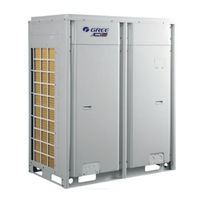
Gree SXVD300LCJ/A-K Service Manual (392 pages)
DC INVERTER MULTI VRF UNITS T1/R410A/50-60Hz
Brand:
Gree
| Category:
Inverter
| Size: 26.22 MB
Table of Contents
Table of Contents
2
Safety Precautions
6
Product List
7
Outdoor Unit
7
Hot Water Generator
7
Chapter 1: Product Introduction
7
Basic Parameter of Unit
8
Water Tank
8
Performance Parameter of Outdoor Unit
8
Performance Parameter of Hot Water Generator
9
Performance Parameter of Water Tank
10
Product Functions
11
Outline of Features
11
Description of Features
11
Basic Operational Principle
12
Flow Diagram of System
12
Instruction of Flow
12
Naming Rules of Outdoor Unit
13
Naming Rules of Indoor Unit
13
Naming Rules of Hot Water Generator
14
Naming Rules of Water Tank
14
Product Model Selection and Collocation
15
Usage Mode 1: Air Conditioner + Hot Water
15
Installation Methods
15
Usage Mode 2: Air Conditioner + Hot Water + Floor Heating
16
Usage Mode 3: Air Conditioner + Floor Heating
17
Revision of Product Capacity
20
Requirement for Connecting Quantity
20
Notices for Model Selection
20
Product Operating Range
20
Capacity Code
20
Capacity Revision Method for Indoor and Outdoor Units
20
Revision of Ambient Temperature and Collocation Rate Capacity
21
Revision of Cooling Capacity
21
Revision of Heating Capacity
28
Revision Coefficient of Heating Water Capacity
35
Revision of Floor Heating Capacity
37
Revision of Length and Fall Difference of Connecting Pipe
39
Heating Frosting Revision Factor
40
Model Selection and Installation
40
Notices for Model Selection
40
Overall Model Selection Steps
42
Usage
42
Air Conditioner+Heating Water+Floor Heating
42
Air Conditioner+Heating Water/Floor
42
Basic Conditions
43
Define Using Demand of User
43
Define Collication Method of Unit
43
Model Selection Example 1: Air Conditioner + Heating Water + Floor Heating, Air Conditioner + Floor Heating
43
Initial Selection of Outdoor Unit
44
Capacity Revision of Outdoor Unit
44
Model Selection of Generator
45
Checkup of Actual Output Capacity of each Indoor Unit
45
Calculation of Floor Heating Load
45
Model Selection of Water Tank
46
Initial Selection of Generator
46
Checkup of Quantity and Capacity of Generator
46
Calculation of Water Consumption
47
Calculation for Water Storage Capacity of Water Tank
47
Design of Floor Heating Engineering
48
Define Model of Water Tank
48
Final Conclusion for Model Selection of Whole Unit
49
Model Selection of Air Conditioner
50
Model Selection Example 2: Air Conditioner + Heating Water
50
Unit Control
51
General Control Method
51
Schematic Diagram of Unit Control
51
Chapter 2: Control
51
Capacity DIP Switch
52
Fan Emergency Operation DIP Switch
52
Explanation on Schematic Diagram
53
Master Unit Setting DIP Switch
53
Master Control System
53
Input and Output Control Quantity
53
Drive Control System
54
Hydro Box Control System
55
Operation Flowchart of Indoor Air Conditioner
56
Cooling Operation
57
Drying Operation
58
Heating Operation
59
Water Heating Operation
60
Cooling and Water Heating Operation
61
Heating and Water Heating Operation
62
Operation Flow of Outdoor Unit
63
Air Supply Operation
63
Remote Controller
69
Indoor Unit Wired Controller
70
Display
70
LCD of Wired Controller
70
LCD Display Instructions
70
Graphics of Buttons
72
Function Instructions of Buttons
72
Installation and Debugging of Wired Controller
72
Dimension of Wired Controller
72
Installation of Wired Controller
73
Selection of Communication Wire
73
Parts of Wired Controller
73
Length of Communication Wire
73
Installation Requirements
74
Wiring Requirements
74
One/Two Wired Controller Control One Indoor Unit
74
Wiring Instructions
75
One/Two Wired Controller Controls Multiple Indoor Units
75
Installation
76
Debugging
77
Set Master Indoor Unit
77
User Parameter Query
77
Disassembly
77
User Parameter Settings
79
List of User Parameter Settings
80
Engineering Parameter Query
82
List of Engineering Parameter Query
82
Engineering Parameter Settings
87
List of Engineering Parameter Settings
88
Hydro Box Wired Controller
92
Display
92
Buttons
94
Installation and Debugging of Wired Controller
95
Parameter Query
99
Parameter Settings
101
Operation Instructions
102
Switch between Water Heating Interface and Floor Heating Interface
102
On/Off of Water Heating
103
Mode Setting of Water Heating
103
Water Temperature Setting of Water Heating
103
Switch of Water Heating Functions
104
Setting of Sunflower Function
104
Setting of Water Heating Water Temperature Auto Setting
105
Setting of High-Temperature Sterilizing
105
Setting of Rapid Water Heating
107
Setting of Water Heating Timer On/Off
107
Setting of Preset Water Heating
110
On/Off of Floor Heating
113
Water Temperature Setting of Floor Heating
113
Switch of Floor Heating Functions
113
Setting of Floor Heating Water Temperature Auto Setting
114
Setting of Rapid Floor Heating
114
Setting of Floor Heating Absence Function
114
Setting of Floor Heating Timer On/Off
114
Setting of Clock
116
Malfunction Display
117
Setting of Cleaning
117
Remote Shield
117
Child Lock
117
Table of Malfunction Codes for Outdoor Unit
118
Table of Malfunction Codes for Hydro Box
122
Table of Commissioning Codes
122
Table of Status Codes
123
Engineering Installation Flowchart
124
Chapter 3 Installation
124
Common Tools and Devices
125
Preparation before Installation
127
Notices for Installation Engineering
127
Safety Requirements for Installation Engineering
127
Importance of Installation Engineering
127
Cooperation between Different Professions
128
Onsite Review of Design Drawing
129
Requirements for Cooperation with Civil Engineering
129
Requirements for Cooperation with Decoration Engineering
129
Requirements for Cooperation with Electric
129
Selection of Installation Materials
130
Requirements for Selecting Installation Materials
131
Copper Pipe
131
Condensate Water Pipe
131
Insulation Material
131
Water System Pipe
132
Floor Heating Pipe
132
Communication Cable
132
Communication Cable Selection for ODU and Idus
132
Three Operation Modes
133
Power Cable
133
Operation Mode 1: Air Conditioning + Water Heating
133
Operation Mode 2: Air Conditioning + Water Heating + Floor Heating
134
Operation Mode 3: Air Conditioning + Floor Heating
135
ODU Dimensions and Installation Hole Size
138
Selection of Outdoor Unit Installation Place
138
Installation Space Requirement for ODU
138
Monsoons Must be Considered During ODU Installation
140
Snow Must be Considered During ODU Installation
140
Installation Space Requirement for Equipment Floor
140
Preparation before Installing Static Pressure Ventilating Duct
140
Installation of Pressure Ventilating Duct
141
Installation Foundation of ODU
143
Installation of IDU
144
Vibration Reduction for ODU
144
Outline Dimension and Installation Hole Dimension of Hydro Box
145
Installation Position of Hydro Box
145
Requirements for Installation Space of Hydro Box (Unit: MM)
145
Installation Procedures of Hydro Box
147
Internal Structure and Pipeline Instruction of Hydro Box
148
Installation of Water Tank
149
Outline Dimension and Installation Dimension of Water Tank
149
Installation Position of Water Tank
150
Installation Notice for Water Tank
150
Design, Installation and Insulation of Refrigerant Pipeline
151
Notices for Pipeline Design
151
Schematic Diagram of Refrigerant Piping
152
Piping Instruction
152
Schematic Diagram for Refrigerant Piping of Top Discharge Outdoor Unit
153
Allowable Length and Height Different of Refrigerant Piping of IDU and ODU
154
Size of Refrigerant Piping
155
Installation and Insulation of Refrigerant Pipe
158
Pipe Installation for Cooling System
158
Processing to Refrigerant Pipes
158
Cut-Off and Burring
158
Installation of Refrigerant Pipes
159
Operation Sequence
159
Construction of Support, Hanger, and Bracket
159
Shaping and Fixing of Pipes
159
Pipe Connection
160
Welding Protection
160
Requirements on Manifold Installation
161
Pipe Cleaning by Nitrogen
162
Air-Tightness Test
164
Vacuumization and Desiccation for the System
164
Importance of the Air-Tightness Test
164
Procedure for Performing the Air-Tightness Test
164
Insulation for the Refrigerant System Pipe
165
Insulation Materials
165
Thickness of the Insulation Layer
165
Procedure of Insulation
165
Pipe Installation and Insulation for the Condensate Water System and Insulation for the Ducts
166
Installation of Drain Pipes for Different Types of Idus
168
Drain Pipe Installation for Hidden Duct Type IDU
168
Drain Test
169
Full Water Test
169
Drain Pipe Installation for Cassette Type IDU
169
Installation and Insulation of Hot Water System Pipeline
170
Insulation for Air Ducts
170
Connection of Hot Water System Pipeline
170
Insulation for the Condensate Water Pipe
170
Connection Schematic Diagram for Hydro Box and Water Tank
171
Connection Schematic Diagram for Hydro Box and Floor Heating
172
Schematic of Solar Water Heater Connected with System for Heating
172
Connection Schematic of Hydro Box with Water Tank and Floor Heating
172
Connection Requirements of Hydro Box and Water Tank
174
Installation Requirements of Water System
174
Capacity Setting of Water Tank
174
Installation of Floor Heating Performer (Floor Heating Water Separation Valve)
177
Electric Installation
180
Precautions
180
Installation of Power
182
Procedure for Installing the Power Cable
182
Power Cable Diameter and Circuit Breaker Selection
182
Odu
182
Hydro Box
183
Idu
183
External Wiring Diagram of Unit
185
ODU with Hydro Box and IDU
185
Hydro Box and Water Tank
185
Wiring Diagram of ODU
187
Wiring Diagram of Hydro Box
187
Installation of the Communication System
188
Connection of Communication Cable
188
Communication Way
188
Selection of the Material of Communication Cable
188
Communication Cable Selection for Idus/Hydro Box and Wired Controller
189
Communication Cable Selection for ODU and Idus/Hydro Box
189
Setting of Communication Address
190
Connection of Communication Cables
190
Connection Way and Procedures of Communication Cable
191
Connection of Communication Cable between ODU and Idus/Hydro Box
191
Communication Connection between the IDU and Wired Controller
192
One/Two Wired Controller Controlling One IDU
192
One/Two Wired Controller Controlling Multiple Idus
193
Communication Connection between the Hydro Box and Wired Controller
194
Connection between the Duct Type IDU and Receiver Board
196
Refrigerant Charging
197
Precautions on Refrigerant Leakage
197
Calculation of Additional Refrigerant Charge Amount
198
Example of Calculation
198
Commissioning Flowchart
200
Safety Notices
200
Preparation before Commissioning
200
Chapter 4 Commissioning Operation
200
Preparation of Commissioning Tools
200
Preparation of Commissioning Papers
201
Inspection before Commissioning
203
Commissioning Operation of Hydro Box
208
Confirm Main Board DIP Switch
208
Capacity DIP Switch of Hydro Box
208
Function DIP Switch of Hydro Box
208
Commissiong Operation
209
Preparation for Commissioning
209
Water System Commissioning
209
Leak Detection
209
Evacuation of Water Tank and User Side Pipeline
210
Re-Evacuation
210
Commissioning Operation of the Entire Unit
211
Settings of Floor Heating Performer and Indoor Unit
211
Preparation for Test Operation
211
Test Operation
211
Commissioning Operation Mode
216
DIP Swith Instructions of GMV5 Unic
225
Function DIP Switch Settings
225
GMV5 Unic Outdoor Unit (GMV-S224W/A-X,GMV-S280W/A-X)
225
System Function Button Operations
230
Introduction to Function Buttons
230
Introduction to Functions
231
List of Functions
231
Description of Functions
232
Function Setting Operations
234
Function Inquiry Operation
240
Resuming Factory Settings
246
Functional Dial Switch of Hydro Box NRQD16G/A-S
247
Functional Application of Hydro Box
247
Hydro Box (NRQD16G/A-S)
247
Engineering Application Functions Operated Via XK56 Wired Controller
248
User Parameter Inquiry List
249
Engineering Parameter Inquiry
252
Engineering Parameter Setting List
258
Failure Display
262
Table of Error Codes
263
Chapter 5 Maintenance
263
Setting of Outdoor Unit Noise Reduction
267
Setting Instruction
267
Effect of Quiret Mode
268
Description of Question
269
Analysis
269
Troubleshooting
269
Instruction for "Leaving out Charging Water" between Generator and Water Tank
269
Analysis in Forms
271
Control
271
Troubleshooting
271
System Faults
276
System Exhaust Temperature Exception
276
Pressure
282
Poor Cooling/Heating Performance
291
Flowchart Analysis
293
High Exhaust Temperature Protection
293
Low Exhaust Temperature Protection
295
System High Pressure Protection
295
System Low Pressure Protection
296
System Refrigerant Lacking Protection
297
System High Pressure Ratio Protection
298
System Low Pressure Ratio Protection
299
Indoor Unit Anti-Freezing Protection
300
Indoor Unit Water Overflow Protection
300
Pressure Sensor Fault
301
Analysis of Drive Control System Faults
302
Inverter Compressor Drive Board IPM Module Over-Temperature Fault
306
Inverter Fan Overcurrent Protection
311
IPM Module Protection Fault
311
Inverter Fan Drive Board IPM Module Over-Temperature Fault
312
Power Distribution Method
315
Introduction on Key Electric Parts
315
Circuit Diagram of Outdoor Unit
316
Circuit Diagram of Hydro Box
316
Assembly and Disassembly of Parts
317
Introduction on Key Parts
317
Assembly and Disassembly of Key Parts
320
Assembly and Disassembly of Outdoor Unit
320
Assembly and Disassembly of Four-Way Valve
322
Assembly and Disassembly of Electric Expansion Valve
323
Assembly and Disassembly of Oil Separator
325
Assembly and Disassembly of Gas Liquid Separator
327
Assembly and Disassembly of Plate Type Heat Exchanger
329
Assembly and Disassembly of Hydro Box
331
Common Maintenance
333
Notice at the Beginning of Use Season
333
Maintenance at the End of Use Season
333
System Vacuum Pumping
333
Outdoor Unit Heat Exchanger
333
Drain Pipe
333
Parts Replacement
333
System Leak Detection
333
Supplement and Charge of Regrigerant
334
Exploded Views and List of Spare Parts
335
List of Parts
335
Outdoor Unit
335
Hydro Box
338
Exploded View
339
Outdoor Unit Heat Exchanger
341
Notices at the Beginning of Use Season
341
Notices at the End of Use Season
341
Chapter 6 Care
341
Drain Pipe
341
Parts Replacement
341
Function Introduction
342
Connection of Computer and Units
342
Chapter 7 Monitoring Software
342
Hardware Introduction
343
Gree USB Data Converter
343
Functions Introduction
343
List of Parts
343
Appearance
344
Communication Board
345
Communication Wire
345
Operation Instruction
345
Installation Notices
345
Software Introduction
346
Board Connection Wire
346
Computer Configuration
346
Installation Requirements
346
CD Playing
347
Installation Flowchart
348
Installation Procedure
348
Install.net Framework 4.0
348
Install Access Driver
352
Install Gree Debugger
355
Install USB Converter Driver
358
Install Gree USB Data Converter
360
Use of Software
365
Introduction of Functions
365
Operation Methods
365
One-Button Commissioning
365
Project Debugging
371
Control Units
375
Other Functions
377
Conversion of Pressure Value
378
Database Saving of Multiple Systems
379
Change Database Saving Path and Rebuild Database
380
Use of USB Converter
381
Usage of Converter
381
Usage of Converter Configuring Software
386
Debugging of Software
389
Flowchart of Debugging
389
Installation Faults
390
Advertisement
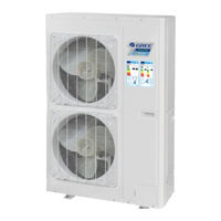
GREE SXVD300LCJ/A-K Service Manual (130 pages)
Air-to-water Heat Pump Split Versati series
Brand:
GREE
| Category:
Air Conditioner
| Size: 9.76 MB
Table of Contents
Table of Contents
2
Product
6
Product Data
6
Lineup
6
Main Unit
6
Water Tank
7
Nomenclature
7
Main Unit
7
Product Features
8
General
8
Features
8
Operating Principle
9
Schematic Diagram
9
Technical Data
10
Parameter List
10
Nominal Working Conditions
14
Operation Range
14
Electric Data
14
Capacity Correction
15
Outline Dimensions
16
Outline Dimensions of Outdoor Unit
16
Outline Dimensions of Indoor Unit
18
Explosive Views and Part Lists
19
Supply Scope
29
Design and Selection
31
Installation Example
31
Model Selection
33
Speculations of Power Supply
33
Operation Conditions
33
Flowchart of Model Selection
34
Design Principle
34
Selection of the Underfloor Coils
34
Calculation of Unit Load for Floor Heating
34
Selection of Tube Spacing of the Underfloor Coils
35
Selection of Loop Quantity of Coils for each Room
35
Type of Underfloor Coils
35
Selection of Loop Quantity for each Room
36
Quantity and Location of the Water Traps and Collectors
36
Design Requirements on Loop Quantity for Circulation Water
36
Requirements on Installation of the Water Trap (Collector)
38
Section of FCU
38
FCU Type Selection
38
Matching of Capacity
38
Selection of the Water Tank
39
Specifications of the Water Tank
39
Volume Selection of the Water Tank
39
Selection Based on Water Consumption Per Capita
39
Selection Based on Sanitary Utensils
40
Selection of the Water Tank
40
Examples for Model Selection
40
General Introduction to the Example Project
40
Heat Load Calculation
40
Load Calculation of a Single Floor
40
Arrangement Design of the Underfloor System for a Single Floor
41
Arrangement Design of the Underfloor System for the Bath Room
41
Arrangement Design of the Underfloor System for the Master and Bath Rooms
41
Check
41
Model Selection
42
Unit Control
43
Integral Control Concept
43
Control Principle Diagram
43
Control Flowchart
46
Main Control Logics
46
Cooling
46
Control to the Compressor
46
Freeze Protection
47
Heating
47
Control to the Compressor
47
Over-Temperature Protection
47
Control to the Auxiliary Electric Heater
47
Water Heating
47
Water Heating by the Main Unit
47
Water Heating by the Solar System
48
Shutdown
48
Control to the Compressor
48
Control to the Fan
48
Control to the 4-Way Valve
49
Control to the Water Pump
49
Control the Electrostatic Expansion Valve
49
Protection Control
49
Controller
50
External View
50
Keys & Indicating Leds
50
Standby Page and Homepage
51
Operation Instructions
52
On/Off
52
Function Setting
53
Parameter Setting (Parameter Set)
73
View
76
General Setting
81
Key Lock
82
Unit Installation
84
Installation Guides
84
Installation Positions of the Outdoor Unit
85
Installation Positions of the Indoor Unit
85
Matters Need Attention
85
Filed Supplied Pipes and Valves
85
Service Tools
87
Instalaltion Instructions
88
Installation Examples
88
Pre-Installation
89
Selection of Installation Location
89
Outline Dimension of Outdoor Unit
90
Installation Clearance Data
92
Outline Dimension of Indoor Unit
92
Installation Clearance Data
93
Installation of Water Tank
93
Electric Wiring
96
Wiring of the Terminal Board
99
Wiring of the 2-Way Valve
101
Wiring of The3-Way Valve
102
Wiring of Other Auxiliary Heat Sources
103
Wiring of the Gate-Controller
103
Wiring of the Remote Air Temperature Sensor
104
Wiring of the Thermostat
105
Wiring of the Control
107
Commissioning and Trial Run
109
Check before Startup
109
Test Run
110
Test Operation & Troubleshooting & Maintenance
112
Trial Run
112
Check for Wiring
112
Check for the Water System
112
Check for the Communication System
112
Trial Run
113
Error Code List
113
Flow Chart of Troubleshooting
115
Comp High-Pressure Protection E1
115
Comp Low- Pressure Protection E3
116
Comp Discharge Temp Protection E4
117
Overload Protection of Compressor or Driver Error
118
DC Fan Error EF
119
Temperature Sensor Error
119
Communication Malfunction E6
120
Capacity Switch Error (Code:"C5")
121
Diagnosis of Driving
121
Diagnosis Flowchart of Driving of Single-Phase Unit and Three-Phase Unit
121
Daily Maintenance and Repair
126
Daily Maintenance
126
Troubleshooting
127
Repair
127
Key Components
127
Charging and Discharging of Refrigerant
129
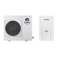
Gree SXVD300LCJ/A-K Service Manual (170 pages)
Air-to-Water Heat Pump
Brand:
Gree
| Category:
Heat Pump
| Size: 8 MB
Table of Contents
Table of Contents
2
Product
3
Models List
4
Main Unit
4
Water Tank
5
Nomenclature
5
Main Unit
5
Water Tank
6
Function
6
Cooling
6
Heating
6
Water Heating
6
Cooling +Water Heating
6
Heating+ Water Heating
7
Emergency Mode
7
Quick Water Heating
7
Holiday Mode
7
Forced Operation Mode
7
Silent Mode
7
Disinfection Mode
7
Weather-Dependent Heating Mode
7
Product Data
8
Product Data at Rated Condition
8
Operation Range
12
Electrical Data
13
Piping Diagram
14
Units Control
16
Operation Flowchart
16
Main Logic
16
Defrosting Mode
16
Water-Side Auto Anti-Freezing in Winter
17
Control of Heating Tape on Chassis
17
Control of Fan
17
Control of Compressor
17
Control of Electric Expansion Valve
17
Wired Controller
18
Dimension
18
Function
18
Installation
66
Control Wiring Design
68
Installation
69
Installation of Units
70
Installation Positions
70
Matters Need Attention
71
Dimension Data
71
Installation Clearance Data
80
Connection of Pipeline
85
Electric Wiring Work
88
Wiring Principle
88
PCB Outline
89
Electric Wiring Design
93
Units Maintenance
108
Error Code List
108
Flow Chart of Troubleshooting
114
Diagnosis of Driving
118
Diagnosis Flowchart of Driving of Single-Phase Unit
119
Diagnosis Flowchart of Driving of Three-Phase Unit
126
Method of Testing Ipm Module Short Circuit
127
Disassembly and Assembly Procedure of Main Parts
134
Exploded Views and Part List
151
Outdoor Exploded View and Part List
151
Indoor Exploded View and Part List
159
Water Tank Exploded View and Part List
165
Advertisement
Advertisement
Related Products
GREE SXVD300LCJ/A-M
GREE SXVD300LCJ2/A-M
GREE SXVD300LCJ2/A-K
GREE SXVD200LCJ/A-K
GREE SXVD200LCJ/A-M
GREE SXVD200LCJ2/A-K
GREE SXVD200LCJ2/A-M
Gree SAP24HP230V1AH
Gree SEER10 Series
Gree SXVD350LCJ/A-K
GREE Categories
Air Conditioner
Heat Pump
Dehumidifier
Controller
Chiller
More GREE Manuals
Login
Sign In
OR
Sign in with Facebook
Sign in with Google
Upload manual
Upload from disk
Upload from URL