
Related Manuals for Gree GMV-S120WL/A-S


Summary of Contents for Gree GMV-S120WL/A-S
- Page 1 GMV5 HOME DC INVERTER MULTI VRF UNITS SERVICE MANUAL T1/R410A /50-60Hz І (GC201509 -...
-
Page 2: Table Of Contents
CONTENTS CHAPTER 1: PRODUCT INTRODUCTION ................... 1 1. P ........................... 1 RODUCT 1.1 Outdoor unit ..........................1 1.2 Hot water generator ........................1 1.3 Water tank ..........................2 2. B ........................ 2 ASIC ARAMETER OF 2.1 Performance parameter of outdoor unit ..................2 2.2 Performance parameter of hot water generator ................ -
Page 3: Table Of Contents
CHAPTER 3 INSTALLATION ......................118 1. E ..................118 NGINEERING NSTALLATION LOWCHART ......................119 OMMON OOLS AND EVICES ....................121 REPARATION BEFORE NSTALLATION 3.1Notices for Installation Engineering ..................121 3.2 Onsite Review of Design Drawing ..................123 3.3 Selection of Installation Materials ..................124 ...................... -
Page 4: Table Of Contents
ONNECTION OF OMPUTER AND NITS ......................337 ARDWARE NTRODUCTION 3.1 List of parts ..........................337 3.2 Gree USB Data Converter ..................... 337 3.3 Communication Board ......................339 3.4 Communication Wire ......................339 ......................340 OFTWARE NTRODUCTION 4.1 Installation Requirements ...................... 340 4.2 Installation Flowchart ...................... - Page 5 6.1 Flowchart of Debugging ......................383 6.2 Troubleshooting ........................384...
-
Page 6: Safety Precautions
It is used to transfer to a designated part. PREFACE Thank you for choosing Gree GMV5 Home Units. For correct installation, operation and maintenance and for reaching the expected performance, please read this manual carefully. This manual is applicable to GMV5 Home Units. -
Page 7: Chapter 1: Product Introduction
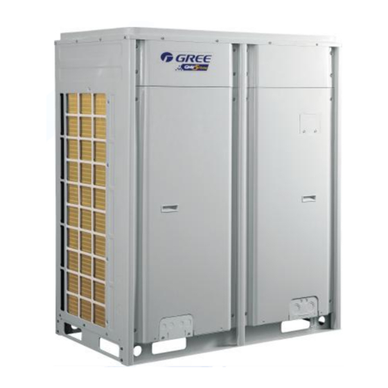
GMV5 Home DC Inverter Multi VRF Units CHAPTER 1: Product introduction 1. Product List 1.1 Outdoor unit Cooling Heating Model Product code capacity capacity Power source Refrigerant Outside view GMV-S120WL/A-S CN853W0110 12.1 14.0 220-240V~ R410a GMV-S140WL/A-S CN853W0120 14.0 16.5 50Hz/60HZ GMV-S160WL/A-S CN853W0130 16.0... -
Page 8: Water Tank
GMV5 Home DC Inverter Multi VRF Units 1.3 Water tank Capacity of water Outside view Model Product code tank SXVD200LCJ/A-K ER20000160 SXVD300LCJ/A-K ER20000180 SXVD350LCJ/A-K ER20000230 SXVD400LCJ/A-K ER20000220 SXVD200LCJ2/A-K ER20000170 SXVD300LCJ2/A-K ER20000190 SXVD350LCJ2/A-K ER20000200 SXVD400LCJ2/A-K ER20000210 Notes: (1) For specific provided capacity of water tank, please refer to the locat climate conditions and suggestion of professional person. -
Page 9: Performance Parameter Of Hot Water Generator
1340×765×16 1340×765×16 dimension (W×D×H) Test voltage of GMV-S120WL/A-S, GMV-S140WL/A-S, GMV-S160WL/A-S is 220V~50HZ; test voltage of GMV-S224W/A-X, GMV-S280W/A-X is 380-415V 3N~50/60HZ. Test working conditions of the above nominal cooling capacity is: indoor dry bulb/wet bulb temperature (27℃ /19℃), outdoor dry bulb/wet bulb temperature (35℃ /24℃);... -
Page 10: Performance Parameter Of Water Tank
GMV5 Home DC Inverter Multi VRF Units Type of heat exchanger Plate heat exchanger Pipe diameter of water Φ25 Connection of inlet/outlet pipe water system Specification of screw thread Φ15.9 Air pipe Connection of Φ9.52 Liquid pipe refrigerant system Φ12.7 High pressure air pipe External dimension (W×D×H) 500×919×328... -
Page 11: P Roduct F Unctions
3. Product Functions 3.1 Outline of Features GMV5 Home is Gree’s latest self-developed air conditioning unit integrated with ―central air conditioner + hot water + floor heating‖. GMV5 Home is an integrated system that a set of air-cooled outdoor unit connecting to several direct evaporative indoor units with the same or different forms or capacities, and at the same time connecting to one or more hot water generators, which can provide one or more different areas with processed air and hot water. -
Page 12: B Asic O Perational P Rinciple
GMV5 Home DC Inverter Multi VRF Units The unit has auto addressing distribution function and non-polar communication function; unit has auto debugging and malfunction detection function; the unit adopts first-created CAN network multi-unit communication technology, which is more reliable and has faster response speed; 4. -
Page 13: Naming Rule
□ - - Description Optional Items Model GMV-Gree multi VRF air conditioner Omitted-T1 work condition; T2-T2 low temperature work condition; T3-T3 high Type of climate temperature work condition Model DC inverter (omitted) Q—heat recovery unit; S—water heater; W—water-cooled chiller; X—fresh air Functional code processing unit;... -
Page 14: Naming Rules Of Hot Water Generator
GMV5 Home DC Inverter Multi VRF Units With water With water pump-S (cassette type unit is acquiescent to be with water pump without pump or not representing S) Named as A, B, C…, and then extended with number 1, 2, 3… Design No. -
Page 15: P Roduct Model Selection And Collocation
6.1 Usage mode 1: air conditioner + hot water Hot water Model of outdoor unit Indoor unit Water tank generator (1) Inner-coil water tank SXVD200LCJ/A-K Side GMV-S120WL/A-S SXVD300LCJ/A-K dischar GMV-S140WL/A-S SXVD350LCJ/A-K GMV-S160WL/A-S SXVD400LCJ/A-K Related indoor unit of (2) Inner-coil water tank... -
Page 16: Usage Mode 2: Air Conditioner + Hot Water + Floor Heating
If it needs to connect to solar energy function, installation methods are as below: 6.2 Usage mode 2: air conditioner + hot water + floor heating Hot water Model of outdoor unit Indoor unit generator Water tank (1) Inner-coil water tank GMV-S120WL/A-S Side SXVD200LCJ/A-K GMV-S140WL/A-S discharge SXVD300LCJ/A-K GMV-S160WL/A-S SXVD350LCJ/A-K SXVD400LCJ/A-K... -
Page 17: Usage Mode 3: Air Conditioner + Floor Heating
If it needs to connect to solar energy function, then connecting methods are as below: 6.3 Usage mode 3: air conditioner + floor heating Usage mode 3: air conditioner + floor heating Model of outdoor unit Indoor unit Hot water generator GMV-S120WL/A-S Side GMV-S140WL/A-S discharge GMV-S160WL/A-S Related indoor unit of GMV5... - Page 18 GMV5 Home DC Inverter Multi VRF Units Installation methos are as below: Notes: Before installation and debugging, please read these prompts carefully! This hot water generator is only used for closed type water system, open type system such as no-coil water tank should not use this hot water generator; it should be installed indoors with ambient temperature of 4℃~35℃.
- Page 19 GMV5 Home DC Inverter Multi VRF Units When connecting hot water generator with water tank, circulation water outlet of hot water generator should connect to circulation water inlet of hot water generator, and circulation water inlet of water tank should connect to circulation water outlet of water tank, for specific installation please refer to instruction manual of hot water generator.
-
Page 20: Requirement For Connecting Quantity
6.4 Requirement for connecting quantity Limit for rated capacity of indoor Limit for quantity of Model unit accounting for rated generator capacity of outdoor unit 80% ~ 100% GMV-S120WL/A-S 80% ~ 100% GMV-S140WL/A-S 80% ~ 100% GMV-S160WL/A-S 80% ~ 100% GMV-S224W/A-X 80% ~ 100%... -
Page 21: Revision Of Ambient Temperature And Collocation Rate Capacity
. 7.3 Revision of ambient temperature and collocation rate capacity 7.3.1 Revision of cooling capacity GMV-S120WL/A-S TC—represents capacity of outdoor unit; PI—represents power of outdoor unit Indoor ambient temperature (℃) 14.0℃ 16.0℃... - Page 22 GMV5 Home DC Inverter Multi VRF Units 6.9 1.26 8.2 1.58 1.96 10.2 2.19 10.9 2.28 11.9 2.32 12.1 2.22 6.9 1.35 8.2 1.70 2.11 10.2 2.36 10.9 2.29 11.6 2.43 11.9 2.38 6.9 1.42 8.2 1.81 2.26 10.2 2.54 10.9 2.55 11.4 2.55 11.7 2.57 6.9 1.49 8.2 1.94 2.41 10.2 2.63 10.9 2.59 11.2 2.64 11.5 2.65 6.9 1.56 8.2 2.06...
- Page 23 GMV5 Home DC Inverter Multi VRF Units 8.8 1.32 10.4 1.62 12.4 1.93 13.1 2.09 13.9 2.22 15.7 2.55 16.6 2.11 8.8 1.36 10.4 1.65 12.4 1.96 13.1 2.13 13.9 2.29 15.7 2.60 16.3 2.14 8.8 1.37 10.4 1.66 12.4 2.00 13.1 2.15 13.9 2.37 15.7 2.66 16.2 2.17 8.8 1.40 10.4 1.71 12.4 2.04 13.1 2.18 13.9 2.45 15.6 2.76 15.9 2.20 8.8 1.43 10.4 1.73 12.4 2.09 13.1 2.23 13.9 2.57 15.5 2.87 15.8 2.25 8.8 1.47 10.4 1.78 12.4 2.15 13.1 2.35 13.9 2.69 15.2 2.93 15.5 2.37...
- Page 24 GMV5 Home DC Inverter Multi VRF Units 7.0 1.07 1.28 2.21 10.5 1.72 11.2 1.98 12.6 2.13 13.9 1.74 7.0 1.09 1.33 1.66 10.5 1.81 11.2 2.02 12.6 2.23 13.9 1.83 7.0 1.12 1.45 1.79 10.5 1.92 11.2 2.13 12.6 2.28 13.9 1.94 7.0 1.21 1.51 1.88 10.5 2.12 11.2 2.24 12.6 2.39 13.9 2.13...
- Page 25 GMV5 Home DC Inverter Multi VRF Units 1.53 11.0 1.85 12.6 2.68 13.6 2.48 14.5 2.84 16.3 3.08 17.3 2.50 1.56 11.0 1.92 12.6 2.40 13.6 2.60 14.5 2.91 16.3 3.20 16.9 2.63 1.62 11.0 2.08 12.6 2.57 13.6 2.77 14.5 3.08 16.3 3.29 16.7 2.80 1.74 11.0 2.17 12.6 2.71 13.6 3.05 14.5 3.23 16.2 3.44 16.5 3.08 1.82 11.0 2.41 12.6 2.94 13.6 3.26 14.5 3.43 16.1 3.61 16.4 3.30 2.01 11.0 2.51 12.6 3.10 13.6 3.49 14.5 3.62 15.8 3.69 16.0 3.52...
- Page 26 GMV5 Home DC Inverter Multi VRF Units 15.1 1.95 18.0 2.36 21.0 2.80 22.4 3.02 23.8 3.28 26.7 3.70 27.2 3.66 15.1 1.99 18.0 2.42 21.0 2.85 22.4 3.08 23.8 3.35 26.3 3.78 26.9 3.83 15.1 2.02 18.0 2.45 21.0 2.94 22.4 3.24 23.8 3.56 25.9 3.97 26.5 4.03 15.1 2.04 18.0 2.48 21.0 3.04 22.4 3.35 23.8 3.68 25.8 4.11 26.3 4.15 15.1 2.09 18.0 2.65 21.0 3.27 22.4 3.60 23.8 3.96 25.4 4.35 25.9 4.39 15.1 2.23 18.0 2.82 21.0 3.48 22.4 3.83 23.8 4.23 25.0 4.51 25.6 4.55...
- Page 27 GMV5 Home DC Inverter Multi VRF Units GMV-S280W/A-X TC—represents capacity of outdoor unit; PI—represents power of outdoor unit Capacity Indoor ambient temperature Outdoor collocation 14.0℃ WB 16.0℃ WB 18.0℃ WB 19.0℃ WB 20.0℃ WB 22.0℃ WB 24.0℃ WB ambient rate of 20.0℃...
- Page 28 15.1 3.36 18.0 4.21 21.0 5.17 22.0 5.91 23.8 6.46 26.8 7.67 27.9 8.00 15.1 3.56 18.0 4.47 21.0 5.50 21.7 6.30 23.8 6.88 26.8 8.17 27.4 8.30 7.3.2 Revision of heating capacity GMV-S120WL/A-S TC—represents capacity of outdoor unit; PI—represents power of outdoor unit Indoor ambient temperature ℃ DB...
- Page 29 GMV5 Home DC Inverter Multi VRF Units -9.5 -10.0 10.5 2.95 10.5 3.17 10.5 3.12 10.5 3.19 10.5 3.21 10.4 3.29 -8.5 -9.1 10.9 3.00 10.9 3.21 10.9 3.16 10.9 3.24 10.9 3.24 10.7 3.34 -7.0 -7.6 11.3 3.07 11.3 3.26 11.3 3.19...
- Page 30 GMV5 Home DC Inverter Multi VRF Units -13.7 -15.0 10.4 3.20 10.4 3.42 10.4 3.70 10.4 3.74 10.4 3.74 10.4 3.74 -11.8 -13.0 11.2 3.28 11.2 3.54 11.1 3.76 11.2 3.80 11.2 3.77 11.1 3.81 -9.8 -11.0 11.6 3.40 11.6 3.60 11.6 3.80...
- Page 31 GMV5 Home DC Inverter Multi VRF Units -3.0 -3.7 14.4 4.09 14.0 4.02 13.4 3.98 12.8 3.88 12.3 3.67 11.6 3.62 -0.7 15.3 4.01 14.0 3.97 13.4 3.87 12.8 3.67 12.3 3.61 11.6 3.59 15.3 3.96 14.0 3.86 13.4 3.66 12.8 3.61 12.3...
- Page 32 GMV5 Home DC Inverter Multi VRF Units -7.0 -7.6 14.9 4.33 14.9 4.46 14.9 4.52 14.9 4.63 14.9 4.67 14.2 4.63 -5.0 -5.6 15.7 4.39 15.7 4.51 15.7 4.61 15.7 4.70 15.7 4.75 14.2 4.57 -3.0 -3.7 16.2 4.45 16.2 4.60 16.2 4.68...
- Page 33 GMV5 Home DC Inverter Multi VRF Units -9.5 -10.0 19.6 6.06 19.5 6.24 19.5 6.42 19.4 6.51 19.4 6.60 19.4 6.78 -8.5 -9.1 20.0 6.12 20.0 6.30 19.9 6.48 19.9 6.57 19.8 6.66 19.8 6.83 -7.0 -7.6 20.7 6.24 20.7 6.42 20.6 6.58...
- Page 34 GMV5 Home DC Inverter Multi VRF Units 22.5 5.45 21.3 5.09 20.0 4.74 19.4 4.56 18.7 4.40 17.5 4.06 22.5 5.14 21.3 4.81 20.0 4.47 19.4 4.32 18.7 4.16 17.5 3.84 22.5 4.85 21.3 4.53 20.0 4.25 19.4 4.08 18.7 3.93 17.5 3.64...
-
Page 35: Revision Coefficient Of Heating Water Capacity
23.6 4.88 22.0 4.52 13.0 11.8 28.4 5.66 26.8 5.30 25.2 4.95 24.4 4.78 23.6 4.61 22.0 4.27 15.0 13.7 28.4 5.35 26.8 5.02 25.2 4.70 24.4 4.53 23.6 4.37 22.0 4.07 7.4 Revision coefficient of heating water capacity GMV-S120WL/A-S、GMV-S140WL/A-S、GMV-S160WL/A-S... - Page 36 GMV5 Home DC Inverter Multi VRF Units Outdoor unit: GMV-S224W/A-X Outdoor unit: GMV-S280W/A-X...
-
Page 37: Revision Of Floor Heating Capacity
GMV5 Home DC Inverter Multi VRF Units 7.5 Revision of floor heating capacity Outdoor unit: GMV-S120WL/A-S Water yielding temperature (℃) Outdoor temperature DB℃ WB℃ Capacity Power Capacity Power Capacity Power Capacity Power -9.8 2.94 2.45 2.47 2.89 -9.5 2.97 2.48 2.50... - Page 38 GMV5 Home DC Inverter Multi VRF Units -8.5 -9.1 11.5 3.60 3.00 3.03 3.38 -5.6 12.6 3.71 10.5 3.10 3.14 3.26 -3.7 12.2 3.68 10.1 3.06 3.13 3.33 -0.7 11.6 3.62 3.02 3.13 3.43 13.9 3.78 11.6 3.15 11.2 3.50 10.7 3.64 15.4...
-
Page 39: Revision Of Length And Fall Difference Of Connecting Pipe
4.61 28.0 5.77 28.0 6.57 28.0 7.51 7.6 Revision of length and fall difference of connecting pipe GMV-S120WL/A-S、GMV-S140WL/A-S、GMV-S160WL/A-S 1) Change rate of cooling capacity 2) Change rate of heating capacity GMV-S224W/A-X、GMV-S280W/A-X Hp(m) 20 Hp(m) 20 30 40 50 70 80... -
Page 40: Heating Frosting Revision Factor
GMV5 Home DC Inverter Multi VRF Units Hm: Height difference (m) between two units when indoor unit is in higher powition of outdoor unit; L: One way equivelent pipe length 7.7 Heating frosting revision factor When outdoor environment satisfies certain conditions (temperature and humidity conditions), unit may appears frosting or defrosting situation, which will weaken heating capacity of whole unit, thus please calculate frosting revision factor for heating load model selection. - Page 41 220V~, normally closed type), and controlling on and off of shunt valve of designated should connect power cord to electric room is proviced by Gree (it should set linkage box of Gree generator, and function). There is no need for users to purchase floor automatically controlled by generator.
-
Page 42: Overall Model Selection Steps
GMV5 Home DC Inverter Multi VRF Units 8.1.2 Usage Item Contents It is suggested that in summer, temperature of hot water can be set around 45℃; in winter, Using hot temperature of hot water can be set to be 50℃ or below 50℃. water It’s better to use hot water in higher temperature of a day in winter (It can set via preset, timer, sunflower and related functions, preset and timer functions are circularly effective). -
Page 43: Model Selection Example 1: Air Conditioner + Heating Water + Floor Heating, Air Conditioner Floor Heating
GMV5 Home DC Inverter Multi VRF Units indoor unit and outdoor unit; procedures for model selection are the same as that of general multi VRF unit. Model selection of water tank——select model of water tank according to water using demand of user; capacity of inner-coil water tank (tie-in generator) is 200/300/350/400L. - Page 44 GMV5 Home DC Inverter Multi VRF Units Load (kW) Specification 25 type 25 type 36 type 36 type 36 type 36 type 36 type 45 type Capacity code 8.3.4.2 Initial selection of outdoor unit (1) Basic principle for model selection of outdoor unit: Know well about using habit of user, before using the unit, total capacity of indoor units operated simultaneously should not be larger than capacity of outdoor unit, otherwise it may cause deficiency in cooling (heating) of indoor units.
- Page 45 GMV5 Home DC Inverter Multi VRF Units (3) Capacity revision coefficient of pipe length and height difference Upon inquiry, for the corresoponding length of pipe is 30m and height difference between indoor and outdoor unit is 10m (outdoor unit is in lower position), the revision coefficient is 0.95. 【For specific revision contents of connecting pipe please see related instruction manual】...
- Page 46 Limit for rated capacity of indoor unit Limit for Model accounting for rated capacity of quantity of outdoor unit generator 80% ~ 100% GMV-S120WL/A-S 80% ~ 100% GMV-S140WL/A-S 80% ~ 100% GMV-S160WL/A-S 80% ~ 100% GMV-S224W/A-X 80% ~ 100% GMV-S280W/A-X Checkup of floor heating capacity of generator should calculate according to floor heating capacity of outdoor unit.
- Page 47 GMV5 Home DC Inverter Multi VRF Units Model selection principle: calculate ―water consumption of user‖ according to ―number of people and per capita water consumption‖ and ―water consumption of bathroom accessories‖ respectively, and take the larger value. And then calculate ―water storage capacity of water tank‖, that is, cubic capacity of water tank.
- Page 48 GMV5 Home DC Inverter Multi VRF Units using the water, generally it takes 60℃; t cooling water entering temperature——cooling water entering temperature is selected according to regions; east China region can take 5℃; t heating temperature of water tank—— in consideration of energy-saving purpose, generally it takes 50℃.
- Page 49 GMV5 Home DC Inverter Multi VRF Units valve) should install electric shunt valve (single phase 220V~, normally closed type), and should connect power cord to electric box of Gree generator, and automatically controlled by generator. Set wired controller of air conditioner to control shunt valve of designated room.
-
Page 50: Model Selection Example 2: Air Conditioner + Heating Water
GMV5 Home DC Inverter Multi VRF Units 8.4 Model selection example 2: air conditioner + heating water 8.4.1 Basic conditions Applicable location: general villa. Temperature conditions: take cooling load as principle of model selection --- outdoor temperature: 35℃DB; indoor wet bulb temperature: 21℃WB. Cooling load: Room Room A... -
Page 51: Chapter 2: Control
GMV5 Home DC Inverter Multi VRF Units Chapter 2: Control 1. Unit Control 1.1 General Control Method 1.1.1Schematic Diagram of Unit Control Inverter drive control system Main board of master outdoor unit Temp Curr eratur High Electronic Relay voltage trans expansion senso output... - Page 52 GMV5 Home DC Inverter Multi VRF Units Capacity DIP Switch (SA1): DIP switch (5 digits) Outdoor capacity code Remark: Only when the outdoor unit capacity DIP switch is correctly set, will the unit be able to run normally. If setting is wrong, outdoor unit will report capacity DIP switch error. Centralized Control Address DIP Switch (CAN network address, SA2) DIP switch (5 digits) CAN2 address...
- Page 53 GMV5 Home DC Inverter Multi VRF Units Error of fan 2 Remark: Only one fan can be set to emergency mode. If two or more fans are set to emergency mode, outdoor unit will report emergency operation setting error. Static Pressure Setting DIP Switch (SA6) Static pressure setting DIP switch SA6 Static pressure(Pa) DIP1...
- Page 54 GMV5 Home DC Inverter Multi VRF Units unit. Controller will adjust the compressor frequency according to the sensed temperature. High pressure sensor is used to sense the discharge pressure of outdoor unit. Controller will judge the corresponding fan speed, compressor frequency, electronic expansion valve opening position according to the sensed high pressure.
- Page 55 GMV5 Home DC Inverter Multi VRF Units Hydro Box Control System Main board of hydro box: It communicates with outdoor unit, long-distance monitor and indoor air conditioners through the CAN bus. Besides, it supplies power to and communicates with wired controllers through HBS bus.
-
Page 56: Operation Flowchart
GMV5 Home DC Inverter Multi VRF Units 1.2 Operation Flowchart 1.2.1 Operation Flowchart of Indoor Air Conditioner Power on Initialization of electric expansion valve LED is on stop LED Off Run/Stop Error code is Whether protection displayed and LED device is started blinks Press Run/Stop Whether the LED... - Page 57 GMV5 Home DC Inverter Multi VRF Units Cooling Operation Cooling Operation There Is Not Guide Louver There Is Guide Louvers Swing Fan Motor: Operation In The Process Of Preventing Restart Operation? (3 Minutes) Temperature Adjustment? Fan Motor:Stop Electronic Expansion Valve: Close Electronic Expansion Valve: Capacity Control (Go To The Previous Page)...
- Page 58 GMV5 Home DC Inverter Multi VRF Units Drying Operation Drying Operation Guide Louver Guide Louvers Swing Fan Motor: low speed In the Process of Preventing Restart Operation? (3 minutes) Temperature Adjustment? Fan Motor: Stop Electronic expansion valve: Close Electronic Expansion Valve: Capacity Control...
-
Page 59: Heating Operation
GMV5 Home DC Inverter Multi VRF Units Heating Operation Heating Operation There Is Not Guide Louver There Is Guide Louvers Swing In The Operation Of Defrosting? In The Process Of Preventing Restart Operation? (3 Minutes) Temperature Adjustment? In The Process Of Fan Motor: Stop Fan Motor: Stop Preventing Cold Air? - Page 60 GMV5 Home DC Inverter Multi VRF Units Water Heating Operation Water heating Power LED: On On defrosting? Adjust Temp Start water pump and Water pump stops add hot water...
- Page 61 GMV5 Home DC Inverter Multi VRF Units Cooling and Water Heating Operation Cooling and water heating Guide louver Guide louver swings On preventing it from running again? (3min) Adjust temp ? On anti-cold air ? Fan: setting speed Fan: stop Fan: stop Electric expansion Start water pump...
- Page 62 GMV5 Home DC Inverter Multi VRF Units Heating and Water Heating Operation Heating and Water heating Guide louver Guide louver swings On defrosting? On preventing it from running again? (3min) Adjust temp On anti-cold Fan: setting Fan: stop Fan: stop Fan: stop speed Electric...
- Page 63 GMV5 Home DC Inverter Multi VRF Units Air Supply Operation Air supply Guide louver Guide louver swings Fan: setting speed Electric expansion valve: controlled by mode of air supply 1.2.2 Operation Flow of Outdoor Unit Power on Commissioni ng is done or not? Heating mode, heating...
- Page 64 GMV5 Home DC Inverter Multi VRF Units Cooling Operation Cooling standby Cooling starts Open and close 4-way valve. Compressor starts up There is Unit stops malfunction because of or not? malfunction. In the Malfunction is operation of eliminated. oil return? Oil return is in operation.
- Page 65 GMV5 Home DC Inverter Multi VRF Units Heating Operation Heating standby Heating starts up? Open and close 4-way valve. Compressor starts up. There is Unit stops malfunction because of or not? malfunction In the Malfunction is In defrosting? operation of eliminated.
- Page 66 GMV5 Home DC Inverter Multi VRF Units Water Heating Operation Water heating standby Water heating starts Open and close 4-way valve Compressor starts up. There is Unit stops malfunction because of or not? malfunction. In the Malfunction is In defrosting? operation of eliminated.
- Page 67 GMV5 Home DC Inverter Multi VRF Units Cooling and Water Heating Operation Cooling and water heating standby Cooling and water heating ? start up? Heat Open and exchanger Condenser Compressor close 4-way used as starts up valve. evaporator/ condenser. Evaporator Open and There is...
- Page 68 GMV5 Home DC Inverter Multi VRF Units Heating and Water Heating Operation Heating and water heating standby Heating and water heating start up? Open and close 4-way valve. Compressor starts up. There is Unit stops malfunction because of or not? malfunction.
-
Page 69: R Emote C Ontroller
GMV5 Home DC Inverter Multi VRF Units 2. Remote Controller Button name Function ON/OFF Turn on or turn off the unit TURBO Set turbo function MODE Set operation mode Set up&down swing status I FEEL Set I FEEL function TEMP Switch temperature displaying type on the unit’s display Set health function and air function LIGHT... -
Page 70: Indoor Unit Wired Controller
GMV5 Home DC Inverter Multi VRF Units Set timer on function Set left&right swing status Set fan speed Set temperature and time 3. Indoor Unit Wired Controller 3.1 Display Fig.1.1 Wired Controller 3.1.1 LCD of Wired Controller Fig.1.2 LCD Display of Wired Controller 3.1.2 LCD Display Instructions Table 1.1 LCD Display Instructions... - Page 71 GMV5 Home DC Inverter Multi VRF Units Name Instructions Auto mode (Under Auto mode, indoor units will automatically select their operating Auto* mode as per the temperature change so as to provide comfort.) Up and down swing Up and down swing function Cooling Cooling mode Left and right swing*...
-
Page 72: Buttons
GMV5 Home DC Inverter Multi VRF Units 3.2 Buttons 3.2.1 Graphics of Buttons Fig.2.1 Graphics of Buttons 3.2.2 Function Instructions of Buttons Table 2.1 Function Instructions of Buttons Name Functions (1) Set up & down swing function Swing/Enter (2) Select and cancel function Timer Timer setting (1) Set operating temperature of indoor unit... - Page 73 GMV5 Home DC Inverter Multi VRF Units Fig.3.2 Parts of Wired Controller Wiring box Panel of wired Soleplate of wired Name Screw M4X25 mounted in the controller controller wall Quantity 1 pc 2 pc 1 pc Prepared by user 3.3.1 Installation of Wired Controller 3.3.1.1 Selection of Communication Wire Fig.3.3 Length of Communication Wire Total length of...
- Page 74 GMV5 Home DC Inverter Multi VRF Units ② Materials of communication wire for wired controller must be selected according to this manual strictly. 3.3.1.2 Installation Requirements (1) Never install the wired controller at wet places. (2) Never install the wired controller under direct sunlight. (3) Never install the wired controller at a place near high temperature objects or water-splashing places.
- Page 75 GMV5 Home DC Inverter Multi VRF Units Fig.3.6 One Wired Controller Controls Multiple Indoor Units Simultaneously Fig.3.7 Two Wired Controllers Control Multiple Indoor Units Simultaneously Wiring instructions: (1) When one wired controller controls multiple indoor units simultaneously, the wired controller can connect to any one indoor unit, but the connected indoor unit must be the same series indoor unit.
- Page 76 GMV5 Home DC Inverter Multi VRF Units controller can't be more than 16 sets and all connected indoor units must be within the same indoor unit network. Number of indoor units of group control must be set for wired controller. Please refer to section 3.2.3. (4) When one (or two) wired controller(s) control(s) multiple indoor units at the same time, the controlled indoor unit's setting should be the same.
- Page 77 GMV5 Home DC Inverter Multi VRF Units 3.3.1.5 Disassembly Fig.3.9 Disassembly of Wired Controller 3.3.2 Debugging 3.3.2.1 Set Master Indoor Unit Under Off status, long press "MODE" button for 5s to set the corresponding indoor unit of wired controller as master indoor unit. When it is successfully set, "MASTER" icon will light up. Note: (1) If master indoor unit already exists in the network, you can also set the other unit to be a master unit.
- Page 78 GMV5 Home DC Inverter Multi VRF Units query, buzzer of the indoor unit operated by the wired controller will ring until user quits "C01" query or switches to the next indoor unit. Indoor unit quantity Timer zone displays the total number of indoor units in the query in the system 1-80 system.
- Page 79 GMV5 Home DC Inverter Multi VRF Units unit in the interface of "C17". Operation method ("C18" function is not available for slave wired controller): Setting: In "C18" status, press "MODE" button to enter the interface of indoor unit project code query. Press "▲" or "▼" button to select an indoor unit.
- Page 80 GMV5 Home DC Inverter Multi VRF Units 3. Press "SWING/ENTER" button to return to the previous step until exiting parameter settings. The user parameter setting list is as below: Table 3.2 List of User Parameter Settings Paramete Default Parameter name Parameter range Remarks r code...
- Page 81 GMV5 Home DC Inverter Multi VRF Units 01: High height of ceiling installation 00: Common Setting of timer timing function 01: Time-point timing Effectiveness of 00: Single timing This setting is valid only when the timer repeated 01: Repeat every function is set to time-point timing.
- Page 82 GMV5 Home DC Inverter Multi VRF Units unit After linkage function is set, fresh air indoor unit will be powered on or off with the Setting of linkage 00: No linked power-on or power-off of common indoor for fresh air indoor control units.
- Page 83 GMV5 Home DC Inverter Multi VRF Units Project 1-255:Proje number ct number; query of 00: No Timer zone displays the project number of master indoor unit/ 00. master indoor master unit indoor unit Operation method: 1. In ―C05‖ status, press ―MODE‖ button to enter the historical error query interface.
- Page 84 GMV5 Home DC Inverter Multi VRF Units temperature to switch the number of indoor unit. sensor of Display mode: indoor unit Temperature zone displays the project number of the current indoor unit. Timer zone displays the temperature value. If the HBS network consists of only one indoor unit, timer zone will directly display the temperature value in "C15"...
- Page 85 GMV5 Home DC Inverter Multi VRF Units query ingress controller): 25~29 In ―n7‖ status, the timer zone is not displayed. Press ―MODE‖ button of outdoor unit to enter parameter query of outdoor unit. The first bit in the temperature zone (display bit of the outdoor unit module ID) blinks. Press "▲"...
- Page 86 GMV5 Home DC Inverter Multi VRF Units (Actual value = Displayed value*10) Sub-cooler EXV (Actual value = Displayed value*10) ℃/℉ Defrosting temperature Liquid-extracting ℃/℉ temperature of sub-cooler Outlet tube temperature of ℃/℉ gas separator ℃/℉ Oil return temperature Inlet tube temperature of ℃/℉...
- Page 87 GMV5 Home DC Inverter Multi VRF Units ―▲‖ to barcode of the display entire upward. indoor unit. indicate s the 0128 former 7 bits of barcode indicate s the latter 6 bits of barcod. indicate s that followin g is the barcode of indoor unit...
- Page 88 GMV5 Home DC Inverter Multi VRF Units Press and hold "FUNCTION" button for 5 seconds and the temperature zone displays "C00". Continue to press "MODE" button for 3 times, and then press and hold "FUNCTION" button for 5 seconds to enter the interface of engineering parameter settings.
- Page 89 GMV5 Home DC Inverter Multi VRF Units of ambient sensor of unit: decrease by 1℃. temperature 0℃; sensor of indoor Temperature unit(for cooling, sensor of wired drying and fan controller: 0℃ mode) Press ― ‖ or ― ‖ to increase or decrease by 1℃.
- Page 90 GMV5 Home DC Inverter Multi VRF Units the upper-level menu. One-key reset When it is set to 01, the wired 00: Invalid for indoor unit controller initiates an indoor unit 01: Valid project number project number reset command. Minimum opening degree After the default minimum opening setting for 00: Automatically...
- Page 91 GMV5 Home DC Inverter Multi VRF Units operating mode allowed to be on mode, energy efficiency test mode, AHRI test mode); If it is set to 01, water pump works as normal. There are 13 levels of static pressure of DC fresh air unit. Each level is corresponding to a speed value.
-
Page 92: Hydro Box Wired Controller
GMV5 Home DC Inverter Multi VRF Units 4. Hydro Box Wired Controller 4.1 Display 4.1.1 LCD of Wired Controller 4.1.2 LCD Display Instructions Name Instructions When wired controller displays water heating function, the corresponding frame Water heating will be lit up. - Page 93 GMV5 Home DC Inverter Multi VRF Units Water heating The icon of hot water is lit up. Icon of on/off will be displayed along with the on/off on/off of water heating. Standard water Standard water heating heating Preset Preset water heating It indicates the percentage of usable hot water.
- Page 94 GMV5 Home DC Inverter Multi VRF Units Timer zone It displays system clock and timer state. Invalid It is displayed when operation is invalid. Remark: Functions may vary if wired controller matches with a different hydro box. 4.2 Buttons 4.2.1 Graphics of Buttons 4.2.2 Function Instructions of Buttons Name Functions...
-
Page 95: Installation And Debugging Of Wired Controller
GMV5 Home DC Inverter Multi VRF Units 4.3 Installation and Debugging of Wired Controller Unit: mm Panel of wired Soleplate of Name Screw M4X25 Wiring box mounted in the wall controller wired controller Quantity 1 pc 2 pc 1 pc Prepared by user 4.3.1 Installation of Wired Controller 4.3.1.1 Selection of Communication Wire... - Page 96 GMV5 Home DC Inverter Multi VRF Units twisted copper cord strong (RVVSP) electromagnetic interference, use shielding wire (RVVSP). Note: ①If air conditioner is installed in a place with strong electromagnetic interference, communication wire of wired controller must be shielding twisted pair. ②Materials of communication wire for wired controller must be selected according to this manual strictly.
- Page 97 GMV5 Home DC Inverter Multi VRF Units Wiring instructions: When one wired controller controls multiple hydro boxes simultaneously, the wired controller can connect to any one hydro box, but all the connected units must be hydro boxes. The total quantity of hydro box controlled by wired controller can't exceed 3 sets, and the connected hydro box must be within the same network.
- Page 98 GMV5 Home DC Inverter Multi VRF Units any one hydro box, but all the connected units should be hydro boxes. The addresses of those two wired controllers should be different. Please refer to section 4.3.2.2 for the setting method. The total quantity of hydro box controlled by wired controller can't be more than 3 sets and all connected hydro boxes must be within the same network.
- Page 99 GMV5 Home DC Inverter Multi VRF Units 4.3.1.5 Disassembly 4.3.2 Debugging 4.3.2.1 Parameter Query Unit’s parameters can be queried under power-on or power-off status. 1. Press and hold ―FUNCTION‖ button for 5 seconds to enter the interface of parameter query. ―C00‖...
- Page 100 GMV5 Home DC Inverter Multi VRF Units current hydro box. Wired controller 01, 02 Timer zone displays the address of current wired controller. address query Hydro box quantity query in the case that Timer zone displays the total number of hydro boxes controlled by one wired the wired controller.
-
Page 101: Parameter Settings
GMV5 Home DC Inverter Multi VRF Units Press ―MODE‖ button in ―C21‖ status to enter the interface of water temperature tank water temperature query. Press ‖▲" or "▼" button to switch query for water the number of hydro box. heating Display mode: Temperature zone displays the project number of the current hydro box. -
Page 102: Operation Instructions
GMV5 Home DC Inverter Multi VRF Units setting value of water temperature keeping function for water tank standby status Water temperature setting of 35~50℃ 40℃ sunflower water temperature keeping function Corrected value of water heating water -2~8℃ 0℃ temperature auto setting Cycling days of If it is set to 0, high-temperature... - Page 103 GMV5 Home DC Inverter Multi VRF Units ―WATER/AC/FLOOR‖ button to switch between water heating interface and floor heating interface. On the interface of floor heating, user can switch to the interface of water heating by pressing ―WATER/AC/FLOOR‖ button. On the interface of water heating, user can switch to the interface of floor heating by pressing ―WATER/AC/FLOOR‖...
- Page 104 GMV5 Home DC Inverter Multi VRF Units temperature by 1℃. Holding ―▲‖ or ―▼‖ button will increase or decrease set temperature by 1℃ every 0.3 seconds. Under Standard Water Heating, Preset Water Heating and Nighttime Water Heating, temperature setting range is 35℃~maximum water temperature for water heating. Default water temperature is 50℃.
- Page 105 GMV5 Home DC Inverter Multi VRF Units button to switch to sunflower function. Then press "ENTER/CANCEL" to cancel sunflower function. 4.4.7 Setting of Water Heating Water Temperature Auto Setting Water heating water temperature auto setting: Water heating water temperature will be set automatically by main board according to outdoor ambient temperature.
- Page 106 GMV5 Home DC Inverter Multi VRF Units Cancellation of high-temperature sterilizing: On the interface of water heating, press ―FUNCTION‖ button to switch to sterilizing. Press ―ENTER/CANCEL‖ button to cancel the setting. Note: ①Preset time for sterilizing defaults to null and timer zone displays ―--: --‖. ②Cycling days for sterilizing can be adjusted by professional operators.
- Page 107 GMV5 Home DC Inverter Multi VRF Units 4.4.9 Setting of Rapid Water Heating Rapid water heating: Under the condition allowed by outdoor unit, start compressor and electric heating to heat up water rapidly. Setting of rapid water heating: Under water heating mode, press ―FUNCTION‖ button to switch to rapid function.
- Page 108 GMV5 Home DC Inverter Multi VRF Units Cancellation of water heating timer on is as below:...
- Page 109 GMV5 Home DC Inverter Multi VRF Units Cancellation of water heating timer off is as below:...
- Page 110 GMV5 Home DC Inverter Multi VRF Units 4.4.11. Setting of Preset Water Heating Setting of preset water heating: Under water heating mode, press ―MODE‖ button to switch to preset mode (Then wired controller will remind user to set the preset time. If unit is already in preset mode, skip this step). Press ―TIMER‖...
- Page 111 GMV5 Home DC Inverter Multi VRF Units...
- Page 112 GMV5 Home DC Inverter Multi VRF Units Cancellation of preset water heating is as below:...
- Page 113 GMV5 Home DC Inverter Multi VRF Units 4.4.12. On/Off of Floor Heating On/Off of floor heating: On the interface of floor heating, press ―ON/OFF‖ button, and floor heating will be on or off. On the interface of water heating: press ―WATER/AC/FLOOR‖ button once to activate the interface of floor heating.
- Page 114 GMV5 Home DC Inverter Multi VRF Units Floor heating is on/off Functions Remarks Floor Heating Water Temperature Auto Setting, Floor heating is on Rapid Floor Heating, Absence Floor heating is off Absence On the interface of floor heating, when floor heating is turned on, pressing ―FUNCTION‖ button once will change floor heating functions circularly as below: When floor heating is turned off, only the absence function will be available.
- Page 115 GMV5 Home DC Inverter Multi VRF Units Cancellation of floor heating timer: Press ―TIMER‖ to enter the setting of timer. Pressing ―TIMER‖ button can switch between timer on and timer off. Press ―ENTER/CANCEL‖ to cancel floor heating timer. Setting of floor heating timer is as below: Cancellation of floor heating timer on is as below:...
- Page 116 GMV5 Home DC Inverter Multi VRF Units Cancellation of floor heating timer off is as below: 4.4.19 Setting of Clock Clock display: Timer zone will display system clock whether unit is turned on or not. When icon blinks, user can set the clock. System clock: Hold ―TIMER‖...
-
Page 117: Malfunction Display
GMV5 Home DC Inverter Multi VRF Units or ―▼‖ for 5 seconds can increase or decrease the time by 10 minutes. Then press ―ENTER/CANCEL‖ button or ―TIMER‖ button to save and exit the setting. Setting of clock is as below: 4.4.20 Setting of Cleaning Start the water pump to drain and clean the waterway for the engineering installation. - Page 118 GMV5 Home DC Inverter Multi VRF Units Note: If malfunction occurs, please turn off the unit and send for professionals to repair. Below is a display when the quantity of group controlled hydro boxes is inconsistent. 4.5.1 Table of Malfunction Codes for Outdoor Unit Content symbol Distinctive symbol...
- Page 119 GMV5 Home DC Inverter Multi VRF Units ambient temperature temperature sub-cooler sub-cooler temperatur sensor 1 sensor 2 outflow exhaust e sensor temperatur temperatur e sensor e sensor Compresso Inverter Compressor Compressor Compressor r drive Compresso compresso drive board drive module drive board board r drive PFC...
- Page 120 GMV5 Home DC Inverter Multi VRF Units temperature temperatur sensor sensor 1 e sensor (outlet tube Compresso Compresso Compressor Compressor Inverter Compressor r drive r drive DC drive IPM drive IPM compressor drive storage temperatur bus high module over-temperatur out-of-step chip e sensor voltage...
- Page 121 GMV5 Home DC Inverter Multi VRF Units reversely. Malfunction Malfunction Compressor Inverter Inverter Inverter compressor drive DC compressor compressor compressor compressor AC drive bus low out-of-phase drive startup current current voltage protection recharging failure protection detection protection circuit circuit Malfunction Variable Fan drive Malfunction...
- Page 122 GMV5 Home DC Inverter Multi VRF Units Communication malfunction Overflow Commissioning between indoor distribution of IP unit and the address receiver board Remote Emergency Restricted Child lock Shielding emergency shutdown operation status status shutdown Eliminate the Outdoor Status long-distance unit shielding Barcode inquiry connection...
- Page 123 GMV5 Home DC Inverter Multi VRF Units frequency fan drive controllers Communication malfunction Malfunction of lack of Indoor unit pipeline malfunction between indoor indoor unit unit and the receiver board Indoor unit project Overflow Outdoor unit pipeline malfunction number conflict distribution of warning IP address...
-
Page 124: Chapter 3 Installation
GMV5 Home DC Inverter Multi VRF Units Chapter 3 Installation 1. Engineering Installation Flowchart Design disclosure Material purchasing Review of onsite installation places Hydro box Indoor unit Connection pipe Outdoor unit installation installation installation installation Water Welding Commun tank Commun Remote Power Remote... -
Page 125: C Ommon T Ools And D Evices
GMV5 Home DC Inverter Multi VRF Units 2.Common Tools and Devices Three-stage distribution box-----Fig. 1 Multifunctional measurement gauge---Fig. 2 The measurement gauge shall be able to withstand higher pressure. The size of connection pipe is different from the previous pipe in order to avoid misuse. ... - Page 126 GMV5 Home DC Inverter Multi VRF Units Note: All tools shall comply with related safety qualification.
-
Page 127: P Reparation Before I Nstallation
GMV5 Home DC Inverter Multi VRF Units 3.Preparation before Installation 3.1Notices for Installation Engineering 3.1.1Safety requirements for installation engineering Warning! All personnel involved in the installation must attend safety education courses and pass corresponding safety examinations before installation. Only qualified personnel can attend the installation. - Page 128 GMV5 Home DC Inverter Multi VRF Units The guide vane of air channel is not Uneven air quantity allocation reduces the overall performance of reasonably manufactured. the air conditioner. The refrigerant pipe or condensate Water can easily condensate and drip to damage the indoor water pipe does not meet the decoration, or even trigger the protection mode of system due to insulation requirement.
-
Page 129: Onsite Review Of Design Drawing
GMV5 Home DC Inverter Multi VRF Units cooperation between different professions such as architecture, structure, electric, water supply and drainage, fire-fighting, and decoration. Pipes must be laid in places away from any automatic spray head for fire-fighting, and must be reasonably arranged to ensure that the pipes fit the electric, luminaries, and decoration. -
Page 130: Selection Of Installation Materials
GMV5 Home DC Inverter Multi VRF Units Content Result The loads of indoor and ODUs must match. The gross rated capacity of the IDU should be set to a value that is 80% to 100% of the rated capacity of the ODU. In actual conditions, if the capacity of concurrently operating IDUs exceeds 100% of the rated capacity of the ODU, the air conditioning system fails to meet the □Passed □Failed... - Page 131 GMV5 Home DC Inverter Multi VRF Units and must meet national and relevant compulsory standards. 3)If environmentally-friendly materials are to be used as required by customers, all such materials must meet national environmental protection requirement and be provided with relevant certificates.
- Page 132 GMV5 Home DC Inverter Multi VRF Units 3.3.2.4 Water system pipe (circulating pipe of hydro box and water inlet and outlet pipe of water tank) 1)Circulating pipe of hydro box: Hot water pipe must be used. The PPR pipe with outer diameter DN25 which is S2.5 series (thickness is 4.2mm) is recommended.
-
Page 133: Three Operation Mode
GMV5 Home DC Inverter Multi VRF Units 3.3.2.7 Power cable Only copper conductors can be used as power cables. The copper conductors must meet relevant national standard and satisfy the carrying capacity of unit. 4 Three Operation Modes 4.1 Operation mode 1: Air conditioning + water heating This solution can satisfy large demand for hot water. -
Page 134: Operation Mode 2: Air Conditioning + Water Heating + Floor Heating
GMV5 Home DC Inverter Multi VRF Units If solar power is to be connected, installation method is as below: 4.2 Operation mode 2: Air conditioning + water heating + floor heating Outdoor model Indoor unit Hydro box Water tank (1) Water tank with internal coil: SXVD200LCJ/A-K SXVD300LCJ/A-K SXVD350LCJ/A-K... -
Page 135: Operation Mode 3: Air Conditioning + Floor Heating
GMV5 Home DC Inverter Multi VRF Units If solar power is to be connected, installation method is as below: 4.3 Operation mode 3: Air conditioning + floor heating Operation mode 3: Air conditioning + floor heating Outdoor model Indoor unit Hydro box GMV-S224W/A-X Top discharge... - Page 136 GMV5 Home DC Inverter Multi VRF Units Notices: Before installation and debugging, please read the following notices carefully! (1) Hydro box is only used for closed-type water system. For open-type water system such as water tank with no coil, please do not use hydro box. It should be installed indoors at ambient temperature of 4~35.
- Page 137 GMV5 Home DC Inverter Multi VRF Units (8) If you need to connect the hydro box with floor heating system or water tank, please install waterline solenoid valve C and solenoid valve D according to units installation diagram. The solenoid valves are used to control the heating of water tank and floor waterline.
-
Page 138: I Nstallation Of Odu
GMV5 Home DC Inverter Multi VRF Units 5.Installation of ODU 5.1 ODU Dimensions and Installation Hole Size Outline dimension of GMV-S224W/A-X, GMV-S280W/A-X (Unit: mm): 5.2 Selection of Outdoor Unit Installation Place ◆The ODU should be installed near bedrooms, studies or meeting rooms; ◆... - Page 139 GMV5 Home DC Inverter Multi VRF Units If there are walls at four sides of unit, please follow the above-mentioned basic space requirement; In principle, if a crown wall (obstacles for keeping out the wind) exists over the machine, a distance of at least 3000mm should be left between the top of the machine and the crown wall.
- Page 140 GMV5 Home DC Inverter Multi VRF Units 5.3.2 Monsoons must be considered during ODU installation 5.3.3 Snow must be considered during ODU installation. In order to prevent covering the air supply and air return by snow, an air supply protective cover and air return protective cover and one foundation shall be applied.
- Page 141 GMV5 Home DC Inverter Multi VRF Units 5.3.4.2 Installation of pressure ventilating duct Two methods are available to connect an ODU to static pressure ventilating duct, they are reserving the unit top cover and removing the unit top cover. When the effective area of air inlet is less than 70% of the total air inlet area of outdoor unit, please introduce exhauster.
- Page 142 GMV5 Home DC Inverter Multi VRF Units ① Pull up the canvas casing reversely and use the steel bar to press the canvas casing tightly onto the counter flange of the steel-plate ventilation duct; Step 5 ② Use a hand-operated electric drill to drill holes and fasten the parts by using tapping screws;...
-
Page 143: Installation Foundation Of Odu
GMV5 Home DC Inverter Multi VRF Units For method 2, since drills are ① Use a steel bar to required on the press tightly the canvas top cover, the casing around the top powder coated cover of the unit. Use a protective layer hand-operated electric Step 4... -
Page 144: Vibration Reduction For Odu
GMV5 Home DC Inverter Multi VRF Units Schematic diagram for making installation foundation 5.5 Vibration Reduction for ODU The ODU must be fixed securely. Apply a thick rubber sheet or corrugated damping rubber pad with thickness of 200 mm or more and width of 100 mm or more between the ODU and the foundation, as shown in the following figures. -
Page 145: I Nstallation Of H Ydro B Ox
GMV5 Home DC Inverter Multi VRF Units 7.Installation of Hydro Box 7.1 Outline dimension and installation hole dimension of hydro 7.2 Installation Position of Hydro Box ◆ The hydro box shall be installed indoors with ambient temperature from 4℃~35℃. Prohibit install the hydro box outdoors. - Page 146 GMV5 Home DC Inverter Multi VRF Units...
-
Page 147: Installation Procedures Of Hydro Box
GMV5 Home DC Inverter Multi VRF Units 7.4 Installation Procedures of Hydro Box Installation steps:... -
Page 148: Internal Structure And Pipeline Instruction Of Hydro Box
GMV5 Home DC Inverter Multi VRF Units 7.5 Internal Structure and Pipeline Instruction of Hydro Box Hydro box mainly consists of water pump, plate heat exchanger, electric heater and electric control, etc. Its internal structure is shown as below:... -
Page 149: I Nstallation Of W Ater T Ank
GMV5 Home DC Inverter Multi VRF Units 8. Installation of Water Tank 8.1 Outline Dimension and Installation Dimension of Water Tank... -
Page 150: Installation Position Of Water Tank
GMV5 Home DC Inverter Multi VRF Units 8.2 Installation Position of Water Tank (1)The water tank shall be installed in the place where the temp is over 0℃. It may be installed outdoors, e.g. balcony, roof or ground, according to the position of water heater. It may also be installed indoor. -
Page 151: D Esign , I Nstallation And I Nsulation Of R Efrigerant P Ipeline
GMV5 Home DC Inverter Multi VRF Units Note: To ensure safety during use of water, the inlet and outlet of water tank must be connected with a specific length of PPR pipe. The length ―L‖ is calculated as below: L≥70×R , in which ―L‖... -
Page 152: Schematic Diagram Of Refrigerant Piping
GMV5 Home DC Inverter Multi VRF Units 4)The refrigerant pipe must be laid away from the manhole of the unit so that sufficient space can be reserved for maintenance. 5) The riser should be installed in the air conditioning tube well, and the horizontal pipe should be placed in the ceiling, if possible. - Page 153 GMV5 Home DC Inverter Multi VRF Units burn the operator. ② Functions of low-pressure check valve: It is mainly used for low pressure detection of the system and refrigerant charging during after-sales maintenance. 2)Piping instruction for hydro box 9.2.2 Schematic diagram for refrigerant piping of top discharge outdoor unit...
-
Page 154: Allowable Length And Height Different Of Refrigerant Piping Of Idu And Odu
GMV5 Home DC Inverter Multi VRF Units 9.3 Allowable Length and Height Different of Refrigerant Piping of IDU and ODU L10: Distance from the first indoor branch pipe to the farthest IDU L11: Distance from the first indoor branch pipe to the nearest IDU The equivalent distance of IDU branch pipe is 0.5m Content Length (m) -
Page 155: Size Of Refrigerant Piping
GMV5 Home DC Inverter Multi VRF Units Notices: ① Separate piping of hydro box and piping of IDU from the position of branch pipe A. ② Under normal condition, the pipe length from IDU branch pipe B to farthest IDU is 40m. When the following conditions are satisfied, the pipe length can reach 90m: a. - Page 156 GMV5 Home DC Inverter Multi VRF Units Selection of branch pipe A (the first branch pipe) Selection of branch A (i.e. first branch) R410A system Outdoor unit Model FQ01B/A Y-type branch GMV-S224W/A-X, GMV-S280W/A-X Selection of branch pipe B (branch pipe between IDUs) Selection of branch B (i.e.
- Page 157 GMV5 Home DC Inverter Multi VRF Units Piping size between branch pipe A and C, branch pipe C and ODU: Dimension of pipe between branch A and C, dimension of pipe between Total number of connected branch C and outdoor unit hydro box: X Gas pipe Liquid pipe...
-
Page 158: Installation And Insulation Of Refrigerant Pipe
GMV5 Home DC Inverter Multi VRF Units 9.5 Installation and Insulation of Refrigerant Pipe 9.5.1 Pipe installation for cooling system 9.5.1.1 Processing to refrigerant pipes 9.5.1.1.1 Cut-off and burring Warning! Use a special-purpose pipe cutter to cut copper pipes instead of using a hacksaw. - Page 159 GMV5 Home DC Inverter Multi VRF Units 1)Put the flaring nuts into the copper pipe; 2)Put the pipe into the root of the pipe expander and the arrange flaring; (1)Before pipe flaring, apply appropriate amount of lubricant on the surface of the opening to ensure smooth pass of flaring nuts and avoid pipe distortion;...
- Page 160 GMV5 Home DC Inverter Multi VRF Units insulation after installation cannot affect the pipe location and elevation. There shall not be flat bending or corrugation on the pipe after piping. Use angle steel support, bracket, round steel hanger, U-type pipe clip, or flat steel to fix pipes outside the insulation layer.
- Page 161 GMV5 Home DC Inverter Multi VRF Units finished. Equip a pressure regulator valve to the nitrogen cylinder. The nitrogen flow is above 4-6 L/min (pressure of 0.02 to 0.05Mpa) and must be regulated based on the pipe caliber. 9.5.1.2.6 Requirements on manifold installation Manifolds are used to divert refrigerant.
- Page 162 Then insert the copper pipe to proper depth. A concave bag for positioning is available to the manifold purchased from Gree. 8)Because the manifold structure is complex, perform with care to ensure tight insulation.
- Page 163 GMV5 Home DC Inverter Multi VRF Units 9.5.1.2.8 During refrigerant pipe installation, ensure a distance above 500 mm between the pipe and the electric box of the unit for maintenance. In a case when the space is not enough, the final piping way must be determined by the technical personnel.
- Page 164 GMV5 Home DC Inverter Multi VRF Units 9.5.1.3 Air-tightness test Precautions: The measuring range of the test pressure gauge for R410A system must be above 4.5MPa. Record the value displayed on the pressure gauge, ambient temperature, and test time. Pressure correction: The pressure changes by 0.01MPa when the temperature changes by 1℃.
- Page 165 GMV5 Home DC Inverter Multi VRF Units 2)Use the perfusing duct to connect the regulator valve and vacuum pump to detection connectors of the gas pipe valve, liquid pipe valve and high-pressure gas pipe valve. 3)Vacuumize for 4 hours and check whether the vacuum degree reaches -0.1MPa or more. If not, leakage may exist.
-
Page 166: P Ipe I Nstallation And I Nsulation For The C Ondensate W Ater S Ystem And I Nsulation For The D Ucts
GMV5 Home DC Inverter Multi VRF Units 2)Wear the insulation sleeve before connecting refrigerant pipes. Users cannot cut the insulation material apart and then wrap up with ties after connecting the pipes by welding. 3)Specifications of the insulation sleeve must match with that of the refrigerant pipes. 4)Reserve a distance of about 200mm near the welding point to protect the insulation sleeve during welding. - Page 167 GMV5 Home DC Inverter Multi VRF Units 4)When connecting three-way pipes, the two-way straight pipes must be laid on the same slope, as shown in the following figures. 5)The condensate water pipe cannot be tied with the refrigerant pipe. 6)A ventilation hole must be provided on the top of the drain pipe to ensure smoother discharge of condensate water.
- Page 168 GMV5 Home DC Inverter Multi VRF Units Install drain trap connectors as shown in the following figure; Install a drain trap connector for each unit; The drain trap connector shall be installed in a way that facilitates trap cleaning. 13)During condensate water pipe installation, ensure a distance above 500 mm between the pipe and the electric box of the unit for maintenance.
- Page 169 GMV5 Home DC Inverter Multi VRF Units 10.1.3.2 Drain pipe installation for cassette type IDU 1)Use pipe clips instead of applying glue to connect the hoses provided upon delivery and plastic pipes on the device. Connect the other end of the joint to the elbow. The height from the suction inlet of the discharge pump is about 200 to 500 mm.
-
Page 170: Insulation For Air Ducts
GMV5 Home DC Inverter Multi VRF Units during full water test; 2)Fill water from the water tray of unit to make water level of water tray higher than the top end of drain pipe. make the pipe full of water; 3)Check each joint of drain pipe to make sure there is no leakage. - Page 171 GMV5 Home DC Inverter Multi VRF Units with the unit. Installation of water pipe of water tank: safety check valve, filter and cutoff valve must be installed in inlet pipe according to the installation diagram of the unit( pay attention to the direction of safety check valve: ―→‖on the valve shall point at water tank).
- Page 172 GMV5 Home DC Inverter Multi VRF Units (2) Connection schematic diagram for hydro box and floor heating (3) Schematic diagram of solar water heater connected with the system for heating (4) Connection schematic diagram of hydro box with water tank and floor heating...
- Page 173 GMV5 Home DC Inverter Multi VRF Units Note: The horizontal distance between hydro box and thermal insulation water tank shall not exceed 5m, and the vertical fall shall not exceed 3m. It is recommended to install the water tank at lower and install the hydro box at upper. If the total waterpower loss between floor heating pipeline and valves exceeds 6m, please add floor heating engineering pump behind the solenoid valve D.
-
Page 174: Connection Requirements Of Hydro Box And Water Tank
GMV5 Home DC Inverter Multi VRF Units the system from freezing. 11.2 Connection Requirements of Hydro box and water Tank Connect hydrobox with water tank by water pipe which can be galvanized pipe or seamless steel pipe, like PVC pipe, PPR pipe, etc. Size of interface Name Screw of joint... - Page 175 GMV5 Home DC Inverter Multi VRF Units...
- Page 176 GMV5 Home DC Inverter Multi VRF Units...
-
Page 177: Installation Of Floor Heating Performer (Floor Heating Water Separation Valve)
GMV5 Home DC Inverter Multi VRF Units 11.5 Installation of Floor Heating Performer (floor heating water separation valve) When connecting floor heating, floor heating performer is recommended to be installed, so that you can control each room separately in order to save energy. This hydro box is with floor heating performer interface (single phase 220V), which can be connected with the floor heating performer. - Page 178 GMV5 Home DC Inverter Multi VRF Units...
- Page 179 GMV5 Home DC Inverter Multi VRF Units...
-
Page 180: E Lectric I Nstallation
GMV5 Home DC Inverter Multi VRF Units 12. Electric Installation 12.1 Precautions Dangerous! ① The electric installation personnel must get related qualification. ②The air conditioning unit is category 1 electrical appliance which requires reliable grounding. ③ The grounding resistance must meet the requirement of local low. ④... - Page 181 GMV5 Home DC Inverter Multi VRF Units Elaborate the method with the installation personnel on site no matter which method is adopted.
-
Page 182: Installation Of Power
GMV5 Home DC Inverter Multi VRF Units 12.2 Installation of Power 12.2.1 Procedure for installing the power cable Step 1: Knock off the knockouts used for threading the external power cable, fit the threading rubber ring to the hole, and thread the power cable through the hole. Connect L1, L2, L3, and N of the power cable, and the grounding cable to L1, L2, L3, and N on the power terminal block and the grounding screw next to the terminal block respectively. - Page 183 GMV5 Home DC Inverter Multi VRF Units Capacity of Min. sectional area Min. sectional area Model Power supply circuit breaker of grounding wire of power cable GMV-S224W/A-X 380V 3N~50Hz GMV-S280W/A-X 380V 3N~50Hz Note: ① The circuit breaker must support magnetic release and thermal release at the same time to protect the system from short circuit and overload.
- Page 184 GMV5 Home DC Inverter Multi VRF Units 20~16A 32~20A 40~32A 50~40A 10.0 10.0 63~50A 16.0 16.0 80~63A 25.0 16.0 100~80A 35.0 16.0 125~100A 50.0 25.0 The breaker capacity and power cable specifications when a circuit breaker is installed on each indoor unit independently. Capacity of circuit Min.
- Page 185 GMV5 Home DC Inverter Multi VRF Units 12.2.3 External wiring diagram of unit 12.2.3.1 ODU with hydro box and IDU Note: Each unit shall be equipped with a circuit breaker for shortcircuit and abnormal overload protection. IDUs and ODU shall be set with the main circuit breaker separately, for connecting or cutting off the main power.
- Page 186 Note: Please set strictly according to actual situation of project. Function DIP S2 of hydro box has 4 digits. ―1‖, ―2‖, ―3‖ and ―4‖ mean ―Gree water tank‖, ―floor heater‖, ―solar power‖, ―self-made water tank‖ respectively. The DIP of each function is applicable: setting to ―number‖...
-
Page 187: Wiring Diagram
GMV5 Home DC Inverter Multi VRF Units water tank For example, S2 as shown in the figure: Note: The black part is the dial rod. 12.3 Wiring diagram 12.3.1 Wiring diagram of ODU Wiring diagram of GMV-S224W/A-X, GMV-S280W/A-X Note: The above wiring diagram is only for reference. Detailed content please refer to the wiring diagram stuck in the electric box of unit. -
Page 188: I Nstallation Of The C Ommunication S Ystem
GMV5 Home DC Inverter Multi VRF Units Note: The above wiring diagram is only for reference. Detailed content please refer to the wiring diagram stuck in the electric box of unit. 12.3.3 Wiring diagram of IDU Please refer to the related manual of IDU. 12.Installation of the Communication System The CAN communication network is adopted for GMV5 Home. - Page 189 GMV5 Home DC Inverter Multi VRF Units between the IDU and ODU. (1) Communication cable selection for IDUs/hydro box and wired controller Total length of communication Number of wire Wire type cables of the IDU pieces x wire Wire standard Remark and wired controller diameter (mm...
-
Page 190: Setting Of Communication Address
GMV5 Home DC Inverter Multi VRF Units 12.1.4 Connection of communication cables (1) Communication lead wire of indoor and outdoor units must be connected in series instead of in star mode. The terminal unit of communication lead wire of indoor and outdoor units must be connected with communication matched resistance (Single unit system is provided as the assembly of outdoor unit). -
Page 191: Connection Way And Procedures Of Communication Cable
GMV5 Home DC Inverter Multi VRF Units 12.3 Connection Way and Procedures of Communication Cable 12.3.1 Connection of communication cable between ODU and IDUs/hydro box Open the electric box cover of ODU, IDU and hydro box. The communication wire goes to the electric box from the hole. - Page 192 GMV5 Home DC Inverter Multi VRF Units 12.3.2 Communication connection between the IDU and wired controller Connection modes for the communication cable between the IDU and wired controller are shown in the following figures: Figure 2 One wired controller controlling one IDU Figure 3 Two wired controllers controlling one IDU...
- Page 193 GMV5 Home DC Inverter Multi VRF Units Figure 4 One wired controller controlling multiple IDUs Figure 5 Two wired controllers controlling multiple IDUs When two wired controllers control several indoor units, wired controllers can be connected with any one of the indoor units, which are required to be of the same series. One and only one of the two wired controllers shall be set as the secondary wired controller.
- Page 194 GMV5 Home DC Inverter Multi VRF Units 01: Primary wired When two wired controllers control one (or more) Wired controller indoor units, the addresses of the controllers must be controller different. Secondary wired controller (address is 02) 02: address does not support unit’s parameter setting except Secondary setting setting of its own address.
- Page 195 GMV5 Home DC Inverter Multi VRF Units Two wired controllers control one hydro box One wired controller controls multiple hydro boxes...
- Page 196 GMV5 Home DC Inverter Multi VRF Units Two wired controllers control multiple hydro boxes Wiring instructions: (1) When one wired controller controls several hydro boxes , the wired controller can connect to any one of the hydro boxes , but the devices connected to wired controller must be either hydro boxes .
-
Page 197: R Efrigerant C Harging
0.3kg /m³ as the maximum allowable refrigerant concentration. ④If the maximum refrigerant concentration exceeds the allowed threshold, the refrigeration system must be redesigned. In this case, separate the refrigeration system into multiple small-capacity refrigeration systems, or adopt other ventilation measures, or contact local Gree sales company. -
Page 198: Calculation Of Additional Refrigerant Charge Amount
① Liquid pipe includes the liquid pipe which ODU connects IDU and the liquid pipe which ODU connects hydro box. ② For GMV-S120WL/A-S, GMV-S140WL/A-S, GMV-S160WL/A-S, if the total liquid pipe length is within 20m, no additional refrigerant charge is needed. - Page 199 GMV5 Home DC Inverter Multi VRF Units (1)Additional refrigerant charge of liquid pipe(kg) = ∑length of liquid pipe × refrigerant charge amount of every meter of liquid pipe Pipe φ9.52 φ9.52 φ9.52 φ9.52 φ9.52 φ9.52 φ9.52 φ9.52 φ9.52 diameter Length Additional charge 0.54...
-
Page 200: Chapter 4 Commissioning Operation
GMV5 Home DC Inverter Multi VRF Units Chapter 4 Commissioning Operation 1.Commissioning Flowchart Preparation before commissioning Checkup of installation effect Checkup of unit Commissioning 2.Safety Notices Warning! All commissioning and maintenance personnel must lean and strictly comply with construction security specifications. Security measures must be taken especially for outdoor operations; Workers of special types of labor, such as refrigerating engineers, electricians, and welders, must have professional certificates. -
Page 201: Preparation Of Commissioning Papers
GMV5 Home DC Inverter Multi VRF Units corresponding refrigerant system …… Wind velocity indicator At present, there are two commissioning methods for unit, one is to operate directly via the button on mainboard of outdoor unit, another is to install special software and conduct commissioning via PC, the PC software can at the same time display parameter of indoor and outdoor units. - Page 202 GMV5 Home DC Inverter Multi VRF Units Outdoor ambient ℃ temperature Supply voltage Frequency Current of compressor Status and parameter of Exhaust ℃ outdoor unit temperature High pressure of ℃ system Low pressure of ℃ system …… Rated capacity Ambient ℃...
-
Page 203: Inspection Before Commissioning
GMV5 Home DC Inverter Multi VRF Units Notch of water Notch pump Water-out ℃ temperature Water-in ℃ temperature …… 3.3 Inspection before Commissioning Caution! Check Table before Commissioning Pass Checked Type Item for checking Reference or not Check if the engineering design drawing is complete. - Page 204 GMV5 Home DC Inverter Multi VRF Units position50m Check if height difference among indoor units are in conformity with design requirement of unit? Check if the length of pipeline between outdoor unit and the 120m farthest indoor unit is less or equal to 120m? Check if the total length of pipeline 300m...
- Page 205 GMV5 Home DC Inverter Multi VRF Units use soapy water or leak detector to conduct leak detection. After it is checked to be leak, stop the subsequent commissioning immediately. Resume the commissioning work after the leaking problem is solved. Before starting the commissioning, whether the outdoor unit has conducted preheating for over 8 hours?
- Page 206 GMV5 Home DC Inverter Multi VRF Units Checkup of with design requirement of unit? communication Check if dial switch of outdoor unit system is correct? Check if communication between outdoor main control unit and indoor Tandem connection unit, outdoor control unit and hydro box are correct? Check if communication connection between indoor unit and hydro box...
- Page 207 GMV5 Home DC Inverter Multi VRF Units installation of It should be hydro box installed in the Check if hydro box is installed in the location with location with ambient temperature ambient of over 4C temperature of over Check if the hydro box is installed in It shuld be rainproof position rainproof.
-
Page 208: C Ommissioning O Peration
GMV5 Home DC Inverter Multi VRF Units when water replenishing pressure is reducing valve in over 3 bar? water system. Check if floor heating performer of each room has been connected to Refer to installation hydro box? If it has conducted setting of hydro box linkage setting with indoor unit? Check if auto emptier is installed in... - Page 209 GMV5 Home DC Inverter Multi VRF Units Function DIP switch S2 has 4 digits, which are "1", "2", "3" and "4", indicating "Gree water tank", "floor heating", "solar power", "Self-made water tank" respectively. Each function can be set according to this rule: Moving lever to "number" means "Connect" and moving lever to "ON"...
- Page 210 GMV5 Home DC Inverter Multi VRF Units (4) When water flows out from air outlet valve A, energize the hydro box and turn on cleaning mode to start evacuation. The operation method is: Under OFF status of hydro box, press and hold "WATER/AC/FLOOR"...
-
Page 211: Commissioning Operation Of The Entire Unit
GMV5 Home DC Inverter Multi VRF Units (4)Above operation procedure must be done on the condition that water tank water temperature is lower than 45℃. If temperature difference of hydro box cannot satify the required value when water tank temperature reaches 45℃, turn off the unit. Then open the hot water tap and fill hot water into the water tank through the water replenishing valve until water temperature reaches 20~30℃. - Page 212 GMV5 Home DC Inverter Multi VRF Units Make sure the compressor has been preheated for more than 8 hours. ⑵ When unit commissioning is started, the system automatically selected an operation mdoe according to the environment temperature. a. When outdoor temperature is higher than 20℃, commissioning should be in cooling mode and water heating mode.
- Page 213 GMV5 Home DC Inverter Multi VRF Units status. System has set a master unit and automatically enters the next step. Blinking System is assigning addresses. There is no master indoor unit. Please set master indoor unit. If no master 02_Unit address Blinking indoor unit is set within 1 minute, distribution...
- Page 214 GMV5 Home DC Inverter Multi VRF Units System detects component failure of ON Corresponding outdoor unit. 06_ Component error code detection for System detects that no outdoor unit outdoor unit component fails and automatically enters the next step. System detects component failure of indoor unit.
- Page 215 GMV5 Home DC Inverter Multi VRF Units commissioning opeartion status of manual calculation of refrigerant charging amount No meaning. No meaning. System is in cooling-mode commissioning operation (system automatically selects the commissioning operation mode with no need of manual setting). System is in water-heating-mode commissioning operation (System automatically selects the...
- Page 216 GMV5 Home DC Inverter Multi VRF Units System detects pipe failure of indoor unit. XXXX means the project number of faulty indoor unit. 3s later, U8 will be displayed. For instance, if no.100 indoor unit has U8 error, then LED3 will display circularly as below: 01(2s later), 00(2s later), U8.
- Page 217 GMV5 Home DC Inverter Multi VRF Units the outdoor unit according to static pressure design requirements for outdoor engineering. For details about the setting method, please see the ―Outdoor Fan Static Pressre Setting DIP Switch (SA6_ESP_S)‖ section. Step 3: Under power-off status of outdoor unit, set one module to be a master control unit. For details about the setting method, please see the ―Master Unit Setting DIP Switch SA_MASTER-S‖...
- Page 218 GMV5 Home DC Inverter Multi VRF Units 03_ Basic module quantity confirmation If the quantity displayed is different from the number of actually connected modules, disconnect power and check whether communication wires are connected between outdoor modules. Single-module system cannot have communication connection with other outdoor units. After the check, start commissioning again.
- Page 219 GMV5 Home DC Inverter Multi VRF Units System detects communication failure between master unit and variable frequency fan drive. "Rated capacity ratio is over-high" between indoor units and outdoor unit "Rated capacity ratio is over-low" between indoor units and outdoor unit. For details about the above troubleshooting method, please refer to ―Troubleshooting Method‖...
- Page 220 GMV5 Home DC Inverter Multi VRF Units Corresponding error codes include: Commissioning Progress code Status code code Progress LED1 LED2 LED3 Error name Function Display Current Display Current status Display code status progress 07_Component status mode detection for System detects indoor units XXXX/Corresponding component failure...
- Page 221 GMV5 Home DC Inverter Multi VRF Units startup the next step. If there is no or not enough refrigerant inside the system to meet the operation startup requirements, system will display U4 Refrigerant shortage protection and fail to continue with the next progress.
- Page 222 GMV5 Home DC Inverter Multi VRF Units Step 15: Progress 11 is Calculate refrigerant charging amount manually. There is no need to operate. System gives a prompt and then automatically enters the next progress. Step 16: Progress 12 is Unit commissioning startup confirmation. In order to make sure that all preparations are done before starting up the unit, it is required to confirm again whether to start the unit or not.
- Page 223 GMV5 Home DC Inverter Multi VRF Units project number of faulty indoor unit. 3s later, U8 will be displayed. For instance, if no.100 indoor unit has U8 error, then LED3 will display circularly as below: 01(2s later), 00(2s later), U8. The latter part water heating mode will be displayed as below: Commissioning Progress code...
- Page 224 GMV5 Home DC Inverter Multi VRF Units mode with no need of manual setting). Malfunction occurs during Corresponding heating-mode commissioning error code operation. Malfunction occurs to outdoor unit pipes or valves. System detects pipe failure of indoor unit. XXXX means the project number of faulty indoor unit.
-
Page 225: Dip S With I Nstructions Of Gmv5 U Nic
GMV5 Home DC Inverter Multi VRF Units standby status with display as below: Commissioning Progress code Status code code LED1 LED2 LED3 Meaning Progress Display Display Display Code Code Code status status status The unit has completed commissioning and in 17_Commissioning 0104 standby status. - Page 226 GMV5 Home DC Inverter Multi VRF Units DIP switch when an exception occurs. Compressor It is better not to use the Provides aftersales emergency emergency function. Replace SA4_I/M-E emergency settings for 1# operation the compressor at the first time compressor. DIP switch when an exception occurs.
- Page 227 GMV5 Home DC Inverter Multi VRF Units D. The centralized control address DIP switch (SA2_Addr-CC) cannot be the same between different refrigerating systems. Otherwise, address conflicts may occur and the unit cannot run properly. 2) Compressor Emergency Operation DIP Switch (SA3_COMP-E) Corresponding to 2#~6# compressors, the compressor emergency operation DIP switch (SA3_COMP-E) is used for aftersales emergency settings when an exception occurs on a compressor.
- Page 228 GMV5 Home DC Inverter Multi VRF Units Precautions: A. When the DIP switch setting is not covered in the above scope, a DIP switch setting exception fault may occur. B. Only one compressor can be set to emergency mode on a module; C.
- Page 229 GMV5 Home DC Inverter Multi VRF Units Shielding the operation of 1# compressor Precautions: A. When the DIP switch setting is not covered in the above scope, a DIP switch setting exception fault may occur. B. Only one compressor can be set as emergency mode on a module. C.
- Page 230 GMV5 Home DC Inverter Multi VRF Units Shielding the operation of 2# Precautions: A. When the DIP switch setting is not covered in the above scope, a DIP switch setting exception fault may occur. B. Only one fan can be set to emergency mode on a module. C.
- Page 231 GMV5 Home DC Inverter Multi VRF Units Function Button Name and Meaning Button Code Function Meaning Indicates the upward selection button. DOWN Indicates the downward selection button. FUNCTION Indicates the function button, used for function settings. CHECK Indicates the inquiry button, used for function inquiry. SKIP Indicates the skip button.
- Page 232 GMV5 Home DC Inverter Multi VRF Units settings Indoor unit Prevents IDU project number conflicts when different It can project refrigerating systems are controlled in a centralized only be number manner. set. offset It can Fault inquiry Inquire historical fault information of the ODU. only be inquired.
- Page 233 GMV5 Home DC Inverter Multi VRF Units mode cannot operate at the same time) Cooling mode, dry mode, heating water mode, air supply Cooling only mode, etc. Heating mode, floor heating mode, heating water mode, air supply mode, etc. Heating only (Notes: heating mode and air supply mode cannot operate at the same time) Air supply...
- Page 234 GMV5 Home DC Inverter Multi VRF Units This function ensures the vacuum degree of the entire system during maintenance to prevent operation functions of dead zones. Expansion valves and electromagnetic valves of the unit will be enabled after this function is set. (5) nO Conservation control 1 System conservation is set when conservation operations are required.
- Page 235 GMV5 Home DC Inverter Multi VRF Units LED1 LED2 LED3 Function Code Display Mode Current Progress Display Mode Current Status Display Mode Flicker Flicker Flicker Flicker Flicker Flicker Flicker Flicker Flicker Flicker Flicker Flicker Flicker Flicker Flicker Flicker Flicker Flicker Flicker Flicker Flicker...
- Page 236 GMV5 Home DC Inverter Multi VRF Units Flicker Flicker Flicker Flicker Flicker Flicker Step 3: Press SW7 to confirm selecting the mode. The master unit is displayed as below: LED1 LED2 LED3 Silent Function Display Display Current Display Mode Code Mode Mode Status...
- Page 237 GMV5 Home DC Inverter Multi VRF Units LED1 LED2 LED3 Function Display ODU Function Mode Display ODU Function Mode Display Code Mode Code Mode Code Mode On the outdoor unit, press SW6 to return to the upper level (press SW6 in setting status to return to the upper level;...
- Page 238 GMV5 Home DC Inverter Multi VRF Units Flicker Flicker Enter the to-be-confirmed status of system vacuuming mode settings. Step 2: Press SW7 to confirm entering into the to-be-confirmed status of system vacuuming mode settings. All modules are displayed as below: LED1 LED2 LED3...
- Page 239 GMV5 Home DC Inverter Multi VRF Units When the unit reaches defrosting quit conditions, the system automatically quits and resumes to the normal operation control. Highest capacity output limitation settings Step 1: After entering into n4 highest capacity output limitation setting, the master unit will display as below: LED1 LED2...
- Page 240 GMV5 Home DC Inverter Multi VRF Units LED1 LED2 LED3 Function Code Display Mode Current Progress/Mode Display Mode Current Status Display Mode After 10 seconds later, the system quits this mode and resumes to the normal operation mode. Note: This function only needs to be operated on the master system, which is the system with the centralized control address SA2 DIP switch being 00000.
- Page 241 GMV5 Home DC Inverter Multi VRF Units Flicker The nixie tube of LED2 displays kilobit and hundred-bit, nixie tube of LED3 displays ten-bit and one-bit. For example, if the quantity of IDUs is 75, ―0075‖ is displayed. If no button operations are performed on the master unit for five minutes, the function setting automatically quits and the unit resumes to the current status.
- Page 242 GMV5 Home DC Inverter Multi VRF Units compressor driver IPM module protection of Communication failure between the master inverter compressor driver unit and inverter outdoor fan driver Inverter compressor startup Over-high temperature protection of inverter failure outdoor fan driver module Inverter compressor phase Temperature sensor failure of inverter lacking protection...
- Page 243 GMV5 Home DC Inverter Multi VRF Units Function Code Display Mode Parameter Code Display Mode Current Status Display Mode Parameter value Flicker LED2 displays the parameter code of the module and LED3 displays the parameter value. Parameters are displayed in the following sequence. By default, the outdoor ambient temperature value is displayed.
- Page 244 GMV5 Home DC Inverter Multi VRF Units Reserved Module temperature of compressor 1 Module temperature of compressor 2 Module temperature of outdoor fan 1 Module temperature of outdoor fan 2 Outdoor unit heating EXV1 Outdoor unit heating EXV 2 Subcooler EXV Defrosting temperature Liquid-extracting temperature of subcooler...
- Page 245 GMV5 Home DC Inverter Multi VRF Units Function Code Display Mode Parameter Code Display Mode Current Status Display Mode Un/Pc Flicker Flicker Notes: Un indicates the entire-unit barcode and Pc indicates the controller barcode. After confirming the module, select a barcode sequence by pressing SW1 (▲) or SW2 (▼). The displayed sequence is as below: Entire-unit barcode (1-13 bits) and controller barcode (1-13 bits), that is, entire-unit barcode header→entire-unit barcode (1-6 bits) →entire-unit barcode (7-12 bits) →entire-unit barcode (13...
- Page 246 GMV5 Home DC Inverter Multi VRF Units LED1 LED2 LED3 Parameter Code Display Mode Parameter Code Display Mode Parameter Code Display Mode LED1 LED2 LED3 Parameter Code Display Mode Parameter Code Display Mode Parameter Code Display Mode LED1 LED2 LED3 Parameter Code Display Mode Parameter Code...
-
Page 247: Hydro Box (Nrqd16G/A-S)
The functional dial switch is four-digit: ―1‖, ‖2‖, ‖3‖, ‖4‖, which respectively represent the following Gree water tank, floor heating, solar energy, self-made water tank. Each type of functional dial switch: dial ―OFF‖ means the function is ―connected‖, dial ―ON‖ means the function is ―disconnected‖. - Page 248 GMV5 Home DC Inverter Multi VRF Units Engineering No. Inquiry and Setting User Parameter Inquiry User Parameter Setting Engineering Parameter Inquiry Engineering Parameter Setting Engineering application functions can be operated via wired controller of hydro box (model: XK56). 5.2.2.1Engineering Application Functions Operated via XK56 Wired Controller Engineering inquiry and setting of hydro box The setting is the same as inquiry and setting for engineering No.
- Page 249 GMV5 Home DC Inverter Multi VRF Units Table 2.1 User Parameter Inquiry List Parameter Parameter Parameter Name View Method Code Range Under ―C00‖ status, the timer area displays the engineering Parameter setting number of the current hydro box; when one wired controller ingress simultaneously controls multiple hydro boxes, it will only display the minimum engineering number.
- Page 250 GMV5 Home DC Inverter Multi VRF Units Operating method: enter into the inquiry, under ―C18‖ status, press ―Mode‖ button to start engineering number inquiry of hydro box, the wired controller will enter into hydro box engineering number inquiry interface, press ―▲‖ or ―▼‖ to switch engineering number of hydro box.
- Page 251 GMV5 Home DC Inverter Multi VRF Units parameter setting, then the parameter flickers, press ― ‖ or ― ‖ can adjust parameter value, and then press ―Confirm/Cancel‖ button to complete the setting. 3. Press ―Enter/Cancel‖ button can return to the upper level till quit the parameter setting. User parameter setting list is as below: User Parameter Setting List Default...
- Page 252 GMV5 Home DC Inverter Multi VRF Units heating is turned on in normal operation Whether the auto 00: allowed heat recovery is 01: not allowed allowed Auto heat 42℃ recovery water 35 ~ 46℃ temperature setting Whether the fast 00: allowed heating mode is 01: not allowed allowed...
- Page 253 GMV5 Home DC Inverter Multi VRF Units Display of temperature area: engineering number of the current hydro box Display of timer area: capacity of the current connected water tank. Operating method: 1. Enter into the inquiry, under ―C05‖ status, press ―Mode‖ button to enter into historical fault inquiry interface, press ―...
- Page 254 GMV5 Home DC Inverter Multi VRF Units of electronic enter into opening degree inquiry interface of electronic expansion valve, press ―‖ or ―‖ switch to switch engineering number of expansion valve of hydro equipment. Display mode: Temperature area: displays engineering number of the current equipment.
- Page 255 GMV5 Home DC Inverter Multi VRF Units Temperature area: displays serial number of fault and fault code (displays from left to right) (1~5, sorting order of faults are from old to new). Timer area: displays engineering number of outdoor unit. Operating method (n7 inquiry is not supported for the slave wired controller): Under the ―n7‖...
- Page 256 GMV5 Home DC Inverter Multi VRF Units Operating frequency of compressor 3 Outdoor unit heating EXV1 (Actual value = displayed value*10) Outdoor unit heating EXV2 (Actual value = displayed value*10) Subcooler EXV (Actual value = displayed value*10) ℃/℉ Defrosting temperature Liquid-extracting ℃/℉...
- Page 257 GMV5 Home DC Inverter Multi VRF Units The following are examples: Example Temperature Timer Remarks 1 Remarks 2 area area Press ―▼‖ Barcode of the Un (display It indicates entire indoor to the right) (display that the to display unit in the following is downward...
- Page 258 GMV5 Home DC Inverter Multi VRF Units 4. The barcode inquiry starts from barcode of the entire indoor unit and ends at the controller bar code of indoor unit without circulatiohn. That is, the inquiry will not start again even if users press ―▼‖.
- Page 259 GMV5 Home DC Inverter Multi VRF Units number reset of number reset command. hydro box 00: No 01: air conditioner takes Preferencial priority setting of 02: heating water takes system priority 03: floor heating takes priority Highest hot water 55~70℃ 55℃...
- Page 260 GMV5 Home DC Inverter Multi VRF Units Highest water outlet 25~Maximum setting temperature value of water outlet 45℃ automatically temperature of floor set by floor heating heating Lowest water outlet 25~ Maximum setting temperature value of water outlet 35℃ automatically temperature of floor set by floor heating...
- Page 261 GMV5 Home DC Inverter Multi VRF Units number of hydro box – serial number of shunt valve; Timer area: engineering number is on/flickering, the ―number‖ is on. Notes: When there is only one hydro box in the HBS network, skip over the selection of hydro box and set directly from serial number of shunt valve;...
- Page 262 GMV5 Home DC Inverter Multi VRF Units mode from mode 1 to mode 3 Notes: Under parameter setting status, ―heating water/air conditioner/floor heating‖ and ―timer‖ buttons are invalid. By pressing ―ON/OFF‖ button, users can return to the main interface but will not turn on/off the unit.
-
Page 263: Chapter 5 Maintenance
GMV Unic 全能一体机手册(设计选型、安装调试、维修保养) Chapter 5 Maintenance 1. Table of Error Codes Content symbol Distinctive symbol Power Auxiliary Water Indoor unit Indoor fan supply Anti-freezin heating overflow fault protection overcurrent g protection protection protection protection Lower water Intake Middle Indoor temperature Ambient Indoor unit temperatur... - Page 264 GMV5 Home DC Inverter Multi VRF Units Compulsor Maximum y indoor Economic Compulsory output unit project mode setting defrosting capacity number limit setting shift Content symbol Distinctive symbol Inconsistent Inconsistent Warning Mode No master Power supply number of series of about poor conflict shortage...
- Page 265 GMV5 Home DC Inverter Multi VRF Units Content symbol Distinctive symbol Mismatching EC DC Functional indoor and Waterflow water pump Shunt valve PG motor zero dial switch outdoor unit switch fault revolving setting fault passage fault setting fault models speed fault Upper water Volume dial Floor heating...
- Page 266 GMV5 Home DC Inverter Multi VRF Units Compressor 2 Compressor 1 cover cover temperature temperature sensor fault sensor fault Oil returning 3 Oil returning 4 temperature temperature sensor fault sensor fault Outdoor Inverter compressor drive AC input voltage exception protection Inverter compressor drive AC input voltage...
-
Page 267: S Etting Of Outdoor Unit Noise Reduction
GMV5 Home DC Inverter Multi VRF Units 2. Setting of outdoor unit noise reduction 2.1 Setting instruction (1) Applicable models are as below: Series Subseries Model Multi VRF System GMV Unic GMV-S224W/A-X、GMV-S280W/A-X (2)Setting of silent mode: First: open the debugging window in panel of main control unit; Second: energize the unit;... -
Page 268: Effect Of Quiret Mode
GMV5 Home DC Inverter Multi VRF Units Press SW6 button in main control unit to return to the previous level. (Under setting status, shortly press the button to return to the previous level, after finishing setting, shortly press SW6, the unit will resume to current normal working status). If there is no operation for consecutive 5 minutes, the unit will exit automatically and resume to the current status. -
Page 269: I Nstruction For ― Leaving Out Charging Water ‖ Between Generator And Water Tank
GMV5 Home DC Inverter Multi VRF Units 3. Instruction for “leaving out charging water” between generator and water tank 3.1 Description of question When installing GMV Unic unit, after connecting circulating water pipe between hydro box (NRQD16G/A-S) and water tank, it has not charge water or drive out the air in the circulating water pipe, but charge water and drive out air in the water tank. - Page 270 GMV5 Home DC Inverter Multi VRF Units B. Open the water replenishing valve ⑩ to fill with water, half open the air outlet valve ①; C. When there is water flowing out from air outlet valve ①, completely open the air outlet valve ①;...
-
Page 271: T Roubleshooting
GMV5 Home DC Inverter Multi VRF Units 4. Troubleshooting 4.1 Analysis in Forms 4.1.1 Control Fault Fault Possible causes Solution code 1 The clock chip on the main board is damaged. Faults in the ODU’s 2 The memory chip main board (such as 1 Replace the small CPU board on the main board memory and... - Page 272 GMV5 Home DC Inverter Multi VRF Units Communication communication check the network between the IDU and wired controller. If faiure between cable is not C0 is displayed, check the network between the IDUs and indoor and outdoor connected. between the IDU and wired controller as below: unit and indoor units 2.
- Page 273 GMV5 Home DC Inverter Multi VRF Units cables between ODUs are broken. 3. Communication cables between ODUs are in poor connection. 4. The controller is faulty. SA800 The SA8 dial switch of the ODU is not 1 SA800Switch the SA8 dial switch of one of ODU to 00; No controlling unit switched to 00.
- Page 274 GMV5 Home DC Inverter Multi VRF Units 1Check the power supply of the control board. Replace the control board if it works properly; The control board is powered off; 2Check the power supply of the Communication failure The compressor drive board is powered drive board.
- Page 275 GMV5 Home DC Inverter Multi VRF Units The compressor drive board is faulty. required range; Replace the compressor drive board. 1Replace the compressor drive The drive board is faulty; board; Inverter compressor starting The compressor's UVW cable is not Reconnect the compressor's failure connected properly;...
- Page 276 GMV5 Home DC Inverter Multi VRF Units 1Elevate the voltage of the input power cable to the required Is the voltage of the input power cable range; Fan drive DC bus low of the whole system lower than 320 V; 2Connect the fan drive board voltage protection 2Is the fan drive board well connected...
- Page 277 GMV5 Home DC Inverter Multi VRF Units Possible causes Primary cause Secondary cause Tertiary cause Fault Solution Descriptio Confirmatio Confirmati Descriptio Confirmati Description n method on method on method 1.The stop valve of the Fully open ODU is Manual —— ——...
- Page 278 GMV5 Home DC Inverter Multi VRF Units IDU's coil is expansion more than valve. 10° C higher than the intake Replace temperatur the body 2.2.2The of the valve body electronic is faulty. expansion valve. Touch the pipe along 3.1The fluid Replace ——...
- Page 279 GMV5 Home DC Inverter Multi VRF Units Inject 4.1Not system's refrigerant enough exhaust refrigerant temperatur required. e rises and 4.Lacking Use the Stop the the low refrigeran refrigerant leak. pressure is 4.2Refriger leak Pump out too low ant pipe detector to air and (compared leakage...
- Page 280 GMV5 Home DC Inverter Multi VRF Units board. 7.The ambient temperatu It is a 50The Measure normal exceeds outdoor phenomen the scope ambient ambient on caused temperatur temperatu by the temperatu e exceeds protection 50C. function. required for safe operation. 1.2.1The When the Connect...
- Page 281 GMV5 Home DC Inverter Multi VRF Units e and the Replace high-pressu 1.3.2The the body body of the of the temperatur valve is electronic e is smaller faulty. expansion than 10° C. valve. 2.1.1The Connect control When the wire of the system is electronic Reset the...
- Page 282 GMV5 Home DC Inverter Multi VRF Units re sensor temperatur failure e sensor or main board. Check the necessary amount of refrigerant 4.Too Incorrect discharge much Other quantity of refrigeran reasons refrigerant unneeded is injected. refrigerant slowly via the stop valve of the fluid pipe.
- Page 283 GMV5 Home DC Inverter Multi VRF Units value). Touch the pipe along the flowing direction of 2.2The refrigerant to Replace fluid pipe feel the and solder temperature the pipe. blocked. difference. The difference is large or part of the pipe is frosting.
- Page 284 GMV5 Home DC Inverter Multi VRF Units Stop the whole system. Test the system's balance pressure 20 minutes later and convert the pressure 4.1The into the Replace high corresponding the high pressure saturation pressure sensor is temperature. sensor. faulty. Compare it with the outdoor ambient...
- Page 285 GMV5 Home DC Inverter Multi VRF Units 5.1.1The pressure switch is Reconnect connecte 5.1The d to the high main pressure board. switch is 5.1.2The 5.The protection connect connected high wire to the pressure displayed between Replace main switch is on the unit board.
- Page 286 GMV5 Home DC Inverter Multi VRF Units 6.2.1The fan motor is not properly connecte d with the Manual Reconnect control check it properly. board of the motor with the power cable. 6.2.2The fan motor is not properly connecte d with the Manual Reconnect 6.2The...
- Page 287 GMV5 Home DC Inverter Multi VRF Units Check the necessary amount of refrigerant Incorrect 7.Too quantity of discharge Other much refrigerant unneeded reasons refrigerant refrigerant injected. slowly via the stop valve of the fluid pipe. 1.1The outdoor It is a ambient normal Measure the...
- Page 288 GMV5 Home DC Inverter Multi VRF Units not fully opened required. Touch the 2.1.1The Replace pipe along the block is and solder flowing caused by 2.1The the pipe. direction of solder. system Cut off the refrigerant to pipe and feel the 2.1.2The pipeline is check it.
- Page 289 GMV5 Home DC Inverter Multi VRF Units heating mode. Stop the whole system. Test the system's balance pressure 20 minutes later and convert the pressure 4.1The into the Replace corresponding the high pressure saturation pressure sensor is temperature. sensor. faulty. Compare it with the outdoor...
- Page 290 GMV5 Home DC Inverter Multi VRF Units the system. If the difference is larger than 5C, it is exceptional. 6.1.1The power cable Reconnect connecting the motor Manual the motor with the check and main power board is cable. loose. 6.1The 6.1.2The IDU's fan Manual check...
- Page 291 GMV5 Home DC Inverter Multi VRF Units control Manual Replace board of the check the control fan's motor board of is damaged. the motor. 6.2.4The main board Other Replace of the fan's reasons the motor. motor is damaged. Check the necessary amount of Incorrect...
- Page 292 GMV5 Home DC Inverter Multi VRF Units direction electronic expansion refrigeran valve is t to feel opened to 2PLS, the temperat intake temperatur difference e of the . The IDU's coil difference is more is large or than 12C part of lower than the pipe saturation...
-
Page 293: Flowchart Analysis
GMV5 Home DC Inverter Multi VRF Units 3.4-7The outdoor Measure ambient It is a temperat outdoor normal ure in the ambient phenomen heating temperat mode is ure. lower than -7C. 4.1The air intake return inlet of the ODU are too Re-design Check close to... - Page 294 GMV5 Home DC Inverter Multi VRF Units...
- Page 295 GMV5 Home DC Inverter Multi VRF Units 4.2.2Low exhaust temperature protection (E2) 4.2.3 System high pressure protection (E1)
- Page 296 GMV5 Home DC Inverter Multi VRF Units 4.2.4 System low pressure protection (E3)
- Page 297 GMV5 Home DC Inverter Multi VRF Units 4.2.5. System refrigerant lacking protection (U4)
- Page 298 GMV5 Home DC Inverter Multi VRF Units 4.2.6.System high pressure ratio protection (J8)
- Page 299 GMV5 Home DC Inverter Multi VRF Units 4.2.7. System low pressure ratio protection (J9)
- Page 300 GMV5 Home DC Inverter Multi VRF Units 4.2.8. Indoor unit anti-freezing protection (L5) 4.2.9. Indoor unit water overflow protection (L3)
- Page 301 GMV5 Home DC Inverter Multi VRF Units 4.2.10. Temperature sensor fault 4.2.11. Pressure sensor fault...
- Page 302 GMV5 Home DC Inverter Multi VRF Units 4.2.12. Analysis of drive control system faults When the unit fails and halts, first check the dual-8 digit nixie tube of main control board and fault table to find out the specific fault. Then check and solve the fault according to the following methods.
- Page 303 GMV5 Home DC Inverter Multi VRF Units If the LED of the control board is off, replace the control board; if the LED of Check if the control board the drive board is off, replace the drive and compressors drive board board.
- Page 304 GMV5 Home DC Inverter Multi VRF Units Faults in the IPM temperature sensor of the inverter compressor's drive board (IDU fault code P7), current detection circuit (ODU fault code PC), drive module reset protection (ODU fault P3) and out-of-step protection (ODU fault P9). Inverter compressor overcurrent protection (ODU fault code P5) and IPM module protection faults (ODU fault P6)
- Page 305 GMV5 Home DC Inverter Multi VRF Units P5 or P6 Check if the IPM module is damaged Replace the compressors drive according to the methods mentioned in board Attachment 3.3 Check if the compressors Connect the compressors UVW cables UVW cables are well connected well Is the fault solved after the compressors drive board is...
- Page 306 GMV5 Home DC Inverter Multi VRF Units Attachment: How to check whether the IPM module is damaged: Preparation: Find a digital multi-meter and switch it to the diode. Remove U, V and W cables of the compressor from the drive board two minutes after the system is powered off.
- Page 307 GMV5 Home DC Inverter Multi VRF Units Recharging circuit faulty of the inverter compressor drive board (ODU fault code PF) High voltage protection for the DC bus of the inverter compressors drive board (ODU fault code PH)
- Page 308 GMV5 Home DC Inverter Multi VRF Units Low voltage protection for the DC bus of the inverter compressors drive board (ODU fault PL) Inverter compressor startup failure (ODU fault code PJ)
- Page 309 GMV5 Home DC Inverter Multi VRF Units Analysis of faults in the inverter fan drives control system (1) Communication failure between the fans drive board and control board (outdoor fault C3)
- Page 310 GMV5 Home DC Inverter Multi VRF Units Faults in the IPM temperature sensor of fans drive board (ODU fault code H7), current detection circuit (ODU fault code HC), and out-of-step protection (ODU fault H9). H7, H9 or HC Check if the fault is solved after turning on the system for three times The fans drive board is faulty...
- Page 311 GMV5 Home DC Inverter Multi VRF Units Inverter fan overcurrent protection (ODU fault code H5), and IPM module protection fault (ODU fault code H6) H5 or H6 Check if the IPM module is damaged according to Replace the fans drive board the methods stipulated in Attachment 4.3 Check if the fans UVW cables are Connect the fan’s UVW cables well...
- Page 312 GMV5 Home DC Inverter Multi VRF Units Attachment: How to check whether the IPM module is damaged: ①Preparation: Find a digital multi-meter and switch it to the diode. Remove U, V and W cables of the fan from the drive board two minutes after the system is powered off. Make sure that it is tested two minutes after the system is powered off.
- Page 313 GMV5 Home DC Inverter Multi VRF Units Low voltage protection for the DC bus of the inverter fan’s drive board (ODU fault code Low input power Check if the input power voltage fault, adjust voltage of the whole system the voltage to 380V is lower than 320V The fan’s drive board is faulty and...
- Page 314 GMV5 Home DC Inverter Multi VRF Units...
-
Page 315: P Ower D Istribution
GMV5 Home DC Inverter Multi VRF Units 5.Power Distribution 5.1 Power distribution method 5.2 Introduction on key electric parts Name Picture Introduction of functions It’s mainly for filtering interference in power source, protecting anti-interference performance of unit in inferior quality of power sourece; second, restrain unit’s... -
Page 316: Circuit Diagram
GMV5 Home DC Inverter Multi VRF Units Inside the PFC module, it has integrated four diodes and 2 MOS tubes, which can convert inputted AC power source into outputted DC PFC module power source, at the same time control connection and disconnection of MOS tube via PWM wave, and resort to inductance to increase the voltage. -
Page 317: A Ssembly And D Isassembly Of Parts
GMV5 Home DC Inverter Multi VRF Units Notes: The above circuit diagram is only for reference, for specific contents please subject to circuit diagram stuck in electric box of unit. 6. Assembly and Disassembly of parts 6.1 Introduction on key parts The picture column is shown with 3D projection drawing Picture Name... - Page 318 GMV5 Home DC Inverter Multi VRF Units Alter flow direction of refrigerant, achieve conversion between cooling Four-way valve and heating It is located between air outlet of compressor and inlet of condenser, Oil separator for separating lubricant brought by high-temperature, high-pressure and high-speed refrigerant gas discharged from compressor.
- Page 319 GMV5 Home DC Inverter Multi VRF Units For connecting indoor and outdoor units, and for maintenance and Cut-off valve installation. Hydro box The part for conducting heat exchange between refrigerant and water Thermal insulation water For storing hot water tank...
-
Page 320: Assembly And Disassembly Of Key Parts
GMV5 Home DC Inverter Multi VRF Units 6.2 Assembly and disassembly of key parts Assembly and disassembly of outdoor unit Assembly and disassembly of compressor Precondition: No refrigerant exists in the pipeline system and the power supply has been disconnected. Step Diagram Operation Instruction... - Page 321 GMV5 Home DC Inverter Multi VRF Units ●Remove the compressor from the 5. Take out the compressor. chassis. ●Put the compressor in a proper position; 6. Install a new ●Use a wrench to screw the nuts compressor on the on the compressor chassis.
- Page 322 GMV5 Home DC Inverter Multi VRF Units Assembly and disassembly of four-way valve Precondition: No refrigerant exists in the pipeline system and the power supply has been disconnected. Step Diagram Operation Instruction ●Remove the left and right front 1. Loosen the hooks panels and set them aside;...
- Page 323 GMV5 Home DC Inverter Multi VRF Units ●Put the valve in a proper position for installation; ●Weld the valve with the pipeline. ●Before welding, cover the valve with wet cloth to prevent internal 5. Install a new slide from being burnt and prevent four-way valve.
- Page 324 GMV5 Home DC Inverter Multi VRF Units ●Disconnect internal and external connecting wires of the electric 2. Remove the box. electric box. ●Protect the internal parts during the disassembly. ●Remove the coil from the electric expansion valve; ●Heat up the connecting pipes of 3.
- Page 325 GMV5 Home DC Inverter Multi VRF Units ●Put the electric box back to 6. Fix and wire the original position and screw it up. electric box. ●Connect all wires. ●Check the parts and connecting wires; 7. Check and install ●If no problem is found, hook the the front panels.
- Page 326 GMV5 Home DC Inverter Multi VRF Units ●Unscrew the screws for fixing oil separator with screwdriver; ●Loosen the electric heating belt in oil separator; 3. Disassemble the oil ●Heat up the four connecting separator. points in oil separator and pull out the connecting pipe.
- Page 327 GMV5 Home DC Inverter Multi VRF Units ●Check the parts and connecting wires; 7. Check and install ●If no problem is found, hook the the front panels. front panels and tighten the screws. Assembly and disassembly of gas liquid separator Precondition: No refrigerant exists in the pipeline system and the power supply has been disconnected.
- Page 328 GMV5 Home DC Inverter Multi VRF Units ●Unscrew and remove the gas 4. Remove the gas liquid separator. liquid separator. ●Put the gas liquid separator according to the position of the suction and discharge pipes and weld the pipes of gas liquid separator.
- Page 329 GMV5 Home DC Inverter Multi VRF Units Assembly and disassembly of plate type heat exchanger Precondition: No refrigerant exists in the pipeline system and the power supply has been disconnected. Step Diagram Operation Instruction ●Remove the left and right front 1.
- Page 330 GMV5 Home DC Inverter Multi VRF Units ●Screw the support of the plate type heat exchanger and fix the heat exchanger onto the chassis. ●Put the plate type heat exchanger according to the position of the suction and 5. Install a new plate discharge pipes and weld the type heat exchanger pipes with the heat exchanger.
- Page 331 GMV5 Home DC Inverter Multi VRF Units Hydro box. Assembly and disassembly of hydro box Precondition: No refrigerant exists in the pipeline system and the power supply has been disconnected. Operation Step Diagram Instruction ●Unscrew the screws of panels with screwdriver and 1.
- Page 332 GMV5 Home DC Inverter Multi VRF Units ●Cover thermal insulating cotton of 4. Reassemble water pump. ●Put the water pump the water pump. to the original position and install nuts. water pump ●Install pipe clips in order, cover with 5. Recovery. panel and install screws.
-
Page 333: C Ommon M Aintenance
8 hours before starting operation, so as to conduct preheating of crankcase of outdoor compressor; (6) Check if outdoor unit is firmly installed, if there is any faults, please contact with Gree maintenance center. 7.4 Maintenance at the end of use season (1) Cut off general supply source of air conditioner unit;... - Page 334 GMV5 Home DC Inverter Multi VRF Units Supplement and charge of regrigerant Connect intermediate soft tube of refrigerant gauge to refrigerant tank, connect one end of blue soft tube of low pressure gauge to refrigerant charging spout of inhalation tube, lock it up, and then open the valve of refrigerant tank, open the valve besides low pressure gauge of refrigerant gauge and discharge for 5 seconds, and then screw up the joint of soft tube of refrigerant in three-way valve.
-
Page 335: Outdoor Unit
GMV5 Home DC Inverter Multi VRF Units 8.Exploded Views and List of Spare Parts 8.1 Outdoor Unit Outdoor unit: GMV-S224W/A-X, GMV-S280W/A-X List of Parts Outdoor unit: GMV-S224W/A-X, GMV-S280W/A-X Name of part Quanlity Part code Product code:CN853W0140 Compressor and Fittings 204100008 Compressor Gasket 76814100007 Condenser Assy... - Page 336 GMV5 Home DC Inverter Multi VRF Units Base Frame Sub-Assy 1284100122 Left Side Plate 01314712P Right Side Plate 01314713P Electric Box Assy 1394100374 Cable Cross Loop 26900000008 Main Board 30223000020 Main Board 30223000021 XY capacitor 33020201 XY capacitor 33030013 High Frequency Transformer 43110030 Fuse 46010055...
- Page 337 GMV5 Home DC Inverter Multi VRF Units Temp Sensor Sleeving 5210001 Oil Separator 7424100023 Pressure Protect Switch 4602000910 Cut off Valve 7334100012 Gas By-pass sub- assy 4634100012 Strainer 7415200002 Electromagnetic Valve 43000054 Temp Sensor Sleeving 5212423 Cut off Valve 7334100012 Connection Pipe 5024100671 Connection pipe sub-assy...
-
Page 338: Hydro Box
GMV5 Home DC Inverter Multi VRF Units Temperature Sensor Support 26904100025 Pressure sensor 32218000008 Pressure Sensor 32218000009 Sensor Sub-assy 39008000086G Magnet Coil 4300040030 Magnet Coil 4300040064 Magnet Coil 4304000401 Magnet Coil 4304000413 Magnet Coil 4304000414 Magnet Coil 4304000415 Magnet Coil 4304000425 Magnet Coil 4304000428... - Page 339 GMV5 Home DC Inverter Multi VRF Units List of parts of NRQD16G/A-S Name of part Quanlity Part code Product code:CN700N0010 Plate-type Heat Exchanger Assy 902800032 Plate-type Heat Exchanger 902812 Temp Sensor Sleeving 5212423 Electric Expansion Valve Sub-Assy 43042800046 Gas Tube Filter 72190511 Electronic Expansion Valve 7334503...
- Page 340 GMV5 Home DC Inverter Multi VRF Units Terminal Board 42011135 Terminal Board 4201800002601 Circuit breaker 4602800301 Insulation GasketC 70410523 Wire Clamp 71010102 Cable Cross Loop 76510021 Electric Box Cover 1422800035 Front Panel Assy 1542800039 Front panel cover 26902800006 Bottom Cover Plate 1262800013 Top Cover 1264100003...
-
Page 341: Chapter 6 Care
8 hours before starting operation, so as to conduct preheating of crankcase of outdoor compressor; (6) Check if outdoor unit is firmly installed, if there is any faults, please contact with Gree maintenance center. 1.4 Notices at the End of Use Season (1) Cut off general supply source of air conditioner unit;... -
Page 342: Chapter 7 Monitoring Software
The 1st part is the monitoring computer, including Gree debugger and Gree USB converter driver that are installed in the computer. The 2nd part is Gree USB converter, which is to convert the air conditioning communication into computing communication. This part is made up of Gree USB data converter and USB data... -
Page 343: H Ardware I Ntroduction
Instruction manual 64134100023 Instruction manual 3.2 Gree USB Data Converter 3.2.1 Functions Introduction Gree USB data converter will convert the RS485, HBS and CAN communication within the air conditioners into the communication that is recognizable by computer’s USB interface. - Page 344 GMV5 Home DC Inverter Multi VRF Units 3.2.2 Appearance...
-
Page 345: Communication Board
HBS interface: When HBS converter is under HBS communication mode, connect air conditioner’s HBS data interface. HBS interface exhibits no polarity (This interface is not yet available for Gree debugger and the monitoring software). RS485 interface: When RS485 converter is under RS485 communication mode, connect air conditioner’s RS485 data interface. -
Page 346: S Oftware I Ntroduction
Gree USB converter CAN interface. As shown below, the wire can be connected to the communication interface of outdoor unit or the communication interface... - Page 347 Put the CD into the CD-ROM. If it’s automically running, then the following display will be shown. Or double-click the file "Launcher.exe‖. For the first time to use Gree Commissioning Tool Kits, install these programmes: .Net Framework 4.0, USB Converter Driver, Access Driver (necessary for versions older than OFFICE...
-
Page 348: Installation Flowchart
Driver Install .Net Framework 4.0 Install Gree Debugger Install USB Converter Driver Install Gree USB data converter configuration software This flowchart describes basically the software installation process. See below for details. 4.3 Installation Procedure 4.3.1 Install .Net Framework 4.0 ... - Page 349 GMV5 Home DC Inverter Multi VRF Units Extracting files Click and select ―I have read and accept the license terms‖. Then click ―Install‖.
- Page 350 GMV5 Home DC Inverter Multi VRF Units Installation is in progress.
- Page 351 GMV5 Home DC Inverter Multi VRF Units Click ―Finish‖ to complete the installation.
- Page 352 GMV5 Home DC Inverter Multi VRF Units 4.3.2 Install Access Driver Before operating Gree commissioning software, please first install Access Driver (necessary for versions older than OFFICE 2007). Click ―Install Access Driver‖. Click "Next".
- Page 353 GMV5 Home DC Inverter Multi VRF Units Tick ―I accept the terms in the License Agreement‖ and then click ―Next‖ Click ―Browse‖ to change the default folder to the expected one, or click ―Install‖ to...
- Page 354 GMV5 Home DC Inverter Multi VRF Units continue the installation. Installation is in progress.
- Page 355 GMV5 Home DC Inverter Multi VRF Units Click ―Ok‖ to complete the installation. 4.3.3 Install Gree Debugger Before installing Gree debugger, make sure that your computer is installed with .Net Framework 4.0 or later versions. Then click ―Install Gree Debugger‖.
- Page 356 GMV5 Home DC Inverter Multi VRF Units Click ―Next‖. Click ―Browse‖ to select installation folder. If no change is needed for the folder, click ―Next‖ to continue the installation.
- Page 357 GMV5 Home DC Inverter Multi VRF Units ‖Click ―Next‖. Installation is in progress.
- Page 358 GMV5 Home DC Inverter Multi VRF Units Click ―Close‖ to complete the installation. 4.3.4 Install USB Converter Driver If USB converter driver is already installed in your computer, you can skip this step. Otherwise, click ―Install USB Converter Driver‖.
- Page 359 GMV5 Home DC Inverter Multi VRF Units Then the following installation window will be shown. This window will exit after installation is finished.
- Page 360 4.3.5 Install Gree USB Data Converter If converter baud rate is needed to be set, then converter configuring software must be installed. Click "Install Gree USB Data Converter". Then select the setup language. You can choose Chinese ―simplified‖, Chinese ―traditional‖ or English.
- Page 361 GMV5 Home DC Inverter Multi VRF Units Tick ―I accept the agreement‖. Then click ―Next‖ to continue installation. Click ―Browse‖ to select your expected installation folder. Click ―Next‖ to continue.
- Page 362 GMV5 Home DC Inverter Multi VRF Units Click ―Browse‖ to change folder. Click ―Next‖ to continue. If you want to create a desktop shortcut, tick ―Create a desktop icon‖. Then click ―Next‖ to continue.
- Page 363 GMV5 Home DC Inverter Multi VRF Units Destination location, folder and additional task will be shown in the next step. If you need to change any of it, please click ―Back‖. If not, click ―Install‖ to start installation. Installation is in progress.
- Page 364 GMV5 Home DC Inverter Multi VRF Units Click ―Finish‖ to complete the installation.
-
Page 365: Introduction Of Functions
Gree Commissioning Tool Kits is applicable to air conditioning system that comsists of multiple series and models. Later, it will be developed to cover all series of Gree central air conditioners, such as multi VRF, centrifugal chiller, screw chiller, ground source heat pump units, modular units, fan coiled units, close control units, etc. - Page 366 GMV5 Home DC Inverter Multi VRF Units On the original interface, user can select language and units system. Click ―OK‖ to confirm the defaulted language and units system and start up the software. Select language. Select system of units.
- Page 367 GMV5 Home DC Inverter Multi VRF Units If units you want to monitor are already connected, and able to communicate normally, with correct COM and protocol, then you can click ―Connect‖ to enter the interface of numbers. Otherwise, connect in accordance with the connection diagram shown below. ...
- Page 368 GMV5 Home DC Inverter Multi VRF Units Protocol selection: This is to select the communication method of your units. Currently, CAN is applicable to the units.
- Page 369 GMV5 Home DC Inverter Multi VRF Units After the selection, click ―Connect‖. If units can communicate normally with computer, then the interface of numbers will be shown soon. Otherwise, ―Connecting‖ will be shown. There are several display zones on this interface. You can hide devices information and system information by clicking devices information icon and system icon .
- Page 370 GMV5 Home DC Inverter Multi VRF Units display zone of outdoor modules information, it can show information of only one module and hide information of others (two modules are defaulted to be shown). Menu bar can be hidden by clicking icon .
- Page 371 GMV5 Home DC Inverter Multi VRF Units 5.2.2 Project Debugging Click icon of ―Debug‖ on the menu bar and the interface will be switched to project debugging, where auto debugging will start from up to down and from left to right. Note: Debugging function is only applicable to a single-system network.
- Page 372 GMV5 Home DC Inverter Multi VRF Units If ―OK‖ button is displayed, it means user needs to judge whether to continue debugging or and relevant information will be shown for your reference. Click ―Close‖ to not. Click icon close the pop-up (For No.3 Confirm ODU Basic Module NO. and No.4 Confirm IDU NO., the current number of units under debugging will be displayed.
- Page 373 GMV5 Home DC Inverter Multi VRF Units Icon indicates that there is problem found during debugging. Debugging will not be completed unless problem is solved (after problem is solved, step without ―OK‖ button will switch to the next step automatically, otherwise user needs to click ―OK‖ to continue). Click icon relevant information detected in this step will be displayed for your reference in order to solve problems.
- Page 374 GMV5 Home DC Inverter Multi VRF Units click ―OK‖ to restart debugging on step No.10. If the error in step No.10 is U6 error (Warning against valve error), you can click ―Skip‖. In other cases, ―Skip‖ button is null. Step 11, 13 and 14 are reserved steps.
- Page 375 GMV5 Home DC Inverter Multi VRF Units 5.2.3 Control Units Click icon of ―Setting‖ on menu bar and select parameter settings, which include ―Gateway Settings‖, ―IDU Settings‖, ―System Settings‖, ―Project Number Conflict (In case there is project number conflict in indoor units, other functions will be shielded. Then this parameter needs to be set in order to eliminate the conflict)‖...
- Page 376 GMV5 Home DC Inverter Multi VRF Units Tick the indoor units that need setting in the IDU selection zone or you may click ―Select All‖ to select all of them or ―Select Inverted‖ to select none of them. After selection, the current values of the corresponding parameters will be displayed in the zone of settings.
-
Page 377: Other Functions
GMV5 Home DC Inverter Multi VRF Units 5.2.4 Other Functions Capture Screen Click icon of ―Capture Screen‖ to print the interface. If you want to open the interface, click ―Open‖. Search for Database Folder Click icon of ―Open Data Folder‖ on the menu bar to open database folder. - Page 378 GMV5 Home DC Inverter Multi VRF Units Conversion of Pressure Value Click icon of ―Others‖ on the menu bar and then click ―Display Settings‖ to select ―High Low Pressure Value‖ and ―Refrigerant Type‖. Select ―Temperature‖ and the pressure parameter displayed on the interface will be temperature.
- Page 379 GMV5 Home DC Inverter Multi VRF Units Database Saving of Multiple Systems Click icon of ―Others‖ on the menu bar and click ―Database Save Settings‖ to select which system that needs to save database. Because there is a large quantity of data in a network that contains multiple systems, data of only one system can be saved.
- Page 380 GMV5 Home DC Inverter Multi VRF Units Change Database Saving Path and Rebuild Database Change of database saving path and rebuilding of database should be set before the software starts monitoring (see below interface). Click ―Change database saving path‖ and click ―Browse‖ to change the saving path.
- Page 381 Usage of converter: Gree commissioning software should be connected with CAN interface when converter is used. For air conditioners with a single system, connect D1 and D2 interfaces of the wiring board. For air conditioners with multiple systems, connect G1 and G2 interfaces of the wiring board.
- Page 382 HBS, CAN and RS485 interfaces. You can check the setting through function LEDs. Notice: If it's the first time your PC uses Gree USB data converter, in order to prevent Gree USB data converter from being mistaken by your computer as other devices and make sure your mouse can work well, it is necessary to turn off the Serial Enumerator of computer after Gree USB data converter is connected.
- Page 383 GMV5 Home DC Inverter Multi VRF Units Step 4: Right click ‖USB Serial Port (COM6)‖ and then click ‖Properties‖. The dialog box of properties will then pop up.
- Page 384 GMV5 Home DC Inverter Multi VRF Units Step 5: Then click ‖Port Settings‖ in the dialog box.
- Page 385 GMV5 Home DC Inverter Multi VRF Units Step 6: Click ‖Advanced‖ and then a new dialog box will pop up. Find the ‖Serial Enumerator‖ in the miscellaneous options and cancel the tick. Click ‖OK‖ to exit.
- Page 386 GMV5 Home DC Inverter Multi VRF Units Usage of Converter Configuring Software: When the converter is working, hold the button "SET‖ for 5 seconds. Function LED will be flickering, indicating that the converter has entered the baud rate setting mode. Then you can use the converter configuring software to set the baud rate of converter.
- Page 387 GMV5 Home DC Inverter Multi VRF Units 115200 115200 256000 256000 interface Double click the desktop shortcut. Select the needed communication serial port and language in ―System Settings‖. Select the function that is to be set and the corresponding baud rate (refer to the look-up table) in ―Converter Setup‖.
- Page 388 GMV5 Home DC Inverter Multi VRF Units If you want to restore ex-factory settings, click ―Default‖ to restore the default settings. Click ―Get‖ to get the current setting details of converter.
-
Page 389: D Ebugging Of S Oftware
GMV5 Home DC Inverter Multi VRF Units 6. Debugging of Software 6.1 Flowchart of Debugging... -
Page 390: Troubleshooting
6.2.1 Installation Faults Faults that may occur during Gree Debugger setup. After you click "Install Gree Debugger‖ to run, the following promt is displayed. Cause: .Net Framework 4.0 is not installed. Troubleshooting: Install .Net Framework 4.0 first and then install Gree Debugger. - Page 391 GMV5 Home DC Inverter Multi VRF Units JF00302675...
Need help?
Do you have a question about the GMV-S120WL/A-S and is the answer not in the manual?
Questions and answers