User Manuals: Fujitsu MBA3300 NP SERIES SCSI Hard Disk
Manuals and User Guides for Fujitsu MBA3300 NP SERIES SCSI Hard Disk. We have 5 Fujitsu MBA3300 NP SERIES SCSI Hard Disk manuals available for free PDF download: Technical Manual, Product Manual, Specification, Installation Manual
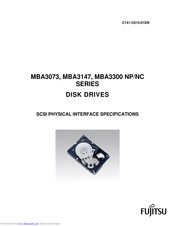
Fujitsu MBA3300 NP SERIES Technical Manual (209 pages)
DISK DRIVES SCSI PHYSICAL INTERFACE SPECIFICATIONS
Table of Contents
Advertisement

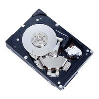
Fujitsu MBA3300 NP SERIES Product Manual (138 pages)
Fujitsu Computer Drive User Manual
Table of Contents
Advertisement

Fujitsu MBA3300 NP SERIES Installation Manual (2 pages)
HARD DISK DRIVES
Brand: Fujitsu
|
Category: CD/CDR Drive
|
Size: 0 MB
Table of Contents
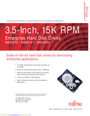
Fujitsu MBA3300 NP SERIES Specification (2 pages)
3.5-Inch, 15K RPM Enterprise Hard Disk Drives
Advertisement