Fujitsu MBA3073NC Manuals
Manuals and User Guides for Fujitsu MBA3073NC. We have 5 Fujitsu MBA3073NC manuals available for free PDF download: Product Manual, Specification, Installation Manual

Advertisement
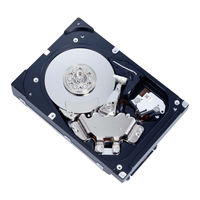

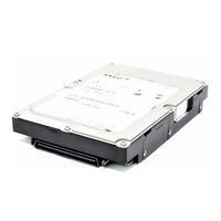
Fujitsu MBA3073NC Installation Manual (2 pages)
HARD DISK DRIVES
Brand: Fujitsu
|
Category: CD/CDR Drive
|
Size: 0 MB
Table of Contents
Advertisement
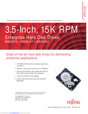
Fujitsu MBA3073NC Specification (2 pages)
3.5-Inch, 15K RPM Enterprise Hard Disk Drives
Advertisement