Sign In
Upload
Manuals
Brands
Daikin Manuals
Air Conditioner
FTXS35CVMB(9)(8)
Daikin FTXS35CVMB(9)(8) Manuals
Manuals and User Guides for Daikin FTXS35CVMB(9)(8). We have
3
Daikin FTXS35CVMB(9)(8) manuals available for free PDF download: Service Manual
Daikin FTXS35CVMB(9)(8) Service Manual (298 pages)
Super Multi NX C-Series
Brand:
Daikin
| Category:
Air Conditioner
| Size: 13.2 MB
Table of Contents
Table of Contents
3
Introduction
8
Safety Cautions
8
Caution in Repair
8
Cautions Regarding Products after Repair
9
Inspection after Repair
10
Using Icons
11
Using Icons List
11
Part 1 List of Functions
12
List of Functions
13
Cooling Only Models
13
Heat Pump Models
19
Part 2 Specifications
28
Indoor Units - Cooling Only
29
Outdoor Units - Cooling Only
41
Indoor Units - Heat Pump
47
Outdoor Units - Heat Pump
62
Part 3 Printed Circuit Board Connector Wiring Diagram
68
Printed Circuit Board Connector Wiring Diagram
69
Wall Mounted Type 20 / 25 / 35 Class
69
Pcb Detail
71
Wall Mounted Type 50 / 60 / 71 Class
72
Duct Connected Type
74
Floor / Ceiling Suspended Dual Type
75
Floor Standing Type
77
Outdoor Units
79
Part 4 Function and Control
80
Main Functions
81
Frequency Principle
81
Power-Airflow Dual Flaps, Wide Angle Louvers and Auto-Swing
83
Fan Speed Control for Indoor Units
84
Programme Dry Function
85
Automatic Operation
86
Night Set Mode
87
Intelligent Eye
88
Home Leave Operation
90
Inverter Powerful Operation
91
Other Functions
92
Function of Main Structural Parts
94
Main Structural Parts
94
Function of Thermistor
95
Heat Pump Model
95
Cooling Only Model
97
Control Specification
99
Mode Hierarchy
99
Frequency Control
100
Controls at Mode Changing / Start-Up
102
Discharge Pipe Control
103
Input Current Control
103
Freeze-Up Protection Control
104
Heating Peak-Cut Control
104
Fan Control
105
Moisture Protection Function 2
105
Defrost Control
106
Low Hz High Pressure Limit
106
Electronic Expansion Valve Control
107
Target Discharge Pipe Temperature Control
110
Sc Control
110
Malfunctions
112
Sensor Malfunction Detection
112
Insufficient Gas Control
112
Forced Operation Mode
113
Wiring-Error Check
114
Additional Function
116
Part 5 System Configuration
118
System Configuration
119
Operation Instructions
119
System Configuration Part
119
Instruction
120
Contents and Reference Page
120
Safety Precautions
121
Installation Site
122
Electrical Work
122
Names of Parts
123
Indoor Unit
124
Remote Control
134
Preparation before Operation
135
To Set the Clock
137
AUTO · DRY · COOL · HEAT · FAN Operation
138
To Change the Air Flow Rate Setting
139
Adjusting the Air Flow Direction
140
POWERFUL Operation
146
OUTDOOR UNIT SILENT Operation
147
HOME LEAVE Operation
148
INTELLIGENT EYE Operation
150
TIMER Operation
154
To Use on Timer Operation
155
To Combine on Timer and off Timer
155
Note for Multi System
156
Priority Room Setting
157
Care and Cleaning
158
Air Filter
159
Before a Long Idle Period
160
Front Grille
161
Troubleshooting
168
Check Again
169
Call the Service Shop Immediately
170
Part 6 Service Diagnosis
172
Caution for Diagnosis
173
Troubleshooting with the Operation Lamp
173
Problem Symptoms and Measures
175
Service Check Function
176
Code Indication on the Remote Controller
177
Error Codes and Description of Fault
177
Troubleshooting
178
Indoor Units
178
Outdoor Units
179
Indoor Unit PCB Abnormality
180
Freeze-Up Protection Control or High Pressure Control
181
Fan Motor or Related Abnormality
183
Ac Motor
183
DC Motor
184
Thermistor or Related Abnormality (Indoor Unit)
186
Shutter Drive Motor / Shutter Limit Switch Abnormality
187
Signal Transmission Error (between Indoor and Outdoor Units)
188
Unspecified Voltage (between Indoor and Outdoor Units)
189
Freeze-Up Protection Control
190
OL Activation (Compressor Overload)
192
Compressor Lock
193
DC Fan Lock
194
Input over Current Detection
195
Four Way Valve Abnormality
197
Discharge Pipe Temperature Control
199
Position Sensor Abnormality
200
CT or Related Abnormality
201
Thermistor or Related Abnormality (Outdoor Unit)
203
Electrical Box Temperature Rise
205
Radiation Fin Temperature Rise
207
Output over Current Detection
209
Insufficient Gas
211
Low-Voltage Detection
213
Anti-Icing Function in Other Rooms / Unspecified Voltage (between Indoor and Outdoor Units)
214
Check
215
How to Check
215
Electronic Expansion Valve Check
216
Four Way Valve Performance Check
217
Thermistor Resistance Check
218
Installation Condition Check
219
Discharge Pressure Check
220
Power Supply Waveforms Check
221
Inverter Units Refrigerant System Check
221
Capacitor Voltage Check
222
Power Transistor Check
222
Main Circuit Electrolytic Capacitor Check
223
Hall IC Check
224
Part 7 Removal Procedure
226
Outdoor Unit (80 / 90 Class)
227
Removal of Outer Panels
227
Removal of Propeller Fans
230
Removal of Electrical Box
231
Removal of PCB
238
Removal of Fan Motor
241
Removal of Electronic Expansion Valve and Thermistor
243
Removal of Sound Insulation and Reactor
244
Removal of Shunt
246
Removal of Solenoid Valve and Four Way Valve
247
Removal of Compressor
249
Outdoor Unit (50 / 52 / 58 / 68 / 75 Class)
251
Removal of Outer Panels
251
Removal of Electrical BOX
252
Removal of PCB
256
Removal of Fan Motor
259
Removal of Sound Insulation
260
Removal of Four Way Valve Coil, Solenoid Valve Coil, Electronic Expansion Valve Coil and Thermistor
261
Removal of Four Way Valve, Solenoid Valve and Shunt
263
Removal of Solenoid Valve and Shunt
264
Removal of Compressor
265
Part 8 Others
266
Others
267
Test Run from the Remote Controller
267
Jumper Settings
268
Part 9 Appendix
270
Piping Diagrams
271
Indoor Units
271
Outdoor Units
277
Heat Pump
282
Wiring Diagrams
284
Indoor Units
284
Outdoor Units
287
Advertisement
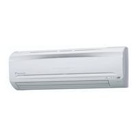
Daikin FTXS35CVMB(9)(8) Service Manual (248 pages)
Inverter Pair Wall Mounted Type C-Series D-Series
Brand:
Daikin
| Category:
Air Conditioner
| Size: 15.34 MB
Table of Contents
Wall Mounted Type
1
Table of Contents
3
Introduction
6
Safety Cautions
6
Caution in Repair
6
Cautions Regarding Products after Repair
7
Inspection after Repair
8
Using Icons
9
Using Icons List
9
Part 1 List of Functions
10
List of Functions Part
10
List of Functions
11
High Grade Models
11
Standard Grade Models
13
Non-Lnverter Models
16
Part 2 Specifications
18
Specifications
19
Cooling Only
19
Heat Pump
25
Part 3 Printed Circuit Board Connector Wiring Diagram
38
Printed Circuit Board Connector Wiring Diagram
39
Indoor Unit
39
Outdoor Unit / ARK(X)S-C
41
Outdoor Unit / RK(X)H-C, ARK(X)H-C, R(Y)N-C
43
Part 4 Function and Control
44
Main Functions
45
Frequency Principle
45
Power-Airflow Dual Flaps, Wide-Angle Louvres and Auto-Swing
47
Fan Speed Control for Indoor Units
48
Programme Dry Function
49
Automatic Operation
50
NIGHT SET Mode
51
Intelligent Eye
52
HOME LEAVE Operation
54
Inverter POWERFUL Operation
55
Other Functions
56
Function of Thermistor
57
Heat Pump Model
57
Cooling Only Model
58
Control Specification
59
Mode Hierarchy
59
Frequency Control
60
Controls at Mode Changing / Start-Up
62
Discharge Pipe Control
63
Input Current Control
64
Freeze-Up Protection Control
64
Heating Peak-Cut Control
65
Fan Control
65
Liquid Compression Protection Function 2
65
Defrost Control
66
Electronic Expansion Valve Control
67
Target Discharge Pipe Temperature Control
69
Malfunctions
70
Forced Operation Mode
71
Additional Function
71
Facility Setting Jumper (Cooling at Low Outdoor Temperature)
72
Part 5 System Configuration
74
System Configuration
75
Instruction
76
Safety Precautions
76
Installation Site
77
Electrical Work
77
Names of Parts
78
Outdoor Unit
79
Remote Control
80
Preparation before Operation
81
To Set the Clock
83
Auto Dry Cool Heat Fan Operation
84
To Change the Air Flow Rate Setting
85
Adjusting the Air Flow Direction
86
POWERFUL Operation
88
OUTDOOR UNIT SILENT Operation
89
HOME LEAVE Operation
90
INTELLIGENT EYE Operation
92
TIMER Operation
94
To Use on Timer Operation
95
To Combine on Timer and off Timer
95
Care and Cleaning
96
Air Filter
97
Before a Long Idle Period
98
Troubleshooting
99
Part 6 Service Diagnosis
104
Caution for Diagnosis
105
Problem Symptoms and Measures
106
Service Check Function
107
Troubleshooting
110
Error Codes and Description
110
Indoor Unit PCB Abnormality
111
Freeze-Up Protection Control or High Pressure Control
112
Fan Motor (AC Motor) or Related Abnormality
114
Thermistor or Related Abnormality (Indoor Unit)
115
Signal Transmission Error (between Indoor and Outdoor Unit)
116
OL Activation (Compressor Overload)
117
Compressor Lock
118
DC Fan Lock
119
Input over Current Detection
120
Four Way Valve Abnormality
121
Discharge Pipe Temperature Control
123
High Pressure Control in Cooling
124
Position Sensor Abnormality
126
DC Voltage / Current Sensor Abnormality
127
Thermistor or Related Abnormality (Outdoor Unit)
128
Electrical Box Temperature Rise
130
Radiation Fin Temperature Rise
132
Output over Current Detection
134
Insufficient Gas
136
Over-Voltage Detection
138
Check
139
How to Check
139
Four Way Valve Performance Check
140
Thermistor Resistance Check
141
Installation Condition Check
142
Discharge Pressure Check
142
Outdoor Unit Fan System Check
143
Power Supply Waveforms Check
144
Inverter Units Refrigerant System Check
144
Power Transistor Check
145
Hall IC Check
146
Part 7 Removal Procedure
148
Indoor Unit
149
Removal of Air Filter
149
Removal of Front Grille
152
Removal of Horizontal Blade and Vertical Blade
155
Removal of Switch Box, PC Board and Swing Motor
157
Removal of Heat Exchanger
163
Install of Drain Plug
166
Removal of Fan Rotor and Fan Motor
167
Outdoor Unit / ARK(X)S-C
171
Removal of Panels and Fan Motor
171
Removal of Electrical Box
178
Removal of Reactor and Partition Plate
180
Removal of Sound Blanket
182
Removal of Four Way Valve
184
Removal of Compressor
186
Removal of PCB
188
Outdoor Unit / RK(X)H-C, ARK(X)H-C, R(Y)N-C
191
Removal of External Panels
191
Removal of Bell Mouth
194
Removal of PCB
195
Removal of Electrical Box
203
Removal of Propeller Fan and Fan Motor
206
Removal of Compressor Sound Insulation Pad
209
Removal of Compressor
218
Removal of Four Way Valve
221
Removal of Electronic Expansion Valve
224
Part 8 Others
226
Others
227
Test Run from the Remote Control
227
Jumper Settings
228
Part 9 Appendix
230
Piping Diagrams
231
Indoor Units
231
Outdoor Units
232
Wiring Diagrams
238
Indoor Units
238
Outdoor Units
239
Index
242
Drawings & Flow Charts
246
Daikin FTXS35CVMB(9)(8) Service Manual (230 pages)
Inverter Multi for 2 Rooms
Brand:
Daikin
| Category:
Air Conditioner
| Size: 6.28 MB
Table of Contents
Table of Contents
3
Introduction
6
Safety Cautions
6
Part 1 List of Functions
10
Cooling Only
11
Heat Pump
13
Part 2 Specifications
16
Cooling Only
17
Indoor Units
17
Outdoor Units
21
Heat Pump
23
Indoor Units
23
Outdoor Units
27
Part 3 Printed Circuit Board Connector Wiring Diagram
30
Printed Circuit Board Connector Wiring Diagram
31
Wall Mounted Type
31
Duct Connected Type
36
Floor / Ceiling Suspended Dual Type
38
Outdoor Unit
40
Part 4 Function and Control
42
Main Functions
43
Frequency Principle
43
Power-Airflow Dual Flaps, Wide Angle Louvers and Auto-Swing
45
Fan Speed Control for Indoor Units
46
Programme Dry Function
47
Automatic Operation
48
Thermostat Control
49
Night Set Mode
50
ECONO Mode
51
Intelligent Eye
52
HOME LEAVE Operation
54
Inverter POWERFUL Operation
55
Other Functions
56
Function of Main Structural Parts
58
Main Structural Parts
58
Function of Thermistor
59
Control Specification
62
Mode Hierarchy
62
Frequency Control
63
Controls at Mode Changing / Start-Up
66
Discharge Pipe Control
67
Input Current Control
67
Freeze-Up Protection Control
68
Heating Peak-Cut Control
68
Fan Control
69
Liquid Compression Protection Function 2
69
Defrost Control
70
Electronic Expansion Valve Control
71
3.12 Malfunctions
75
Forced Operation Mode
76
3.14 Additional Function
77
Part 5 System Configuration
78
System Configuration
79
Instruction
80
Manual Contents and Reference Page
80
Safety Precautions
81
Names of Parts
83
Preparation before Operation
95
AUTO · DRY · COOL · HEAT · FAN Operation
98
Adjusting the Air Flow Direction
100
POWERFUL Operation
106
OUTDOOR UNIT SILENT Operation
107
ECONO Operation
108
HOME LEAVE Operation
109
INTELLIGENT EYE Operation
111
TIMER Operation
115
Note for Multi System
117
Care and Cleaning
119
Troubleshooting
130
Part 6 Service Diagnosis
136
Caution for Diagnosis
137
Problem Symptoms and Measures
139
Service Check Function
140
Troubleshooting
143
Error Codes and Description
143
Indoor Unit PCB Abnormality
144
Freeze-Up Protection Control or High Pressure Control
145
Fan Motor or Related Abnormality
147
Thermistor or Related Abnormality (Indoor Unit)
150
Freeze-Up Protection Control
151
OL Activation (Compressor Overload)
153
Compressor Lock
154
DC Fan Lock
155
Input over Current Detection
156
Four Way Valve Abnormality
158
Discharge Pipe Temperature Control
160
High Pressure Control in Cooling
161
Position Sensor Abnormality
163
CT or Related Abnormality
164
Thermistor or Related Abnormality (Outdoor Unit)
166
Electrical Box Temperature Rise
168
Radiation Fin Temperature Rise
170
Output over Current Detection
172
Insufficient Gas
174
Over-Voltage Detection
176
Anti-Icing Function in Other Rooms / Unspecified Voltage (between Indoor and Outdoor Units)
177
Outdoor Unit PCB Abnormality or Signal Transmission Circuit Abnormality
178
Check
179
How to Check
179
Part 7 Removal Procedure
188
Outdoor Unit
189
Removal of the Panels / Fan Motor
189
Removal of the PCB
194
Removal of the Electrical Box
199
Removal of the Sound Blanket
202
Removal of the Thermistor
205
Removal of the Four Way Valve
206
Removal of the Electronic Expansion Valve
208
Removal of the Compressor
209
Part 8 Others
212
Others
213
Test Run from the Remote Controller
213
Jumper Settings
214
Part 9 Appendix
216
Piping Diagrams
217
Indoor Units
217
Outdoor Units
219
Wiring Diagrams
220
Indoor Units
220
Outdoor Units
222
Index
224
Advertisement
Advertisement
Related Products
Daikin FTXS35CVMB
Daikin FTXS35CAVMB
Daikin FTXS35CVMB9
Daikin FTXS35CVMB8
Daikin FTXS35BVMA
Daikin FTXS35D2VMWL
Daikin FTXS35DAVMW(L)
Daikin FTXS35D3VMW(L)
Daikin FTXS35D2(3)VMW(L)
Daikin FTXS35JV2CN
Daikin Categories
Air Conditioner
Heat Pump
Remote Control
Chiller
Fan
More Daikin Manuals
Login
Sign In
OR
Sign in with Facebook
Sign in with Google
Upload manual
Upload from disk
Upload from URL