Sign In
Upload
Manuals
Brands
Beckhoff Manuals
Measuring Instruments
EL3692
Beckhoff EL3692 Manuals
Manuals and User Guides for Beckhoff EL3692. We have
2
Beckhoff EL3692 manuals available for free PDF download: Manual, Documentation
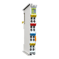
Beckhoff EL3692 Documentation (162 pages)
2 channel resistance measurement terminal
Brand:
Beckhoff
| Category:
Measuring Instruments
| Size: 5.96 MB
Table of Contents
Table of Contents
3
1 Foreword
5
Notes on the Documentation
5
Safety Instructions
6
Documentation Issue Status
7
Version Identification of Ethercat Devices
7
Fig. 1 EL5021 el Terminal, Standard IP20 IO Device with Batch Number and Revision ID (Since 2014/01)
9
Fig. 2 EK1100 Ethercat Coupler, Standard IP20 IO Device with Batch Number
9
Fig. 3 CU2016 Switch with Batch Number
9
Fig. 4 EL3202-0020 with Batch Numbers 26131006 and Unique ID-Number 204418
10
Fig. 5 EP1258-00001 IP67 Ethercat Box with Batch Number 22090101 and Unique Serial Number 158102
10
Fig. 6 EP1908-0002 IP76 Ethercat Safety Box with Batch Number 071201FF and Unique Serial Number 00346070
10
Fig. 7 EL2904 IP20 Safety Terminal with Batch Number/Date Code 50110302 and Unique Serial Num- Ber 00331701
10
2 Product Overview
11
Introduction
11
Technology
11
Fig. 9 Principle of Operation
12
Technical Data
13
Start
13
3 Basics Communication
14
Ethercat Basics
14
Ethercat Cabling - Wire-Bound
14
General Notes for Setting the Watchdog
15
Fig. 10 System Manager Current Calculation
15
Fig. 11 Ethercat Tab -> Advanced Settings -> Behavior -> Watchdog
16
Ethercat State Machine
17
Fig. 12 States of the Ethercat State Machine
18
Coe Interface
19
General Description
19
Fig. 13 "Coe Online " Tab
20
Fig. 14 Startup List in the Twincat System Manager
21
Fig. 15 Offline List
22
Fig. 16 Online List
23
Distributed Clock
24
4 Installation
25
Installation on Mounting Rails
25
Fig. 17 Attaching on Mounting Rail
25
Fig. 18 Disassembling of Terminal
26
Installation Instructions for Enhanced Mechanical Load Capacity
27
Fig. 19 Power Contact on Left Side
27
Connection System
28
Fig. 20 Standard Wiring
28
Fig. 21 Pluggable Wiring
29
Fig. 22 High Density Terminals
29
Fig. 23 Mounting a Cable on a Terminal Connection
30
Installation Positions
31
Fig. 24 Recommended Distances for Standard Installation Position
31
Mounting of Passive Terminals
32
Fig. 25 Other Installation Positions
32
Fig. 26 Correct Configuration
33
Fig. 27 Incorrect Configuration
33
Leds and Connection
34
Fig. 8 EL3692
34
Fig. 28 Connection Diagram
34
Electrical Connection
35
Fig. 29 Connection
35
Fig. 30 Connection Options
36
5 Commissioning
37
Twincat Quick Start
37
Fig. 31 Relationship between User Side (Commissioning) and Installation
38
Fig. 32 Control Configuration with an Embedded PC and Input (EL1004) and Output (EL2008)
39
Fig. 33 Initial Twincat 2 User Interface
39
Fig. 34 Selection of the Target System
40
Fig. 35 Specify the PLC for Access by the Twincat System Manager: Selection of the Target System
40
Fig. 36 Select "Scan Devices
41
Fig. 37 Automatic Detection of I/O Devices: Selection the Devices to be Integrated
41
Fig. 38 Mapping of the Configuration in the Twincat 2 System Manager
42
Fig. 39 Reading of Individual Terminals Connected to a Device
42
Fig. 40 Twincat PLC Control after Startup
43
Fig. 41 Sample Program with Variables after a Compile Process (Without Variable Integration)
44
Twincat 2
61
Twincat 3
61
Twincat Development Environment
61
Installation of the Twincat Real-Time Driver
61
Notes Regarding ESI Device Description
67
Twincat ESI Updater
71
Distinction between Online and Offline
71
OFFLINE Configuration Creation
72
ONLINE Configuration Creation
77
Troubleshooting
81
Ethercat Subscriber Configuration
85
General Notes - Ethercat Slave Application
95
Fig. 132 PLC Function Blocks
101
Fig. 133 Illegally Exceeding the E-Bus Current
102
Fig. 134 Warning Message for Exceeding E-Bus Current
102
Quick Start
103
Fig. 135 Connection Examples
104
Fig. 136 EL3692 Representation in the Twincat System Manager
105
Operating Behavior, Diagnostics
106
Control
106
Basic Operation
107
Default State
107
Process Data
107
4/2-Wire Mode
107
Measuring Mode
108
Autorange Function
109
Filter
109
Conversion Time
110
Fig. 137 Filter Characteristic
110
Error Codes
111
Process Data
111
Fig. 138 Screenshot of System Manager, Process Data
112
Fig. 139 Selection Dialog Predefined PDO
113
Specific Data
115
Measuring Currents and Voltages
115
Capacitive and Inductive Influences
116
Heating of the Test Specimen
116
Calculating the Resistance Value
116
Error Analysis
118
Fig. 140 Max. Absolute Measuring Error for each Measuring Range, Full Logarithmic Diagram
118
Resolution
119
Data Processing
119
Fig. 141 Calculated Maximum Relative Measuring Error Relative to the Current Measured Value in the Re- Spective Measuring Range
119
Fig. 142 Measurement Sequence
119
Measurement Sequence
120
DC Operation Mode
121
Notices on Analog Specifications
121
Fig. 143 Data Processing Sequence
121
Fig. 144 Full Scale Value, Measuring Span
122
Fig. 145 SE and DIFF Module as 2-Channel Version
124
Fig. 146 2-Wire Connection
126
Fig. 147 Connection of Externally Supplied Sensors
127
Fig. 148 2-, 3- and 4-Wire Connection at Single-Ended and Differential Inputs
128
Example Program
129
Fig. 149 Example Program
129
Fig. 150 Find MAC Address
130
Fig. 151 Searching the Ethernet Adapter
130
Fig. 152 Selection and Confirmation of the Ethernet Adapter
131
Fig. 153 Activation of the Configuration
131
Fig. 154 Confirming the Activation of the Configuration
131
Fig. 155 Generating Variable Mapping
131
Fig. 156 Restarting Twincat in RUN Mode
131
Coe
132
Most Important Coe Entries
132
Fig. 157 Compile Project
132
Fig. 158 Confirming Program Start
132
Object Description and Parameterization
134
Fig. 159 Offset Value Per Measuring Range for User Calibration
134
Restore Object
135
Configuration Data
136
Input Data
137
Output Data
138
Configuration Data (Vendor-Specific)
138
Information and Diagnostic Data
138
Standard Objects (0X1000-0X1Fff)
139
6 Appendix
144
Ethercat al Status Codes
144
UL Notice
144
Firmware Update El/Es/Em/Epxxxx
146
Fig. 160 Device Identifier Consisting of Name EL3204-0000 and Revision -0016
147
Fig. 161 Scan the Subordinate Field by Right-Clicking on the Ethercat Device in Config/Freerun Mode . 148 Fig. 162 Configuration Is Identical
148
Fig. 163 Change Dialog
148
Fig. 164 EEPROM Update
149
Fig. 165 Selecting the New ESI
149
Fig. 166 Display of EL3204 Firmware Version
150
Fig. 167 Firmware Update
151
Fig. 168 FPGA Firmware Version Definition
152
Fig. 169 Context Menu Properties
152
Fig. 170 Dialog Advanced Settings
153
Fig. 171 Select Dialog Advanced Settings
154
Fig. 172 Select Dialog Write FPGA
154
Fig. 173 Select File
155
Fig. 174 Multiple Selection and Firmware Update
155
Firmware Compatibility
156
Restoring the Delivery State
156
Fig. 175 Selecting the "Restore Default Parameters" PDO
157
Fig. 176 Entering a Restore Value in the Set Value Dialog
157
Support and Service
158
List of Illustrations
159
Advertisement
Beckhoff EL3692 Manual (193 pages)
2 Channel Resistance Measurement Terminal, high-precision
Brand:
Beckhoff
| Category:
Measuring Instruments
| Size: 8.95 MB
Table of Contents
Table of Contents
3
Foreword
7
Notes on the Documentation
7
Safety Instructions
8
Documentation Issue Status
9
Version Identification of Ethercat Devices
10
General Notes on Marking
10
Version Identification of el Terminals
11
Beckhoff Identification Code (BIC)
12
Electronic Access to the BIC (Ebic)
14
Product Description
16
Introduction
16
Technology
17
Technical Data
19
Note on Beckhoff Calibration Certificates
20
Start
22
Basics Communication
23
Ethercat Basics
23
Ethercat Cabling - Wire-Bound
23
General Notes for Setting the Watchdog
24
Ethercat State Machine
26
Coe Interface
28
Distributed Clock
33
Installation
34
Instructions for ESD Protection
34
Explosion Protection
35
ATEX - Special Conditions (Standard Temperature Range)
35
Continuative Documentation for ATEX and Iecex
36
UL Notice
37
Installation on Mounting Rails
38
Installation Instructions for Enhanced Mechanical Load Capacity
41
Connection
42
Connection System
42
Wiring
44
Shielding
45
Installation Positions
46
Leds and Connection
48
Electrical Connection
50
4.10 Positioning of Passive Terminals
52
4.11 Disposal
53
Commissioning
54
Twincat Quick Start
54
Twincat 2
57
Twincat 3
67
Twincat Development Environment
80
Installation of the Twincat Real-Time Driver
81
Notes Regarding ESI Device Description
87
Twincat ESI Updater
91
Distinction between Online and Offline
91
OFFLINE Configuration Creation
92
ONLINE Configuration Creation
97
Ethercat Subscriber Configuration
105
General Commissioning Instructions for an Ethercat Slave
114
Notices on Analog Specifications
122
Full Scale Value (FSV), Output End Value
122
Measurement Error/Measurement Deviation/Measurement Uncertainty, Output Uncertainty
123
Temperature Coefficient Tk [Ppm/K]
124
Long-Term Use
125
Ground Reference: Single-Ended/Differential Typification
126
Common-Mode Voltage and Reference Ground (Based on Differential Inputs)
131
Dielectric Strength
132
Temporal Aspects of Analog/Digital or Digital/Analog Conversion
133
Explanation of the Term Gnd/Ground
136
Sampling Type: Simultaneous Vs. Multiplexed
138
Quick Start
141
Operating Behavior, Diagnostics
144
Control
144
Basic Operation
144
Default State
144
Process Data
144
4/2-Wire Mode
144
Measuring Mode
145
Autorange Function
146
Filter
146
Conversion Time
147
Error Codes
148
Process Data
149
Specific Data
153
Measuring Currents and Voltages
153
Capacitive and Inductive Influences
153
Heating of the Test Specimen
153
Calculating the Resistance Value
154
Error Analysis
155
Resolution
156
Data Processing
157
5.10 DC Operation Mode
160
5.11 Example Program
161
5.12 Coe
165
Most Important Coe Entries
165
Object Description and Parameterization
167
Restore Object
168
Configuration Data
168
Input Data
169
Output Data
170
Configuration Data (Vendor-Specific)
170
Information and Diagnostic Data
170
Standard Objects (0X1000-0X1Fff)
171
Appendix
176
Ethercat al Status Codes
176
Firmware Compatibility
177
Firmware Update El/Es/Em/Elm/Epxxxx
178
Device Description ESI File/Xml
179
Firmware Explanation
182
Updating Controller Firmware *.Efw
183
FPGA Firmware *.Rbf
185
Simultaneous Updating of Several Ethercat Devices
189
Restoring the Delivery State
190
Support and Service
191
Advertisement
Related Products
Beckhoff EL3681
Beckhoff EP3744-0041
Beckhoff EP3744-1041
Beckhoff EJ3255
Beckhoff EPP3752-0000
Beckhoff EPP3504-0023
Beckhoff EP6070-0060
Beckhoff EP3751-0160
Beckhoff EL3632
Beckhoff EL3356-0010
Beckhoff Categories
Touch terminals
Industrial PC
Control Unit
Touch Panel
Power Supply
More Beckhoff Manuals
Login
Sign In
OR
Sign in with Facebook
Sign in with Google
Upload manual
Upload from disk
Upload from URL