AUMA SARV 16.2 Manuals
Manuals and User Guides for AUMA SARV 16.2. We have 5 AUMA SARV 16.2 manuals available for free PDF download: Operation Instructions Manual, Manual, Assembly Instructions
AUMA SARV 16.2 Operation Instructions Manual (92 pages)
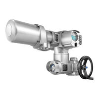
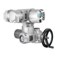
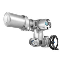
Multi-turn actuators
Brand: AUMA
|
Category: Controller
|
Size: 2 MB
Table of Contents
Advertisement
AUMA SARV 16.2 Operation Instructions Manual (96 pages)
Multi-turn actuators
Brand: AUMA
|
Category: Controller
|
Size: 2 MB
Table of Contents

AUMA SARV 16.2 Operation Instructions Manual (92 pages)
Multi-turn actuators Control unit: electronic (MWG) with actuator controls ACV 01.2 Non-Intrusive Multiport valve version
Brand: AUMA
|
Category: Controller
|
Size: 5 MB
Table of Contents
Advertisement
AUMA SARV 16.2 Manual (24 pages)
Multi-turn actuators with actuator controls SFC version
Brand: AUMA
|
Category: Controller
|
Size: 1 MB
Table of Contents

AUMA SARV 16.2 Assembly Instructions (3 pages)
Square head for pit application
Brand: AUMA
|
Category: Controller
|
Size: 0 MB
Advertisement