Sign In
Upload
Manuals
Brands
Ametek Manuals
Control Unit
UPLC-II
Ametek UPLC-II Manuals
Manuals and User Guides for Ametek UPLC-II. We have
1
Ametek UPLC-II manual available for free PDF download: System Manual
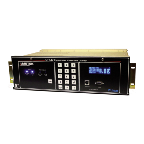
Ametek UPLC-II System Manual (200 pages)
Universal Power-Line Carrier
Brand:
Ametek
| Category:
Control Unit
| Size: 9.53 MB
Table of Contents
Table of Contents
3
Table of Contents
6
1 Ordering Information
9
UPLC-II™ Catalog Number Digits Explanation
11
2 Product Description
13
Specifications
13
Applications
15
Standard Nomenclature
17
UPLC-II™ Chassis
17
UPLC-II™ Modules
17
Power Supply Module
22
Power Amp Module
24
Display Module
26
Input/Output (I/O) Module
28
Transceiver Module
30
Ethernet Module
32
UPLC-II™ Functional Description
36
Keying Input Logic
37
Receiver Output Logic
41
3 Applications
47
ON/OFF Mode Protective Relay Applications
47
Directional-Comparison Blocking (DCB)
47
Phase-Comparison Blocking
47
ON/OFF Mode Special Considerations
53
ON/OFF Mode Typical Wiring/Connections
53
ON/OFF Mode Alarms
60
FSK Mode Protective Relay Applications
62
Directional Comparison Unblocking
62
Permissive Overreaching Transfer Trip Systems
64
Permissive and Non-Permissive Underreaching Transfer Trip Systems
64
Dual Phase Comparison Unblocking Systems
64
Segregated Phase Comparison System
67
Direct Transfer-Trip (DTT) Systems
72
Transformer Protection
72
Shunt Reactor Protection
72
Remote Breaker-Failure Protection
72
Direct Transfer Trip Channel Considerations
73
FSK Mode Special Considerations
74
3-Freq. Systems
75
Directional Comparison Unblocking (2-Frequency)
75
Transfer Trip: Overreaching, Underreaching or Direct (2-Frequency)
76
Phase Comparison Unblocking: Dual or Segregated (2-Frequency)
76
FSK Mode Typical Wiring/Connections
76
FSK Mode Alarms
83
Hybrid Applications
85
Examples
86
4 Test Equipment, Maintenance & Troubleshooting
89
Recommended Test Equipment
89
Periodic Checks
90
Trouble Detection Sequence
90
Front Display Alarms
90
Test Equipment, Maintenance & Troubleshooting
91
Transceiver NOVRAM Battery
92
5 Installation/Commissioning Procedure
93
Quick Installation Guide
93
Introduction
95
Safety Precautions
95
Mounting & Connecting the Unit
95
Mounting
95
Terminal Block Connections
95
Equipment Ground
95
RF Coax Connections
97
Other Connections
98
Hardware Jumper Settings
98
I/O Module
99
Backplane (Rear Panel)
99
Power Supply Module
100
Aux. Power Supply Module (for Driving EM Protective Relays)
100
Power Amplifier Module
100
PC Setup for Communication with the UPLC-II
102
Ethernet Port - PC/UPLC-II™ Setup
102
Front RS-232 Port - PC Setup
103
Logging in
103
Admin Web Page
105
User Accounts
105
Making/Saving Settings
106
Loading Settings
106
Saving Settings
106
Working Vs Temporary Settings
108
Settings
108
General Tab
109
Logic Tab
112
Input/Output Tab
115
Checkback (ON/OFF Mode) or Trip Test (FSK Mode) Tab
122
RF Configuration Tab
122
Submit Tab
122
Testing Facilities
122
Calibration
123
SOE Log
124
Home Page
126
Front Panel
128
Password Access
128
Front Panel Display
128
Set Button Menu
128
Test Button Menu
129
6 Testing Facilities
131
Checkback Test Facility (Quick Checklist, if Not Working)
131
ON/OFF Mode Automatic Checkback (CB) Feature
131
General Description
131
Checkback (CB) Settings
132
General Information
132
Primary Communications Mode
132
Checkback Test Sequence
132
Last Remote
133
Auto Tests
133
Low Power Tests
133
Retries
133
Automatic Tests - Time Settings
133
Optional Carrier Recovery
134
Checkback Tester Inputs/Outputs
136
Performing Checkback Tests/Functions
137
Manual Requests from Web
137
Loopback Test Capability (Turn on Remote Transmitter Via the Power Line)
137
Remote-Initiated Periodic Tests
138
Remote-Initiated "Hours of the Day" Tests
138
System Troubleshooting with Checkback
139
FSK Mode Trip Test Feature
143
General Description
143
Two Frequency Applications Real Trip Scenario
143
Two Frequency Application Checkback Trip Scenario
143
Three Frequency Applications Checkback Trip Scenario
143
Trip Test Initiation
144
Trip Test Pulse
144
7 Communication Protocols
149
Dnp 3
149
DNP Binary Inputs (UPLC-II™ Inputs)
151
DNP Binary Inputs(UPLC-II™ Outputs)
152
DNP Analog Inputs (UPLC-II™ Analog Values)
155
IEC 61850 Protocol
156
UPLC-II™ with IEC 61850
156
Private GOOSE Subscription Details
158
Overview
159
Appendix A: UPLC-II™ Serial Connection Configuration
165
Appendix B: PC Setting for Static IP Address
169
Appendix C: UPLC-II™ XML File Format
171
Appendix D: User Management Interface (UMI
179
Appendix E: Sequence of Events (SOE) Listing
189
Appendix F: Changing the Cat. No. on a UPLC-II
195
Appendix G: Upgrading the Firmware in a UPLC-II
197
Index
199
Advertisement
Advertisement
Related Products
Ametek Surgex UPS-17202-53R
Ametek Surgex UPS-17302-60R
Ametek Surgex UPS-17602-52R
Ametek UPS-I000-OL
Ametek UPS-BPX-1000
Ametek UPS-2000-OL
Ametek UPS-3000-OL
Ametek UPS-BPX-2000
Ametek UPS-BPX-3000
Ametek SurgeX UPS-1440-Li-ISO
Ametek Categories
Measuring Instruments
Test Equipment
Power Supply
Controller
Laboratory Equipment
More Ametek Manuals
Login
Sign In
OR
Sign in with Facebook
Sign in with Google
Upload manual
Upload from disk
Upload from URL