Sign In
Upload
Manuals
Brands
Ametek Manuals
Measuring Instruments
BARBEN ANALYTICAL OXY visor
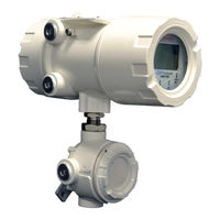
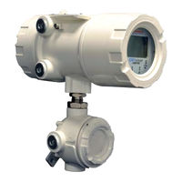
Ametek BARBEN ANALYTICAL OXY visor Manuals
Manuals and User Guides for Ametek BARBEN ANALYTICAL OXY visor. We have
2
Ametek BARBEN ANALYTICAL OXY visor manuals available for free PDF download: Installation, Operation & Maintenance Manual, Installation, Operation And Maintenance Manual
Ametek BARBEN ANALYTICAL OXY visor Installation, Operation & Maintenance Manual (84 pages)
Optical Oxygen Analyzer for use with BOSx Optical Sensors
Brand:
Ametek
| Category:
Analytical Instruments
| Size: 11 MB
Table of Contents
Intellectual Property & Copyright Notice
2
Disclaimer
2
Table of Contents
3
Section 1 - General Information & Safety
9
Introduction
9
About the Oxyvisor Product - (Overview)
9
Definition of Symbols
10
Safety Summary
11
Electrical Safety
11
1�4�2 Grounding
11
General Installation Precautions
11
Section 2 - Technical Product Specifications - RATINGS
12
12
Oxyvisor - BOA Oxygen Analyzer Specifications
12
BOS Sensor Technical Performance Specifications (Determines Operating Range for Oxyvisor)
13
Oxyvisor Configuration - Product Model Selection
14
2�4 Oxyvisor Accessories
14
General Principle of Operation
15
Figure 1 - Light Transmission
15
Figure 2 - O Quenching Intensity Vs Time
15
Figure 3 - O Quenching AC Modulation
15
Oxyvisor Analyzer Features (Hardware/Firmware/Software)
16
Figure 4 - Oxyvisor Overview of Hardware Features
17
Figure 5 - Oxyvisor Overall Dimensions
17
Hazardous Area Agency Certification & Markings
18
2�7�1 Zone 1 Group IIC - (Pending Final Approvals)
18
2�7�2 Zone 2 - (Pending Final Approvals)
18
2�7�3 Class I, Division 2 Groups A,B,C, & D
19
Product Label / Name Plate - (Pending Final Approvals)
19
Product Label / Name Plate Overview (Pending Final Approvals)
19
Figure 6 - Oxyvisor Product Label / Name Plate
19
Example Product Labels / Name Plate - (Pending Final Approvals)
20
Figure 7 - Examples of Oxyvisor Product Label / Name Plate
20
Declaration of Conformity - Certificate
21
Section 3 - Quick Start Guide
22
Quick Start Guide - BOS2
22
Section 4 - Installation
24
Installation Overview
24
Inspection of the Analyzer Shipment (Consignment)
24
4�3 Weight
25
Tools
25
Mounting the Analyzer
25
Orientation of the Junction Box - ONLY if NECESSARY
26
Oxyvisor - Pipe-Mount to Vertical Pipe
27
Oxyvisor - Pipe-Mount to Horizontal Pipe
27
Figure 8 - Oxyvisor Vertical Pipe Mount Examples
27
Figure 9 - Oxyvisor Horizontal Pipe Mount Example
27
Oxyvisor - Mounting Directly to Plate
28
Oxyvisor - Wall Mount Kit
28
Figure 10 - Oxyvisor Direct Mount
28
Figure 11 - Oxyvisor Optional Wall Mount Kit
28
Wiring - Power
29
Protective Ground (Earthing) Screw
29
4�6�2 AC Powered Analyzer
29
Figure 12 - Oxyvisor Protective Ground Screws
29
4�6�3 DC Powered Analyzer
30
Wiring - Input/Outputs
30
Figure 13 - AC Terminal Board - Located in Rear (Wiring) Compartment
30
Figure 14 - DC Terminal Board - Located in Rear (Wiring) Compartment
30
Electrical Entries
31
Securing the Rear (Wiring) Compartment Lid
31
Sensor Connection Options
32
BOS Sensor with Integral RTD Via J-Box
32
Figure 15 - BOS Sensor with Integral RTD through Junction Box
32
BOS Sensor with External Rtd's Via J-Box
33
BOS Sensor with External RTD Via Rear (Wiring) Compartment
33
Figure 16 - BOS Sensor and External RTD through Junction Box
33
Figure 17 - BOS Sensor and External RTD or Zone 1
33
Hazardous Area - Installation & Control Drawings
34
Zone 1 - Group IIC - 2P0345
34
Figure 18 - Zone 1 Hazloc - Installation Control DWG - 2P0345
34
Figure 19 - Zone 1 Hazloc - Installation Control DWG - 2P0345 (P.2)
35
Figure 20 - Zone 1 Hazloc - Installation Control DWG - 2P0345
36
Zone 2 - Group IIC - 2P0346
37
Figure 21 - Zone 2 Hazloc - Installation Control DWG - 2P0346 (P.1)
37
Figure 22 - Zone 2 Hazloc - Installation Control DWG - 2P0346
38
Figure 23 - Zone 2 Hazloc - Installation Control DWG - 2P0346
39
Class I, Div2 - 2P0335
40
Figure 24 - Class I DIV. 2 Hazloc - Installation Control DWG - 2P0335
40
Figure 25 - Class I DIV. 2 Hazloc - Installation Control DWG - 2P0335 (P.2)
41
Figure 26 - Class I DIV.2 Hazloc - Installation Control DWG - 2P0335
42
Section 5 - Operations
44
Operations Overview
44
HMI - Keypad Overview
44
Figure 27 - Oxyvisor HMI Keypad and LED Display
44
Main Display Viewing Options - Overview
45
Sub Menu Screens - Overview
45
Main Display - Functions and Use
46
Figure 28 - Main Display (Four Viewing Options) and Sub-Menu Options
46
Alternative Main Display Details - Functions and Use
47
Main Input / Output Display - Functions and Use
47
Main Trend Display - Functions and Use
47
Overall Menu Flowchart
48
Figure 29 - Programming Menu Flowchart
48
Sub-Menu - Measurement & Units Flowchart
50
Figure 30 - Sub-Menu Measurement & Units Flow Diagram
50
Measurement & Units Overview
51
Measurement & Units Overview - Media
51
Measurement & Units Overview - Oxygen Units
52
Measurement & Units Overview - Signal Intensity
53
Measurement & Units Overview - Oxygen Sensor Type
51
Figure 31 - Sub-Menu Calibration
54
Calibration Overview
55
Manual Cal - Single Point Calibration - (Zero Gas) Step-By-Step
56
Manual Cal - Two-Point Calibration - Step-By-Step
57
Figure 32 - Temperature Sensor - Smart Calibration
58
Figure 33 - Pressure Sensor - Smart Calibration
58
Figure 34 - Sub-Menu Input/Output Flow Menu
59
Input / Output - Overview
60
Input / Output - Analog Output (1&2)
61
Figure 35 - Sub-Menu Diagnostic Test Security Flow Menu
62
Diagnostic - Test Security - Overview
63
Diagnostic - Test Security - Firmware Upgrade
64
Figure 36 - Sub-Menu Datalogging Flow Menu
64
Sub-Menu - Error Codes
65
67
Safety Instructions
67
Service
68
Figure 37 - Installation of Junction Box
69
70
A1 - Partial Pressure of Oxygen - Gas Phase
70
71
A2 - Dissolved Oxygen
71
72
A3 - Drift and Sample Rate
72
73
Figure A.4. 38 - Autocal General Arrangement & Wiring
73
A4 - Drift and Sample Rate
73
74
A5 - Common Graphs
74
A7.2 - Configuration
75
Figure A.34 - Modbus Connection
75
A7.3 - Read Registers
76
Oxyvisor Optical Oxygen Analyzer
77
A7.4 - Communication Guide
77
A7.4.3 Configure and Trigger Test Gas Insert
78
A7.5 - Communication Examples
80
A7.5.2 Turning on Relays
81
A7.5.3 Triggering Test Gas Insert (TGI) - Remote Validation
82
A7.5.5 Remotely Start Autocal
83
Advertisement
Ametek BARBEN ANALYTICAL OXY visor Installation, Operation And Maintenance Manual (24 pages)
Brand:
Ametek
| Category:
Measuring Instruments
| Size: 5 MB
Table of Contents
Table of Contents
2
Disclaimer
2
Intellectual Property & Copyright Notice
2
1�2 about the
5
Product - (Overview)
5
Definition of Symbols
5
Introduction - Purpose of this Manual
5
Section 1 - General Information & Safety
5
Environmental Information (WEEE)
6
Safety Summary
6
Electrical Safety
6
1�4�2 Grounding
6
General Installation Precautions
6
2�1 Oxyvisor - BOA Oxygen Analyzer Specifications
7
2�3 Oxyvisor
7
Oxyvisor Oxyvisor
7
Configuration - Product Model Selection
7
BOS Sensor Overview
7
Oxyvisor
7
Section 2 - Technical Product Specifications - RATINGS
7
2�6 Oxyvisor Analyzer Features (Hardware/Firmware/Software)
8
Figure 1 - Oxyvisor Overview of Hardware Features
8
Figure 2 - Oxyvisor Overall Dimensions
8
General Principle of Operation
8
Accessories
8
Hazardous Area Agency Certification & Markings - [Recapitulation]
9
Zone 1 Group IIC with Specific Conditions of Use
9
Zone 2 Group IIC with Specific Conditions of Use
9
Class I, Division 2 Groups A,B,C
9
Product Label / Name Plate
9
Product Label / Name Plate Overview
9
Zone 1 Groups IIC - Barben Analytical | AMETEK
10
Zone 2 Groups IIC - Barben Analytical | AMETEK
10
Figure 3 - Oxyvisor Product Label / Name Plate
10
Declaration of Conformity - Certificate
11
Inspection of the Analyzer Shipment (Consignment)
12
Installation Overview
12
Mounting the Analyzer
12
Orientation of the Junction Box
12
3�5�2 Oxyvisor - Pipe-Mount to Vertical Pipe
12
3�5�3 Oxyvisor - Pipe-Mount to Horizontal Pipe
13
Section 3 - Installation
12
Tools
12
Weight
12
Wiring - Power
13
Protective Ground (Earthing) Screw
13
AC Powered Analyzer
13
Figure 5 - Oxyvisor Vertical Pipe Mount Examples
13
Figure 6 - Oxyvisor Horizontal Pipe Mount Example
13
Figure 7 - Oxyvisor Protective Ground Screws
13
DC Powered Analyzer
14
Figure 8 - AC Terminal Board - Located in Rear (Wiring) Compartment
14
Figure 9- DC Terminal Board - Located in Rear (Wiring) Compartment
14
Wiring - Input/Outputs
14
3�8 Electrical Entries
15
Securing the Rear (Wiring) Compartment Lid
15
Sensor Connection Options
15
BOS Sensor with Integral and External RTD Via J-Box
15
BOS Sensor with External RTD Via Rear (Wiring) Compartment
15
Figure 10 - BOS Sensor with Integral RTD through Junction Box
15
Figure 12 - BOS Sensor and External RTD or Zone 1
15
Figure 11 - BOS Sensor and External RTD through Junction Box
15
Hazardous Area - Installation & Control Drawings
16
Zone 1 - Group IIC - 2P0345
16
Figure 13.1 - Zone 1 Hazloc - Installation Control DWG - 2P0345 (P.1)
16
Figure 13.2 - Zone 1 Hazloc - Installation Control DWG - 2P0345 (P.2)
16
Zone 2 - Group IIC - 2P0346
17
Figure 13.3 - Zone 1 Hazloc - Installation Control DWG - 2P0345 (P.3)
17
Figure 14.1 - Zone 2 Hazloc - Installation Control DWG - 2P0346 (P.1)
17
Figure 14.2 - Zone 2 Hazloc - Installation Control DWG - 2P0346 (P.2)
18
Figure 14.3 - Zone 2 Hazloc - Installation Control DWG - 2P0346 (P.3)
18
Class I, Div2 - 2P0335
19
Figure 15.1 - Class I DIV. 2 Hazloc - Installation Control DWG - 2P0335 (P.1)
19
Figure 15.2 - Class I DIV. 2 Hazloc - Installation Control DWG - 2P0335 (P.2)
19
Figure 15.3 - Class I DIV.2 Hazloc - Installation Control DWG - 2P0335
20
Operations Overview
21
Section 4 - Operations
21
Sub-Menu - Error Codes
21
Maintenance Overview
23
Repairs
23
Safety Instructions
23
Section 5- Maintenance / Repair / Service
23
Service
23
Removing and Replacing Rear (Wiring) Compartment Lid
23
Advertisement
Related Products
Ametek BROOKFIELD RSO
Ametek BROOKFIELD DVPlus
Ametek BROOKFIELD DVNext
Ametek BROOKFIELD RST
Ametek dunkermotoren BG 62S
Ametek dunkermotoren BG 66x25 dMove
Ametek Dunkermotoren BG65Sx50 MI
Ametek Dunkermotoren BGE 6060 A EC
Ametek MAGNETROL ASME B31.3 Construction
Ametek 00135086
Ametek Categories
Measuring Instruments
Test Equipment
Power Supply
Switch
Controller
More Ametek Manuals
Login
Sign In
OR
Sign in with Facebook
Sign in with Google
Upload manual
Upload from disk
Upload from URL