Sign In
Upload
Manuals
Brands
Alcatel-Lucent Manuals
Network Router
7705 SAR-A
Alcatel-Lucent 7705 SAR-A Manuals
Manuals and User Guides for Alcatel-Lucent 7705 SAR-A. We have
1
Alcatel-Lucent 7705 SAR-A manual available for free PDF download: Installation Manual
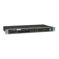
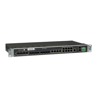
Alcatel-Lucent 7705 SAR-A Installation Manual (154 pages)
SERVICE AGGREGATION ROUTER. SAR-A Chassis
Brand:
Alcatel-Lucent
| Category:
Network Router
| Size: 1.11 MB
Table of Contents
Table of Contents
3
Preface
11
About this Guide
11
List of Technical Publications
12
Warnings and Notes
12
Preface
13
Audience
13
Information Symbols
13
Table 1 Information Symbols
13
Technical Support
14
Mandatory Regulations
15
In this Chapter
15
List of Terms
16
Table 2 List of Terms
16
Mandatory Regulations
17
General Requirements
18
Anti-Static Measures
18
Figure 1 ESD Awareness Label
18
Grounding
19
Unit Repair
20
Equipment Interconnection Points
20
SELV, Hazardous Voltage Secondary and Primary
21
Prevention of Access
21
Environmental Requirements for Installation
21
Laser Interface
21
Protective Safety Ground (Earth)
22
EMC Compliance
22
Regulatory Symbols
22
Figure 2 Protective Earth (Ground)
22
Figure 3 Earth (Ground)
23
Canada Regulations
24
Industry Canada Regulations
24
EMC Compliance
24
Safety Approval for DC Systems
25
United States Regulations
26
Federal Communications Commission
26
Nrtl
27
NRTL Approval for External DC Supplies
27
Food and Drug Administration
27
European Union Regulations
28
Declaration of Conformity
28
EU Compliance Statement
28
EMC/EMI Compliance
28
General
28
Laser Interface
29
Safety Approval for DC Systems
29
Protective Earth
29
Eco-Environmental
29
Figure 4 WEEE Symbol for Post-August 13, 2005 Product
30
Material Content Compliance
31
Australia/New Zealand Regulations
32
ACMA Regulations
32
China Regulations
33
Safety
33
Packaging Collection and Recovery Requirements
33
Material Content Compliance
33
Altitude Limit
34
Figure 5 Altitude Limit Symbol
34
7705 SAR-A Overview
35
In this Chapter
35
Overview of the 7705 SAR-A
36
7705 SAR-A Overview
37
7705 SAR-A Components
39
Chassis
39
Figure 6 Exploded View: 7705 SAR-A Chassis
40
Figure 7 Faceplate: 7705 SAR-A Chassis Variant with T1/E1 Ports
40
Figure 8 Faceplate: 7705 SAR-A Chassis Variant with no T1/E1 Ports
40
Control and Switching
41
Figure 9 7705 SAR-A Control and Switching Features
41
T1/E1 and Ethernet Ports
42
Power Supply Inputs
42
Figure 10 T1/E1 and Ethernet Ports
42
Chassis Cooling
43
7705 SAR-A System Installation Process
44
Site Preparation
45
In this Chapter
45
Warnings and Notes
46
Site Preparation
47
System Specifications
49
Chassis Specifications
49
Environmental Specifications
49
Site Preparation
49
Table 3 7705 SAR-A Chassis Specifications
49
Table 4 7705 SAR-A Environmental Specifications
49
7705 SAR-A Power Consumption
50
Table 5 Chassis Power Consumption
50
Table 6 Maximum Power Consumption for Approved Pluggable Optics
51
Table 7 Heat Dissipation
51
CBN and IBN Grounding Requirements
52
Power and Cabling Requirements
52
AC Power Requirements
53
DC Power Requirements
53
Cabling Requirements
54
Storage
54
Table 8 Storage Specifications
54
Compliance
55
Installation Locations
56
Chassis Location Requirements
57
Figure 11 Chassis Clearance Specifications
58
Table 9 Chassis Clearance Specifications
58
Installation Site Assessment
59
Geographical Location
59
Installation Site Type
60
Room
60
Cabinet
61
Site Influences
61
Seasonal Influences
62
Site Assessment Checklists
62
Table 10 Seasonal Influences
62
Local Risk Factors
63
Table 11 Local Risk Factors
63
Specific Characteristics of the Installation Site
64
Table 12 Specific Characteristics of the Installation Site
64
Installing and Grounding the Chassis
67
In this Chapter
67
Unpacking the Chassis
68
Unpacking Precautions
68
Table 13 7705 SAR-A Packing Components
69
Installing and Grounding the Chassis
69
Figure 12 Unpacking the 7705 SAR-A Chassis
69
Installing the Chassis in a Rack
70
Figure 13 Installing the 7705 SAR-A Chassis in a Rack
70
Rack-Mounting the Chassis
70
Installing and Grounding the Chassis
71
Table 14 Rack-Mounting Components
71
Chassis Ground Wiring
72
Making the Ground Connection
72
Figure 14 Preparing the Ground Wire
73
Figure 15 Attaching the Chassis Ground Connector (Cable Routed Down)
73
Table 15 Ground Wire Descriptions
73
Figure 16 Attaching the Chassis Ground Connector (Cable Routed Up)
74
Table 16 Chassis Ground Connection Components
74
DC Power Connections
75
DC Power Connections
77
In this Chapter
77
Wiring and Connecting DC Power
78
Wiring and Connecting the DC Inputs
78
Table 17 DC Power Cable Descriptions
78
Figure 17 DC Power Cable
78
DC Power Connections
79
Table 18 Wiring the DC Power Supplies Descriptions
79
Figure 18 Wiring the -48 VDC Power Supplies
79
High Voltage Power Supply Connections
83
In this Chapter
83
High Voltage Power Supply System Specifications
84
Physical Specifications
84
Table 19 100W High Voltage Power Supply Physical Specifications
84
Environmental Specifications
85
Table 20 100W High Voltage Power Supply Environmental Specifications
85
100W High Voltage Power Supply Connections
85
Storage
86
100W High Voltage Power Supply Power Consumption
86
Power and Cabling Requirements
86
Table 21 100W High Voltage Power Supply Storage Specifications
86
Table 22 100W High Voltage Power Supply Power Consumption
86
AC Power Requirements
87
Compliance
87
High-Voltage DC Power Requirements
87
Wiring and Connecting the 100W High Voltage Power Supply to the 7705 SAR-A
88
Figure 19 100W High Voltage Power Supply
90
Figure 20 Wiring the 100W High Voltage Power Supply
90
Figure 21 DC Power Cable
91
Table 23 Connecting the 100W High Voltage Power Supply to the 7705 SAR-A
91
Wiring and Connecting AC Power Via the 100W High Voltage Power Supply
91
Table 24 DC Power Cable Descriptions
92
Wiring and Connecting DC Power Via the 100W High Voltage Power Supply
92
Sfps
95
In this Chapter
95
Installing and Removing Sfps
96
Warnings and Notes
96
Sfps
97
Sfps
97
Table 25 SFP Installation Components
97
Figure 22 Installing an SFP
97
Fiber Cable Preparation
98
Locking and Release Mechanisms
98
SFP Support
99
Bidirectional Sfps
99
Installing Sfps
99
Removing and Replacing Sfps
99
Connecting Cables
101
In this Chapter
101
Cable Connections
102
Ethernet and Copper Cables
102
Figure 23 Managing Cable Connections
102
Fiber Cables
103
Connecting Cables
103
Shield Ground Connections
104
Making External Synchronization Connections
105
Connecting an External Synchronization Input
105
Figure 24 External Synchronization Input Connector
105
Making Router Management Connections
106
Initializing and Provisioning
107
In this Chapter
107
Powering up the Router
108
Power-Up and Initialization
108
Troubleshooting Initial Startup
109
Initializing and Provisioning
109
Figure 25 Files on the Integrated Flash Memory Device
110
Automatic Discovery Protocol
111
Initializing and Provisioning
111
Establishing Router Management Connections
113
Console Connection
113
Table 26 Console Port Default Settings
113
Figure 26 Console Port Connection
113
SSH Connection
114
Figure 27 Management Port Connection
114
Running SSH
115
Telnet Connection
115
Running Telnet
116
Provisioning the 7705 SAR-A
117
T1/E1 and Ethernet Port Identifiers
118
Table 27 CLI Port Identifiers
118
7705 SAR-A Connectors and Leds
119
In this Chapter
119
7705 SAR-A Connectors and Leds
120
Table 28 7705 SAR-A Connector and LED Descriptions
120
Figure 28 7705 SAR-A Connectors and Leds (Variant with T1/E1 Ports)
120
Pinout Assignments
123
In this Chapter
123
7705 SAR-A Ports
124
Management Port
124
Figure 29 7705 SAR-A Port Connectors (Variant with T1/E1 Ports)
124
Figure 30 Management Port Pin Numbers
124
Management Port Pinouts
125
Pinout Assignments
125
Console Port
125
Console Port Pinouts
125
Table 29 Ethernet Management Port Pinouts-RJ-45 Female
125
Table 30 Console Port Pinouts-RJ-45 Female
125
Pinout Assignments
125
Tod out Port
126
Tod out Port Pinouts
126
Table 31 Tod Port Pinouts-RJ-45 Female
126
Figure 31 Tod out Port Pin Numbers
126
Ethernet Ports
127
Figure 32 Ethernet Port RJ-45 Connector Pin Numbers
127
Ethernet Port Pinouts
128
Table 32 Gigabit Ethernet Port Pinouts-RJ-45 Female
128
Table 33 Fast Ethernet Port Pinouts-RJ-45 Female
128
Custom Alarms on Ethernet Ports
129
Table 34 Ethernet Port Alarm Loop Pinouts-RJ-45 Female
129
T1/E1 Ports
130
Figure 33 Top Row T1/E1 Port RJ-45 Connector Pin Numbers
130
Figure 34 Bottom Row T1/E1 Port RJ-45 Connector Pin Numbers
130
T1/E1 Port Pinouts
131
Table 35 T1/E1 Port Pinouts-RJ-45 Female
131
Standards and Protocol Support
133
Table 36 EMC Industrial Standards Compliance
134
Table 37 EMC Regulatory and Customer Standards Compliance
135
Table 38 Environmental Standards Compliance
137
Table 39 Safety Standards Compliance
138
Table 40 Telecom Interface Compliance
139
Table 41 Directives, Regional Approvals and Certifications Compliance
141
Protocol Support
142
Advertisement
Advertisement
Related Products
Alcatel-Lucent 7705 SAR
Alcatel-Lucent 7705 SAR-8
Alcatel-Lucent 7705 SAR-F
Alcatel-Lucent 7710 SR SONET
Alcatel-Lucent 7750 SR OS
Alcatel-Lucent 7710 SR OS
Alcatel-Lucent 7750 SR-a4
Alcatel-Lucent 7750 SR-a8
Alcatel-Lucent 7750 SR Series
Alcatel-Lucent 7710 SR-OS series
Alcatel-Lucent Categories
Switch
Telephone
Network Router
IP Phone
Network Hardware
More Alcatel-Lucent Manuals
Login
Sign In
OR
Sign in with Facebook
Sign in with Google
Upload manual
Upload from disk
Upload from URL