Sign In
Upload
Manuals
Brands
Agilent Technologies Manuals
Multimeter
U3402A
Agilent Technologies U3402A Manuals
Manuals and User Guides for Agilent Technologies U3402A. We have
3
Agilent Technologies U3402A manuals available for free PDF download: User's And Service Manual, User's Manual And Service Manual, Quick Start Manual
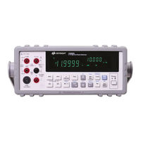
Agilent Technologies U3402A User's Manual And Service Manual (127 pages)
51/2 Digit Dual Display Multimeter
Brand:
Agilent Technologies
| Category:
Multimeter
| Size: 6.29 MB
Table of Contents
Table of Contents
11
Safety Symbols
3
General Safety Information
5
Environmental Conditions
7
In this Guide
10
1 Getting Started Tutorial
19
Checking the Shipping Contents
19
Connecting Power to the Multimeter
19
Stacking the U3402A
19
Adjusting the Handle
19
Introducing the Agilent U3402A Dual Display Multimeter
20
Checking the Shipping Contents
21
Connecting Power to the Multimeter
22
Stacking the U3402A
23
Figure 1-1 Stacking the U3402A
23
Adjusting the Handle
24
Figure 1-2 Type of Handle Position
24
Figure 1-3 Attaching and Detaching the Handle
24
Product at a Glance
25
Product Dimensions
25
Figure 1-4 U3402A Dimensions
25
The Front Panel at a Glance
26
Figure 1-5 Front Panel
26
The Display at a Glance
27
Table 1-1 Display Annunciators
27
Figure 1-6 VFD Full Display with All Segments Illuminated
27
The Keypad at a Glance
29
Table 1-2 Keypad Functions
29
Figure 1-7 Keypad
29
The Terminals at a Glance
32
Figure 1-8 Input Terminal
32
Table 1-3 Input Terminal for Different Measurement Functions
33
The Rear Panel at a Glance
34
Figure 1-9 Rear Panel
34
Making Measurements
35
Performing Voltage Measurements
36
Figure 1-10 ACV Terminal Connection and Display
36
Figure 1-11 DCV Terminal Connection and Display
37
Performing Current Measurements
38
Figure 1-12 ACI RMS or DCI (Ma) Terminal Connection and
38
Figure 1-13 ACI RMS or DCI (A) Terminal Connection and
39
Performing Frequency Measurements
40
Figure 1-14 Frequency Terminal Connection and Display
40
Performing Resistance Measurements
41
Figure 1-15 2-Wire W Terminal Connection and Display
42
Figure 1-16 4-Wire W Terminal Connection and Display
42
Performing Diode/Continuity Test
43
Figure 1-17 Forward-Biased Diode/Continuity Test Terminal Connection and Display
45
Figure 1-18 Reverse-Biased Diode/Continuity Terminal Connection and Display
45
Figure 1-19 2-Wire/Continuity Test Terminal Connection and
47
Selecting a Range
48
Table 1-4 Range Scale Value in Slow, Medium, and Fast Reading
49
Setting the Reading Rate
50
Table 1-5 Reading Rates for Single Function Measurements
50
Figure 1-20 Reading Rate Annunciator
50
2 Operations and Features
51
Combination of Math Operations
51
2 Operations and Features
52
Operating Math Operations
52
Table 2-1 Math Operations for Different Measurement
52
Dbm
53
Figure 2-1 Typical Dbm Operation Display
53
Rel
54
Figure 2-2 Typical Rel Operation Display
54
Minmax
55
Figure 2-3 Typical Max Operation Display
55
Figure 2-4 Typical Min Operation Display
56
Comp
57
Figure 2-5 Typical Comp Operation Display
57
Hold
58
Figure 2-6 Typical Hold Operation Display
58
Combination of Math Operations
59
Table 2-2 Descriptions for Combined Math Operations
60
Figure 2-7 Combined Math Operations Sequence
60
Using the Secondary Display
61
Figure 2-8 Secondary Display
61
Table 2-3 Description for Dual Display Combination
62
Using the Setup Menu
63
Table 2-4 Setup Menu and Communication Parameters
63
Changing the Configurable Settings
64
3 Application Tutorial
65
Application Tutorial
66
Dual Display Operation Examples
67
Measure DC Voltage and AC Ripple on a Rectification Circuit
67
Figure 3-1 Terminal Connection When Measuring DC Voltage and AC Ripple on a Rectification Circuit
67
Measure AC and DC Current on a Rectification Circuit
68
Measure AC Voltage and Frequency on an AC Circuit
69
Measure DC Voltage and DC Current on a Transistor Circuit or Load
70
Measure Resistance Using 2-Wire Mode
72
Measure Resistance Using 4-Wire Mode
73
Measure True RMS AC+DC
74
Applications for Using Dual Display
66
Table 3-1 Typical Combinations and Applications When Using Dual
66
4 Performance Test
75
Calibration Overview
76
Agilent Technologies Calibration Services
76
Calibration Interval
76
Recommended Test Equipment
77
Table 4-1 Recommended Test Equipments
77
Test Considerations
78
DC Voltage Verification Test
79
Performance Verification Test Overview
79
Performance Verification Test
79
Input Terminals
80
Table 4-2 DC Voltage Verification Test
80
DC Current Verification Test
81
Table 4-3 DC Current Verification Test
81
Resistance Verification Test
82
Table 4-4 2-Wire W Verification Test
82
Diode Verification Test
85
Frequency Verification Test
85
Table 4-6 Diode Verification Test
85
Table 4-7 Frequency Verification Test
85
AC Voltage Verification Test
86
Table 4-8 AC Volts Verification Test
86
AC Current Verification Test
87
Table 4-9 AC Current Verification Test
87
5 Disassembly and Repair
89
5 Disassembly and Repair
90
Operating Checklist
90
Types of Service Available
91
Repackaging for Shipment
92
Cleaning
92
To Replace the Power Line Fuse
93
Table 5-1 Type of Supplied Fuse
93
To Replace a Current Input Fuse
94
Electrostatic Discharge (ESD) Precautions
94
Table 5-2 Type of Current Input Fuse
94
Mechanical Disassembly
95
Replaceable Parts
101
To Order Replaceable Parts
101
6 Specifications and Characteristics
103
DC Specifications
104
Table 6-1 DC Resolution, Full Scale Reading, and Accuracy
104
AC Specifications
107
Table 6-2 AC Voltage Resolution, Full Scale Reading, and Accuracy
107
True RMS AC Voltage (AC Coupling Mode)
107
True RMS AC Voltage (AC+DC Coupling Mode)
108
True RMS AC Current (AC Coupling Mode)
109
Frequency
110
Table 6-6 Frequency Resolution and Accuracy
110
True RMS AC Current (AC+DC Coupling Mode)
110
Decibel (Db) Calculation
111
Table 6-7 Range and Accuracy (±Db)
111
Supplemental Measurement Specifications
112
Display Update Rate
112
Measurement Specifications
112
Table 6-8 Full Scale Display Update Rates
112
Table 6-9 Supplemental Measurement Specifications
112
Reading Rates
119
Table 6-10 Reading Rates for Single Display (Readings/Second (Approx))
119
Table 6-11 Reading Rates for the Dual Display (Readings/Second (Approx))
120
General Characteristics
121
Table 6-12 General Characteristics
121
To Calculate Total Measurement Error
123
Accuracy Specifications
124
Transfer Accuracy
124
One-Year Accuracy
124
Temperature Coefficients
124
Configuring for Highest Accuracy Measurements
125
Advertisement
Agilent Technologies U3402A User's And Service Manual (129 pages)
5 1/2 Digit Dual Display Multimeter
Brand:
Agilent Technologies
| Category:
Multimeter
| Size: 6.57 MB
Table of Contents
Safety Symbols
3
Regulatory Markings
4
General Safety Information
5
Environmental Conditions
7
In this Guide
11
Table of Contents
13
Getting Started
21
Introducing the Agilent U3402A Dual Display Multimeter
22
Initial Inspection
23
Standard Purchase Items
23
Original Packaging
24
Connecting Power to the Multimeter
25
Stacking the U3402A
26
Figure 1-1 Stacking the U3402A
26
Adjusting the Handle
27
Figure 1-2 Type of Handle Position
27
Figure 1-3 Attaching and Detaching the Handle
27
Product at a Glance
28
Product Dimensions
28
Figure 1-4 U3402A Dimensions
28
The Front Panel at a Glance
29
Figure 1-5 Front Panel
29
The Display at a Glance
30
Figure 1-6 VFD Full Display with All Segments Illuminated
30
Table 1-1 Display Annunciators
30
The Keypad a a Glance
32
Figure 1-7 Keypad
32
Table 1-2 Keypad Functions
32
The Terminal at a Glance
35
Figure 1-8 Input Terminal
35
Table 1-3 Input Terminal for Different Measurement Functions
36
The Rear Panel at a Glance
37
Figure 1-9 Rear Panel
37
Operations and Features
39
Making Measurements
40
Performing Voltage Measurements
41
Figure 2-1 ACV Terminal Connection and Display
41
Figure 2-2 DCV Terminal Connection and Display
42
Performing Current Measurements
43
Figure 2-3 ACI RMS or DCI (Ma) Terminal Connection and Display
43
Figure 2-4 ACI RMS or DCI (A) Terminal Connection and Display
44
Performing Frequency Measurements
45
Figure 2-5 Frequency Terminal Connection and Display
45
Performing Resistance Measurements
46
Figure 2-6 2-Wire Terminal Connection and Display
46
Performing Diode/Continuity Test
47
Figure 2-7 4-Wire Terminal Connection and Display
47
Figure 2-8 Forward-Biased Diode/Continuity Test Terminal Connection and Display
49
Figure 2-9 Reverse-Biased Diode/Continuity Terminal Connection and Display
49
Figure 2-10 2-Wire/Continuity Test Terminal Connection and Display
51
Selecting a Range
52
Table 2-1 Range Scale Value in Slow, Medium, and Fast Reading Rate
53
Setting the Reading Rate
54
Figure 2-11 Reading Rate Annunciator
54
Table 2-2 Reading Rates for Single Function Measurements
54
Selecting Secondary Display
56
Figure 2-12 Secondary Display
56
Table 2-3 Description for Dual Display Combination
57
Using the Setup Menu
58
Table 2-4 Setup Menu and Communication Parameters
58
Changing the Configurable Settings
59
Selecting Local Operation Mode
60
Operating Math Operations
61
Table 2-5 Math Operations for Different Measurement Functions
61
Dbm
62
Figure 2-13 Typical Dbm Operation Display
62
Rel
63
Figure 2-14 Typical Rel Operation Display
63
Minmax
64
Figure 2-15 Typical Max Operation Display
64
Figure 2-16 Typical Min Operation Display
65
Comp
66
Figure 2-17 Typical Comp Operation Display
66
Hold
67
Figure 2-18 Typical Hold Operation Display
67
Combination of Math Operations
68
Figure 2-19 Combined Math Operations Sequence
69
Table 2-6 Descriptions for Combined Math Operations
69
Measurement Tutorial
71
Applications for Using Dual Display
72
Table 3-1 Typical Combinations and Applications When Using Dual Display
72
Dual Display Operation Examples
73
Measure DC Voltage and AC Ripple on a Rectification Circuit
73
Figure 3-1 Terminal Connection When Measuring DC Voltage and AC Ripple on a Rectification Circuit
73
Measure AC and DC Current on a Rectification Circuit
74
Figure 3-2 Terminal Connection When Measuring AC and DC Current on a Rectification Circuit
74
Measure AC Voltage and Frequency on an AC Circuit
75
Measure DC Voltage and DC Current on a Transistor Circuit or Load
76
Measure Resistance Using 2-Wire Mode
78
Measure Resistance Using 4-Wire Mode
79
Measure True RMS AC+DC
80
Performance Test
81
Calibration Overview
82
Agilent Technologies Calibration Services
82
Calibration Interval
82
Recommended Test Equipment
83
Table 4-1 Recommended Test Equipments
83
Test Considerations
84
Input Connections
84
Performance Verification Test Overview
85
Performance Verification Test
85
DC Voltage Verification Test
85
Table 4-2 DC Voltage Verification Test
86
DC Current Verification Test
87
Table 4-3 DC Current Verification Test
87
Resistance Verification Test
88
Table 4-4 2-Wire Verification Test
88
Diode Verification Test
91
Frequency Verification Test
91
Table 4-6 Diode Verification Test
91
Table 4-7 Frequency Verification Test
91
AC Voltage Verification Test
92
Table 4-8 AC Volts Verification Test
92
AC Current Verification Test
93
Table 4-9 AC Current Verification Test
93
Disassembly and Repair
95
Operating Checklist
96
Types of Service Available
97
Cleaning
98
Repackaging for Shipment
98
To Replace the Power Line Fuse
99
Table 5-1 Type of Supplied Fuse (According to Country of Destination)
99
To Replace a Current Input Fuse
100
Electrostatic Discharge (ESD) Precautions
100
Mechanical Disassembly
101
Replaceable Parts
107
Table 5-2 Replaceable Parts
107
Rack Mounting
108
Specifications and Characteristics
109
General Characteristics
110
Measurement Category
112
Measurement Category Definitions
112
Specifications
113
DC Voltage
113
Table 6-1 DCV Resolution, Full Scale Reading, and Accuracy
113
DC Current
114
Table 6-2 DCI Resolution, Full Scale Reading, and Accuracy [±(% of Reading + Count)]
114
AC Voltage (True RMS, AC Coupling Mode)
115
Table 6-3 ACV Resolution, Full Scale Reading, and Accuracy [±(% of Reading + Count)]
115
AC Voltage (True RMS, AC+DC Coupling Mode)
116
Table 6-4 Acvac+DC Resolution, Full Scale Reading, and Accuracy [± (% of Reading + Count)]
116
AC Current (True RMS, AC Coupling Mode)
117
Table 6-5 ACI Resolution, Full Scale Reading, Burden Voltage, and Accuracy [± (% of Reading + Count)]
117
AC Current (True RMS, AC+DC Coupling Mode)
118
Table 6-6 Aciac+DC Resolution, Full Scale Reading, Burden Voltage, and Accuracy [± (% of Reading + Count)]
118
Resistance
119
Diode Test/Continuity
120
Resistance/Continuity (2-Wire)
120
Frequency
120
Decibel (Db) Calculation
121
Supplemental Specifications
122
Display Counts
122
Measurement Specifications
122
To Calculate Total Measurement Error
127
Accuracy Specifications
128
Transfer Accuracy
128
Agilent Technologies U3402A Quick Start Manual (61 pages)
5 1/2 Digit Dual Display Multimeter
Brand:
Agilent Technologies
| Category:
Multimeter
| Size: 4.01 MB
Table of Contents
English
3
Table of Contents
3
The Front Panel at a Glance
5
The Display at a Glance
6
Getting Started
8
Connect the Power Cord
8
Adjust the Carrying Handle
8
Connect the Test Leads to the Input Terminals
9
Turn on the Multimeter
9
Select a Function
10
Set the Range
10
Set the Reading Rate
10
Using the Secondary Display
11
Math Operation
11
For more Information
12
Français
15
La Face Avant
17
L'écran D'un Coup D'œil
18
Mise en Route
20
Branchez Le Cordon D'alimentation
20
Réglage de la Poignée de Transport
20
Raccordement des Cordons de Test Aux Bornes D'entrée
21
Mise Sous Tension du Multimètre
21
Sélection D'une Fonction
22
Définition de la Plage
22
Définition de la Vitesse de Lecture
22
Utilisation de L'affichage Secondaire
23
Opération Mathématique
23
Pour de Plus Amples Informations
24
Deutsch
27
Das Vordere Bedienfeld auf einen Blick
29
Die Anzeige auf einen Blick
30
Erste Schritte
32
Anschließen des Netzkabels
32
Anpassen des Tragegriffs
32
Anschließen der Testleitungen an die Eingangsanschlüsse
33
Einschalten des Multimeters
33
Auswählen einer Funktion
34
Einstellen des Bereichs
34
Einstellen der Leserate
34
Verwenden der Sekundäranzeige
35
Math. Operation
35
Weitere Informationen
36
漢語
39
端 面 板 一 瞥
41
顯 示 器 一 瞥
42
入 門
44
調 節 手 提 握 柄
44
連 接 電 源 線
44
將 測 試 引 線 連 接 至 輸 入 端 子
45
開 啟 萬 用 電 表
45
設 定 範 圍
46
設 定 讀 取 速 率
46
選 取 功 能
46
使 用 次 要 顯 示 器
47
數 學 運 算
47
有 關 詳 細 資 訊
48
日本語
51
ロ ン ト ・ パ ネ ル の 概 要
53
デ ィ ス プ レ イ の 概 要
54
使 用 前 の 準 備
56
持 ち 運 び 用 ハ ン ド ル を 調 整 し ま す
56
電 源 コ ー ド を 接 続 し ま す
56
テ ス ト ・ リ ー ド を 入 力 端 子 に 接 続 し ま す
57
マ ル チ メ ー タ を オ ン に し ま す
57
レ ン ジ を 設 定 し ま す
58
機 能 を 選 択 し ま す
58
測 定 速 度 を 設 定 し ま す
58
セ カ ン ダ リ ・ デ ィ ス プ レ イ の 使 用
59
演 算 機 能
59
詳 細
60
Advertisement
Advertisement
Related Products
Agilent Technologies U3401A
Agilent Technologies U3606B
Agilent Technologies U3606A
Agilent Technologies U2741A
Agilent Technologies U1252B
Agilent Technologies U1242A
Agilent Technologies U1253B
Agilent Technologies U1231A
Agilent Technologies U1242B
Agilent Technologies U1241B
Agilent Technologies Categories
Measuring Instruments
Laboratory Equipment
Test Equipment
Water Pump
Power Supply
More Agilent Technologies Manuals
Login
Sign In
OR
Sign in with Facebook
Sign in with Google
Upload manual
Upload from disk
Upload from URL