
User Manuals: AERMEC PCO5 Control Panel
Manuals and User Guides for AERMEC PCO5 Control Panel. We have 7 AERMEC PCO5 Control Panel manuals available for free PDF download: User Manual

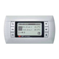
AERMEC PCO5 User Manual (46 pages)
Screw w/w range
Brand: AERMEC
|
Category: Control Panel
|
Size: 7 MB
Table of Contents
Advertisement
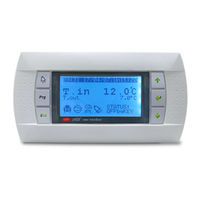
AERMEC PCO5 User Manual (36 pages)
For NRG-Small
Brand: AERMEC
|
Category: Control Panel
|
Size: 4 MB
Table of Contents
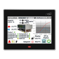
AERMEC PCO5 User Manual (32 pages)
Range a/w scroll
Brand: AERMEC
|
Category: Control Panel
|
Size: 5 MB
Table of Contents
Advertisement
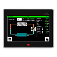
AERMEC PCO5 User Manual (28 pages)
NRB-Large
Brand: AERMEC
|
Category: Recording Equipment
|
Size: 7 MB
Table of Contents
AERMEC PCO5 User Manual (28 pages)
Brand: AERMEC
|
Category: Control Panel
|
Size: 5 MB
Table of Contents
AERMEC PCO5 User Manual (20 pages)
Brand: AERMEC
|
Category: Control Panel
|
Size: 4 MB
Table of Contents

AERMEC PCO5 User Manual (24 pages)
Multipurpose
Brand: AERMEC
|
Category: Recording Equipment
|
Size: 4 MB
Table of Contents
Advertisement