
Related Manuals for AERMEC PCO5


Summary of Contents for AERMEC PCO5
- Page 1 T r a n s l a t i o n o f O r i g i n a l i n s t r u c t i o n s NRG-Small User manual CARD PCO5 - PANEL PGD1 w w w . a e r m e c . c o m...
- Page 2 All specifications are subject to change without prior notice. Although every effort has been made to ensure accuracy, Aermec shall not be held liable for any errors or...
-
Page 3: Table Of Contents
TABLE OF CONTENTS Digital Inputs (pCOE - glycolfree models) ........p. 17 1. User interface (PGD1) ...............p. 6 Digital outputs (pCOE - glycolfree models) ....... p. 17 Start-up procedure ................p. 6 Analogue Inputs (pCOE models with total recovery)..... p. 17 Function of the PGD1 control panel keys ........p. 6 Digital Inputs (pCOE models with total recovery) .... - Page 4 Setting the public holidays on the calendar ......p. 24 Configuration of the units of measure ........p. 32 Configures the installer menu password ........p. 32 8. Installer menu ................... p. 25 9. List of alarms Password to access the installer menu (0000) ......p. 25 ..................
-
Page 5: User Interface (Pgd1)
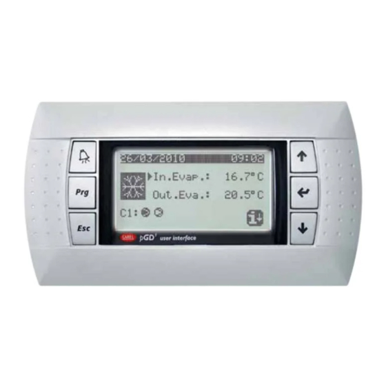
USER INTERFACE (PGD1) 1.2 FUNCTION OF THE PGD1 CONTROL PANEL KEYS Function of the PGD1 control panel keys: : Displays the list of active alarms and the alarm log : Pressing this key activates navigation between the menus (orange LED on = winter operating mode active);... - Page 6 Menu icons: IN/OUT: This menu contains advanced information about operating the unit; ON/OFF: This menu is used to activate or deactivate the unit; it also provides state information; System: This menu is used to set the operating mode, the setpoints for water production and the time bands to be applied to the system;...
-
Page 7: Main Menu
This mask is used to display the unit's general status: This mask is used to display the cooling circuit's general status; if the unit has mul- tiple circuits, each will have a dedicated window: Aermec Fri 08:35 Circuit 1 9.5°C 18.9bar... -
Page 8: Master Unit Monitor
2.5 MASTER UNIT MONITOR 2.7 GLYCOL FREE MONITOR NB: this mask is only available on the Master unit, if the system has a WARNING: this mask is available on glycolfree units. Master/Slave configuration with multiple units. This mask is used to display the status of the glycolfree circuit: This mask is used to display the data related to the system's total power demand Glycol Free and the relative power percentages divided among the units connected to the sys-... -
Page 9: Total Recovery Monitor
2.9 TOTAL RECOVERY MONITOR WARNING: this mask is available on units with total recovery. This mask is used to display the status of the total recovery: Total Recovery Inlet water: 15.1°C Out Total Rec.: 15.1°C O unit Total require: — Display of the water temperature value of the total recovery input probe; —... -
Page 10: Input/Output Menu
INPUT/OUTPUT MENU 3.3 DEFROSTING MONITOR This window contains the information concerning the status of defrosting on the unit:if the unit has multiple circuits, each will have a dedicated window: 3.1 FAN MONITOR Defrost This window summarises the status of the fans and the utilised setpoints:if the unit has multiple circuits, each will have a dedicated window: Disabled High ext. -
Page 11: Multifunction Input Monitor
Plant Input Multifunction (ID18): ACTIVE Variable SetPoint pCO5 U10= 45.0°C Digital Input ID18: this value indicates the state of the digital input connected to multifunction input (U10) enabling, whose states can be: — OPEN: multifunction input (U10) NOT ENABLED; — CLOSED: multifunction input (U10) ENABLED;... -
Page 12: Analogue Inputs (Pec)
3.6 ANALOGUE INPUTS Analogue input Code Description Note evaporator water inlet probe evaporator water outlet probe Cold Single circuit/Dual circuit External air sensor Free cooling/Glycolfree Single circuit/Dual circuit Recovery Single circuit/Dual circuit Fan Series Fan Alarm Contacts Series Heat pump Single circuit/Dual circuit Cold Single circuit/Dual circuit SGP1A Compressor 1 Circuit 1 discharge gas probe... - Page 13 3.7 DIGITAL INPUTS Digital Input Code Description Note Flow switch Circuit 1 high pressure pressure switch / Circ.1 discharge gas thermostat QMF1 Thermomagnetic fan switch Phase monitor QM11 Compressor 1 circuit 1 thermomagnetic switch Cooling only Single circuit/Dual circuit Free cooling/Glycolfree Dual circuit QM21 Compressor 2 circuit 1 thermomagnetic switch Recovery Single circuit/Dual circuit...
- Page 14 3.8 DIGITAL OUTPUTS DIGITAL outputs Code Description Note MPE1 Pump 1 evaporator Cooling only Single circuit/Dual circuit CP1A Compressor 1 Circuit 1 Free cooling/Glycolfree Single circuit/Dual circuit Recovery Single circuit/Dual circuit Heat pump Single circuit/Dual circuit Cooling only Single circuit/Dual circuit CP1B Compressor 2 Circuit 1 Free cooling/Glycolfree Dual circuit...
-
Page 15: Digital Output (Pec)
3.9 ANALOGUE OUTPUTS ANALOGUE outputs Code Description Note FAN1 Modulating fans unit 1 FAN2 Modulating fans unit 2 NRG Large FAN3 Modulating fans unit 3 NRG Large Cold Single circuit Free cooling/Glycolfree Single circuit Tray heater Recovery Single circuit Heat pump single circuit 3.10 ANALOGUE INPUTS (PEC) Analogue Input (PEC) Code... -
Page 16: Analogue Inputs (Evd)
3.12 ANALOGUE INPUTS (EVD) Analogue Inputs (EVD) Code Description Note Cold single circuit/dual circuit TBP1 Circuit 1 Low pressure transducer Free cooling/Glycolfree Single circuit/Dual circuit Recovery Single circuit/Dual circuit Cold single circuit/dual circuit SGA1 Circ. 1 intake temperature probe Free cooling/Glycolfree Single circuit/Dual circuit Recovery Single circuit/Dual circuit Cold dual circuit TBP2... -
Page 17: Digital Inputs (Pcoe Models With Total Recovery)
3.19 DIGITAL INPUTS (PCOE MODELS WITH TOTAL RECOVERY) Digital inputs (pCOE) Code Description Note Recovery flow switch Recovery external pump thermal switch The possible status for each digital input or output can be: — CLOSED: load active; — OPEN: load not active; 3.20 DIGITAL OUTPUTS (PCOE MODELS WITH TOTAL RECOVERY) Digital inputs (pCOE) Code... -
Page 18: Digital Inputs (Pcoe - Variable Flow Rate / Supplementary Heater)
3.24 DIGITAL INPUTS (PCOE - VARIABLE FLOW RATE / SUPPLEMENTARY HEATER); Digital inputs Code Description Note VPF3V 3 Way Valve Only for Variable Flow Rate The possible status for each digital input or output can be: — CLOSED: load active; —... -
Page 19: On/Off Menu
ON/OFF MENU 4.1 GENERAL ON/OFF This window makes it possible to view the general state of the system as well as to turn the unit on or off: On/O Unit Plant O General General enable: Display of the general system state: —... -
Page 20: System Menu
SYSTEM MENU 5.1 SELECTING THE SYSTEM OPERATING MODE 5.3 SETTING THE VALUES FOR THE SECONDARY SETPOINTS This mask is used to display the current unit state, to turn the unit on or off and to select the operating mode: This mask is used to set the values to assign to the secondary working setpoints: Plant Plant O General... -
Page 21: Set The Time Bands (C) And (D)
5.5 SET THE TIME BANDS (C) AND (D) 5.8 SETTING THE SEASON CHANGE FROM THE CALENDAR (COOLING) NB: this mask is only visible if "BY CLOCK" is selected on the page "Se- lecting the system operating mode"; NB: this mask is only visible if "BY CALENDAR" is selected on the page This mask is used to set the times and action to assign to the time bands (c) and (d): "Selecting the system operating mode";... -
Page 22: Recovery Menu
RECOVERY MENU 6.1 ENABLING RECOVERY WARNING: this mask is available on units with total recovery. This mask is used to display the actual status of the total recovery, and to enable or disable the total recovery: O General Switch On: The mask displays the total recovery status;the available options are: —... -
Page 23: Clock Menu
CLOCK MENU 7.1 SETTING SYSTEM DATE AND TIME This mask is used to set the system date and time: Clock Day: MONDAY Time: 16 MARZ 2020 Hour: 16:29 7.2 SETTING THE AUTOMATIC SUMMER/WINTER TIME CHANGE This mask is used to set the automatic change between summer and winter time, it is also possible to define the day the change is made: Clock Automatic change... -
Page 24: Installer Menu
INSTALLER MENU 8.1 PASSWORD TO ACCESS THE INSTALLER MENU (0000) 8.3 ENABLE CHANGE OVER AND ON/OFF BY SUPERVISOR This mask is used to enter the password necessary for accessing the installer menu This mask is used to enable or disable the change over (season change) and unit (the password is 0000): on/off via BMS: Insert password... -
Page 25: Enables System On/Off From Digital Input (Id17)
8.5 ENABLES SYSTEM ON/OFF FROM DIGITAL INPUT Installer (ID17) Cooling regulation This mask is used to enable unit on/off via the digital input (ID17): COMPENS.TEMP. Input enable ID17: ON/OFF plant Di erential: 8.0°C The type of setpoint indicates which logic is used for managing the working set- point;... -
Page 26: Climatic Curve Configuration In Heating Mode
8.10 CLIMATIC CURVE CONFIGURATION IN HEATING MODE Differential: this value indicates the differential to apply to the anti-freeze activation threshold; when the water temperature (inlet or outlet) is higher than the threshold value plus the differential, the anti-freeze alarm is deactivated; This window is used to set the temperatures (minimum and maximum) and the Pump ON power: by changing this value, it is possible to decide whether to auto- maximum differential that will be applied to the working setpoint in heating mode... -
Page 27: Configure Fans At Low Temperatures
Installer Installer Total recovery Multifunction Input Antifreeze alarm Con g. Input (U10): Threshold: 3.0°C NOT PRESENT Di erential: 1.0°C Type: 4-20mA Min: 4.0mA Max: 20.0mA Threshold: the anti-freeze alarm is generated below the temperature of the recov- U10: this value indicates which function to assign to the multifunction input U10; ery input or recovery output probes;... -
Page 28: Configuration Of Variable Setpoint For Input (U10)
Minimum temp.: this value indicates the minimum temperature (NTC signal) to as- Installer sign to the minimum value for the function set on the multifunction input (power limitation or variable setpoint); Suppl.electric heaters Maximum temp: this value indicates the maximum temperature (NTC signal) to as- sign to the maximum value for the function set on the multifunction input (power Number: limitation or variable setpoint);... -
Page 29: Compressor Start-Up Monitor
8.29 CONFIGURE MASTER SLAVE Hour meter This window is used to configure the parameters for unit Master/Slave manage- Circuit 1 ment: Installer Compressor 1: 0000h Master/Slave Compressor 2: 0000h Compressor 3: 0000h Unit: ALONE Step: 1.0% Slave Pump o with Compressor o : 8.27 COMPRESSOR START-UP MONITOR This window displays the data relative to the compressor start-ups on the unit:... -
Page 30: Free Cooling Configuration (Yield Control)
8.31 FREE COOLING CONFIGURATION (YIELD CONTROL) Setpoint: indicates the pressure value that the regulation tries to maintain at the ends of the evaporator, by opening and closing the bypass valve; Diff.: differential used when regulating the bypass valve; WARNING: this mask is available on free cooling units. Integral: integral time used when regulating the bypass valve;... -
Page 31: Unit Information Monitor
This window is used to change the “Installer” menu access parameter: Password 8.37 UNIT INFORMATION MONITOR This window contains information concerning the unit code, the software version and the machine test date: Information Aermec S.p.A. New password Installer: 0000 NRG0654°H°°°°°00 Code: Ver.:... - Page 32 LIST OF ALARMS There are three types of alarm resets: — Auto: automatic, when the event causing the alarm stops, also the alarm disappears. — Manual: manual, to restart normal operation manual acknowledgement is necessary. — Semi-auto: semi-automatic, the alarm is automatic but if it is present more than “n” times, it then becomes manual. The interventions are decreased by one unit every hour. Furthermore, there is a “timeout”, after which the alarm becomes manual, even if the maximum number of interventions is reached.
- Page 33 Table of contents Meaning Reset AL98 PCOE DK expansion offline alarm (address=3) Manual AL99 Evaporator common outlet faulty probe alarm Manual AL100 Evaporator 2 output faulty probe alarm Manual AL102 Water inlet temp. out of operating limits Manual AL103 Suction probe broken or not connected circ. 1 Manual AL104 Suction probe broken or not connected circ.
- Page 34 Hardware - alarm set 1 Meaning Reset T4 sensor Manual T5 sensor Manual T6 sensor Manual T7 sensor P3 sensor Manual P4 sensor Manual T8 sensor T9 sensor Manual T10 sensor Manual T11 sensor Manual T12 sensor Manual Software - alarm set 2 Software - alarm set 2 Meaning Reset...
- Page 36 SCARICA L’ULTIMA VERSIONE: DOWNLOAD THE LATEST VERSION: TÉLÉCHARGER LA DERNIÈRE VERSION: http://www.aermec.com/qrcode.asp?q=17285 http://www.aermec.com/qrcode.asp?q=17286 http://www.aermec.com/qrcode.asp?q=17287 A E R M E C S . p . A . V i a R o m a , 9 9 6 - 3 7 0 4 0 B e v i l a c q u a ( V R ) - I t a l y P h o n e + 3 9 0 4 4 2 6 3 3 1 1 1 - F a x + 3 9 0 4 4 2 9 3 5 7 7 s a l e s @ a e r m e c .
Need help?
Do you have a question about the PCO5 and is the answer not in the manual?
Questions and answers