
Related Manuals for AERMEC PCO5


Summary of Contents for AERMEC PCO5
- Page 1 T r a n s l a t i o n o f O r i g i n a l i n s t r u c t i o n s Screw w/w range User manual CARD PCO5 - TOUCH PANEL PGDX - PANEL PGD1 w w w . a e r m e c . c o m...
- Page 3 All specifications are subject to change without prior notice. Although every effort has been made to ensure accuracy, Aermec shall not be held liable for any errors or...
-
Page 4: Table Of Contents
TABLE OF CONTENTS Language selection menu ............... p. 16 1. User interface (pGDx) ...............p. 6 Installer menu ..................p. 17 Menu structure..................p. 6 10. Alarm Menu icons ....................p. 6 ...................... p. 20 Signal only alarms ................p. 20 2. Home menu ...................p. 7 Circuit alarms ..................p. 20 Home menu icons ..................p. 8 Serious alarms .................. - Page 5 Compressed status monitor (C) ............. p. 29 Input current monitor................ p. 36 Gas status monitor (A) ............... p. 30 Cooling setpoint monitor ..............p. 36 Gas status monitor (B) ............... p. 30 Heating setpoint monitor ..............p. 36 Valve 1 and valve 2 status monitor ..........p. 30 Multifunction input with cooling capacity limit monitor ..
-
Page 6: User Interface (Pgdx)
USER INTERFACE (PGDX) 1.1 MENU STRUCTURE All the functions for managing the unit as well as the information about its opera- The user has the pGDx panel available with a 4.3" touch screen, which is used to tion are displayed on the unit control panel; all the functions and information are display the complete machine status and change the parameters to configure it. -
Page 7: Home Menu
This mask displays: 1. General unit status: — Current date and time — Machine model; — Control card whose parameters are displayed (pCO5+) — Condenser inlet temperature (CN); — Condenser outlet temperature (CN); — High, low pressure and compressor status;... -
Page 8: Home Menu Icons
2.1 HOME MENU ICONS The icons identify the main machine users such as compressors, electronic valves, pumps and communicate their status: Icon Description Note There are different types of pump icons: White: pump stopped Pump Red: pump alarm Green: pump operating There are different types of valve icons: White: electronic valve stopped Valve... -
Page 9: Chiller Menu
CHILLER MENU The Chiller menu makes it possible to identify the machine status and change the ON/OFF 10:04:11 general enabling. ON/OFF 10:04:11 Actual Setpoint 0.0 °C O by Keyboard Actual Setpoint 7.0 °C These masks are used to: — Select the operating mode —... -
Page 10: Unit Selection Menu
UNIT SELECTION MENU The pGDx panel manages up to 3 cards: The Unit Selection menu makes it possible to select the compressor unit with which Card 1 (Master): Controls compressor 1 to dialogue. Each compressor is controlled by a single separate control card. As a result, bi-com- pressor and tri-compressor machines have 2 or 3 control cards, each with its sizes and parameters. -
Page 11: Alarm Menu
ALARM MENU It is possible to consult the list of active alarms in this section. Each line represents a single alarm that occurred in the unit at the selected moment. Some alarms are only present on the master card (address 1), whereas others can ALARMS 03/12/21 10:08:57... -
Page 12: Clock Menu
CLOCK MENU This menu is used to view and modify the following parameters: — Time — Date — Day of the week — Programmer timer and time bands for every day of the week 6.1 TIME, DATE AND DAY DISPLAY MONITOR TIMEZONE 10:21:07 Display Date Time... -
Page 13: Input/Output Menu
INPUT/OUTPUT MENU — B4: discharge gas temperature probe reading This menu is used to display the state of the inputs and outputs, both digital as well — B5: evaporator water outlet temperature probe reading as analogue. — B6: Ammetric transformer inlet (A) The first mask, which is present only in the master card parameters, summarises the —... -
Page 14: Flammable Gas And Software Version Monitor
7.6 FLAMMABLE GAS AND SOFTWARE VERSION MONITOR — Suction Low, Discharge High — Discharge High — Suction High, Discharge High 10:25:36 — Suction High pCO5+ Software — Suction High, Discharge Low 0.0.19 23/11/21 Release Date Version — Discharge Low 3. Compressor status summary:... -
Page 15: Diagram Menu
DIAGRAM MENU In this menu it is possible to consult the live updated diagrams of some sizes, which are relevant for machine operation. 8.1 WATER INLET AND OUTLET TEMPERATURE MONITOR WATER IN/OUT 03/12/21 10:29:20 13.5 10.1 10:24:13 10:26:43 10:29:13 10:31:43 10:34:13 [°C] Outlet Temperature... -
Page 16: Settings Menu
SETTINGS MENU This menu is used to enter the submenus that contain the machine configuration parameters. SETTINGS 02/12/21 14:57:28 Service Installer Manufacturer The parameters are organised in the following categories: Language selection: Pressing this key displays the system language selection page, using the flag of the selected language. Installer menu (password required): Pressing this key makes it possible to access the first level parameters, those that the machine installed can change for system requirements. -
Page 17: Installer Menu
9.2 INSTALLER MENU This menu contains the parameters necessary for the machine configuration and its functions. Password monitor to access the installer menu Digital input and supervisor command enabling monitor Enter the password to access the menu (the password is 0000). INSTALLER 10:38:37 SETTINGS... - Page 18 Multifunction input monitor INSTALLER 10:41:52 INSTALLER 10:43:40 Regulation Regulation Outlet Common Temperature Probe Probe 7 Multifunction Con guration Integration Regulation Type Time Function None Type Regulation °C Temperature Temperature Band 20.0 °C 35.0 °C High Electronic Valve R1234ze Refrigerant Gas Number Glycolated Water Glycolated Water...
- Page 19 Heating and cooling setpoint monitor Multifunction input enabled with setpoint compensation with temperature probe function: INSTALLER 10:45:44 — Cooling setpoint compensation corresponding to the minimum size of the in- Probe 7 Multifunction Con guration — Cooling setpoint compensation corresponding to the maximum size of the in- 4-20mA Setpoint Function...
-
Page 20: Alarm
10 ALARM The alarms are divided into the following categories: 1. Signal only alarms (only a signal on the display, alarm relay) 2. Circuit alarms (they deactivate only the relative circuit, signal on the display, alarm relay) 3. Serious alarms (they deactivate all the system circuits, signal on the display, alarm relay) 4. -
Page 21: Alarm Reset
10.5 ALARM RESET Pressing the reset key activates the request to reset the active alarms. ALARMS 03/12/21 10:14:42 Warning Time AL121 03/12/2021 09:57:24 AL069 03/12/2021 09:46:51 Careless resetting of alarms causes severe damage to the unit AL071 03/12/2021 09:46:51 AL091 03/12/2021 09:47:28 Reset Reset... -
Page 22: List Of Alarms
T Memory Excessive Writings · an excessive number of entries in EEPROM detected AL066 T Memory Error · error in the EEPROM memory of card pCO5+ · leak detector contact AL067 Gas Leakage · in machines “G” reset with password is required AL068 Leak detector –... - Page 23 This occurs only at the Warning level AL119 Inverter – envelope error The compressor is working out of envelope AL120 Inverter – serial control timeout · power request from card pCO5+ to inverter timeout AL121 Inverter – communication error AL122 Inverter – datalog error AL123...
-
Page 24: User Interface (Pgd1)
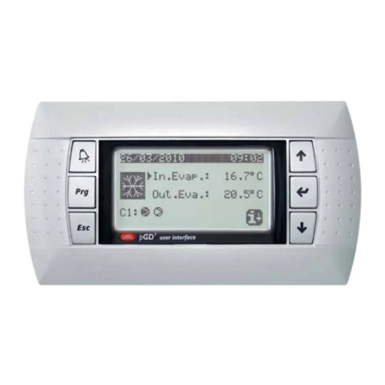
11 USER INTERFACE (PGD1) This window makes it possible to select the language with which the system is started. 11.2 FUNCTION OF THE PGD1 CONTROL PANEL KEYS Function of the PGD1 control panel keys: : Displays the list of active and historical alarms (red LED on = active alarm); : Pressing this key activates navigation between the menus;... -
Page 25: Menu Structure
11.3 MENU STRUCTURE Menu icons: All the functions for managing the unit as well as the information about its opera- tion are displayed on the unit control panel; all the functions and information are IN/OUT: This menu contains advanced information about operating the unit; organised into windows, which are in turn grouped in to menus. -
Page 26: User Operating Procedures
11.4 USER OPERATING PROCEDURES Selecting and modifying a menu To check or modify the operating parameters of the unit it is necessary to use the interface of the control panel on the unit. Once in the menu selected, by following the procedure, it is possible to move be- The basic operations that the user must be capable of, for the correct use of the tween the screens using the arrow keys: the key to move to the previous pa-... -
Page 27: Main Menu
12 MAIN MENU 13 ALARM LOG MENU 30/11/21 10:16 To display the alarm log menu, press the button The menu shows the last 25 alarms that occurred together with some parameters 12.0 °C 35.0 °C stored at the moment the alarm occurred. Alarms history #00006 AL121... -
Page 28: Input/Output Menu
14 INPUT/OUTPUT MENU This menu is used to display the state of the inputs and outputs, both digital as well 14.3 TIA, TUAC AND TGP PROBE VALUES MONITOR as analogue. Analog inputs The first mask, which is present only in the master card parameters, summarises the machine status with a graphic indication of the compressor power (no. -
Page 29: Condenser Water Inlet/Outlet Temperature Monitor
Voltage value at analogue output Y0 and Y1. 14.9 SOFTWARE STATUS MONITOR — Intake temperature read by the compressor — Delivery temperature read by the compressor Aermec WFN — Oil temperature read by the compressor — Minimum operating time remaining — Minimum switching off time remaining Software Version: 0.0.15... -
Page 30: Gas Status Monitor (A)
15 ON/OFF MENU 14.13 GAS STATUS MONITOR (A) The On/Off menu makes it possible to identify the machine status and change the Leak Detector general enabling. Plant Main On/O Gas Level OFF BY KEYB. General Enable: Concentration of flammable gas detected by sensor 1. 14.14 GAS STATUS MONITOR (B) This mask is used to view the machine operating status:... -
Page 31: Chiller Menu
16 CHILLER MENU The Chiller menu makes it possible to identify the machine status and change the 16.4 CURRENT SETPOINT MONITOR general enabling. Current setpoint 10.0 °C 16.1 OPERATING MODE MONITOR Working mode Cooling 100 % Limit Ext. Demand 000 % Current setpoint 7.0 °C —... -
Page 32: Multifunction Input Monitor (C)
16.7 MULTIFUNCTION INPUT MONITOR (C) 17.2 TIMER ENABLING MONITOR Multifunction Enable weekly time zones 000.0 °C Input Power Request 000 % — Multifunction input enabled for cooling capacity request This mask is used to enable the weekly time band timer (Y = enabled, N = disabled). —... -
Page 33: Installer Menu
18 INSTALLER MENU This menu contains the parameters necessary for the machine configuration and 18.4 HIGH PRESSURE TRANSDUCER LIMITS MONITOR its functions. High pressure probe 18.1 PASSWORD MONITOR TO ACCESS THE INSTALLER MENU con guration 4-20mA Enter the password to access the menu (the password is 0000). 00.0bar Installer Password 20mA... -
Page 34: Supervisor Functionality Enabling Monitor
18.11 ADJUSTING TEMPERATURE MONITOR — Supervisor ON/OFF command enabling — Supervisor cooling/heating command enabling Regulat. 18.8 SUPERVISOR FUNCTIONALITY ENABLING MONITOR temperature Demand by Supervisor Type OUTLET Reg.probe Master Demand Limit by Supervisor Adjusting temperature selection (MASTER ONLY): — INLET: Water inlet —... -
Page 35: Type Of Gas Monitor
18.14 TYPE OF GAS MONITOR 18.17 BMS PARAMETERS MONITOR supervisor (BMS) Gas Type R1234ze Address Baudrate 19200 Protocol Modbus Type of refrigerant gas. — Serial address 1 for supervisor — Speed of communication — Type of protocol used for communication with the supervisor: Lon, pCOweb, 18.15 ELECTRONIC VALVE NUMBER MONITOR Modbus... -
Page 36: Ntc Probe Temperature Monitor
18.20 NTC PROBE TEMPERATURE MONITOR 18.23 COOLING SETPOINT MONITOR Probe 7 con g. Probe 7 con g. NTC Type External Setpoint Temp. Low 20.0 °C Cool Set Low 07.0 °C Temp. High 35.0 °C Cool Set High 12.0 °C — NTC type multifunction input enabled (MASTER ONLY) —... -
Page 37: Multifunction Input With External Power Request Monitor
18.26 MULTIFUNCTION INPUT WITH EXTERNAL POWER 18.29 DIGITAL CONTACT ENABLING MONITOR REQUEST MONITOR Enable Digital Probe 7 con g. Demand External Demand Demand Low Demand High 100 % Power request enabling from digital contacts ID 16, ID 17, ID 18 (MASTER ONLY). —... -
Page 38: Language Selection Monitor
18.32 LANGUAGE SELECTION MONITOR Language Language: ENGLISH Push ENTER for change This mask is used to select the language: ENGLISH, ITALIANO, DEUTSCHE, ESPANOL, FRANCAISE. 18.33 NEW PASSWORD FOR GAS ALARM RESET MONITOR Insert another reset alarm password Entering a new password for gas alarm reset. 18.34 NEW PASSWORD FOR INSTALLER MENU MONITOR Insert another... -
Page 39: Alarm
19 ALARM The alarms are divided into the following categories: 1. Signal only alarms (only a signal on the display, alarm relay) 2. Circuit alarms (they deactivate only the relative circuit, signal on the display, alarm relay) 3. Serious alarms (they deactivate all the system circuits, signal on the display, alarm relay) 4. -
Page 40: Alarm Reset
19.5 ALARM RESET To reset the alarms, simply press the key Alarms Warning! Only reset once. If fault re-occurs call assistance! The list of active alarms can be accessed using the arrows 19.6 GAS ALARM RESET In the machines that use flammable gas, there are some alarms that require a password to be reset. This safety measure guarantees that the machine will be put back into operation only after the risk conditions have been eliminated by expert and prepared personnel. -
Page 41: List Of Alarms
T Memory Excessive Writings · an excessive number of entries in EEPROM detected AL066 T Memory Error · error in the EEPROM memory of card pCO5+ · leak detector contact AL067 Gas Leakage · in machines “G” reset with password is required AL068 Leak detector –... - Page 42 This occurs only at the Warning level AL119 Inverter – envelope error The compressor is working out of envelope AL120 Inverter – serial control timeout · power request from card pCO5+ to inverter timeout AL121 Inverter – communication error AL122 Inverter – datalog error AL123 Inverter –...
- Page 46 SCARICA L’ULTIMA VERSIONE: DOWNLOAD THE LATEST VERSION: TÉLÉCHARGER LA DERNIÈRE VERSION: http://www.aermec.com/qrcode.asp?q=18141 http://www.aermec.com/qrcode.asp?q=18142 http://www.aermec.com/qrcode.asp?q=18144 A E R M E C S . p . A . V i a R o m a , 9 9 6 - 3 7 0 4 0 B e v i l a c q u a ( V R ) - I t a l y P h o n e + 3 9 0 4 4 2 6 3 3 1 1 1 - F a x + 3 9 0 4 4 2 9 3 5 7 7 s a l e s @ a e r m e c .
Need help?
Do you have a question about the PCO5 and is the answer not in the manual?
Questions and answers