
Related Manuals for AERMEC PCO5


Summary of Contents for AERMEC PCO5
- Page 1 T r a n s l a t i o n o f O r i g i n a l i n s t r u c t i o n s Multipurpose User manual CARD PCO5 - PANEL PGD1 w w w . a e r m e c . c o m...
- Page 3 All specifications are subject to change without prior notice. Although every effort has been made to ensure accuracy, Aermec shall not be held liable for any errors or...
-
Page 4: Table Of Contents
TABLE OF CONTENTS (4 pipes) ....................p. 15 1. User interface (PGD1) ...............p. 5 7. System menu (2 pipes) Start-up procedure ................p. 5 ..............p. 15 Function of the PGD1 control panel keys ........p. 5 Visualisation of current chiller settings ........p. 15 Menu structure..................p. 6 System set-point display 1 ............... p. 15 Assistance Menu (protected by password) ........p. 6 System set-point display 2 ............... -
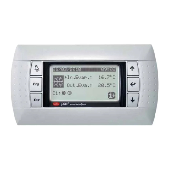
Page 5: User Interface (Pgd1)
USER INTERFACE (PGD1) Language: Language: ENGLISH Push ENTER for change ESC to con rm Time show mask: The command panel of the unit allows the rapid setting of the working parameters This window makes it possible to select the language with which the system is of the machine, and their visualisation. -
Page 6: Menu Structure
1.3 MENU STRUCTURE Icon Menu Menu function All the functions for managing the unit as well as the information about its opera- Management of the chiller parameters, standard/ tion are displayed on the unit control panel; all the functions and information are energy saving work set-point when functioning in organised into windows, which are in turn grouped in to menus. -
Page 7: User Operating Procedures
1.5 USER OPERATING PROCEDURES To check or modify the operating parameters of the unit it is necessary to use the interface of the control panel on the unit. The basic operations that the user must be capable of, for the correct use of the unit, are: —... -
Page 8: Main Display
This mask is used to display the unit's general status: 2.1 DESCRIPTION OF THE STATUS IN WHICH THE CIRCUIT CAN BE FOUND NRP 2-PIPE SYSTEM: O n / O U n i t Aermec Tue 14:29 ° 19.3 °c 40.1... -
Page 9: Pipe System
If a function is not present the folowing screen will be shown: — The actual power percentage used 3.3 INFORMATION ON DHW STORAGE R e c o v e r y s i d e A t t e n t i o n Temp.Prod Tank. -
Page 10: Information On Cooling Side Heat Exchanger
4-PIPE SYSTEM 4.3 INFORMATION ON CIRCUITS 1 - 2 C i r c u i t s 4.1 INFORMATION ON COOLING SIDE HEAT EXCHANGER Total require C o l d s i d e C o l d s i d e Circuit 1: CH + Rec S e t p o i n t... -
Page 11: Input/Output Menu
INPUT/OUTPUT MENU 5.3 INFORMATION ON STATUS OF FANS (NRP) F a n 1 5.1 INFORMATION REGARDING EXTERNAL TEMPERATURE Speed 100 % O u t d o o r t e m p . Set 12.0 bar Di 5.0 bar °C Force 5.0 bar Force... -
Page 12: Information On Defrosting Status (Nrp)
5.5 INFORMATION ON DEFROSTING STATUS (NRP) C i r c u i t 1 D e f r o s t Circuit 1 Alarms 26.7 bar Fan 88% 2.4 bar 5.4 bar Delta 0.0 LiqT 40.7°C Circuit 2 Alarms Delta 0.0 5.4 bar C i r c u i t 2 —... -
Page 13: Inputs/Outputs List - Pco Board
5.7 INPUTS/OUTPUTS LIST - PCO BOARD Digital outputs Range Master CP1(compressor) circuit 1 (CC1) CP2 (compressor) circuit 1 (CC1A) CP1 (compressor) circuit 2 (CC2) CP2 (compressor) circuit 2 (CC2A) VS1 (liquid interception solenoid valve) circuit 1 VS2 (liquid interception solenoid valve) circuit 1 NO7 (exchange) Pump 1 evaporator Serious alarm... -
Page 14: Inputs/Outputs List - Μpc Board
5.8 INPUTS/OUTPUTS LIST - ΜPC BOARD DIGITAL outputs Range Master Recovery pump 1 Recovery pump 2 CP3 circuit 1 (CC1B) CP3 circuit 2 (CC2B) VS-R (recovery solenoid valve) circuit 1 VS-R (recovery solenoid valve) circuit 2 NO7 (exchange) VS-B (battery solenoid valve) circuit 1 VS-B (battery solenoid valve) circuit 2 VS-E (evaporator solenoid valve) circuit 1 NO10... -
Page 15: On/Off Menu
ON/OFF MENU SYSTEM MENU (2 PIPES) 6.1 UNIT SWITCH-ON/OFF AND SETTINGS ON THE 7.1 VISUALISATION OF CURRENT CHILLER SETTINGS FUNCTIONING MODE (2 PIPES) P l a n t s i d e O n / O U n i t O F F t o c l o c k Plant side... -
Page 16: Enabling: By Clock
7.5 MODE SELECTION: BY CALENDAR — Displays set-point 2 (only if enabled) — Indicates the set-points for production of cold water — Indicates the set-points for production of hot water C o o l i n g / H e a t i n g 7.4 ENABLING: BY CLOCK S e l e c t C o o l / H e a t w i t h C a l e n d a r... -
Page 17: Recovery Menu (2 Pipes)
RECOVERY MENU (2 PIPES) COOL MENU (4 PIPES) C o l d s i d e WARNING: The NRP - 2-pipe unit è is set up for production of Domestic Hot Water (D.H.W.). No Anti-legionella Cycle is included. O F F t o c l o c k 8.1 RECOVERY SET-POINT DISPLAY R e c o v e r y s i d e... -
Page 18: Heat Menu (4 Pipes)
10 HEAT MENU (4 PIPES) ATTENTION: The NRP 4-pipe unit is set up for production of Domestic Hot Water (D.H.W.). H e a t s i d e t o c l o c k E x t e r n a l t e m p e r a t u r e E n a b l e : Y E S NO: the unit does not produce hot water on system side... -
Page 19: Clock Menu
11 CLOCK MENU 11.3 SETTING THE CALENDAR FUNCTION C a l e n d a r 11.1 SYSTEM TIME AND DATE SETTINGS S t a r t F i n i s h A c t i o n C l o c k 0 1 / J A N . -
Page 20: Alarm Menu
12 ALARM MENU 8 : 2 2 2 9 / 3 / 1 1 N ° 0 0 3 Every time an alarm is generated, it is saved in an area of memory called “alarms A L 7 6 H i g h t e m p . T G P log”, which contains the last 100 alarms recorded in the unit. -
Page 21: List Of Alarms
13 LIST OF ALARMS There are three types of alarm resets: — Auto: automatic, when the event causing the alarm stops, also the alarm disappears. — Semi (semi-automatic) = the alarm is automatic, but if it is triggered more than 3 times in an hour then it becomes with manual reset; —... - Page 22 Code Range Description Note Delay Reset AL62 Circuit breaker compressor 2 circuit 2 Manual AL63 Circuit breaker compressor 3 circuit 2 Manual AL64 Pressure switch BP 2 from pressure switch 180s + 3s “M48” Semi Automatic AL65 Low pressure 2 from probe Semi Automatic AL66 High pressure pressostat circuit 2...
- Page 24 SCARICA L’ULTIMA VERSIONE: DOWNLOAD THE LATEST VERSION: TÉLÉCHARGER LA DERNIÈRE VERSION: http://www.aermec.com/qrcode.asp?q=5722 http://www.aermec.com/qrcode.asp?q=5714 http://www.aermec.com/qrcode.asp?q=5718 A E R M E C S . p . A . V i a R o m a , 9 9 6 - 3 7 0 4 0 B e v i l a c q u a ( V R ) - I t a l y P h o n e + 3 9 0 4 4 2 6 3 3 1 1 1 - F a x + 3 9 0 4 4 2 9 3 5 7 7 s a l e s @ a e r m e c .
Need help?
Do you have a question about the PCO5 and is the answer not in the manual?
Questions and answers