
Related Manuals for AERMEC PGD1


Summary of Contents for AERMEC PGD1
- Page 1 T r a n s l a t i o n o f O r i g i n a l i n s t r u c t i o n s Range a/w scroll User manual CARD PCO5 - PANEL PGD1 w w w . a e r m e c . c o m...
- Page 2 All specifications are subject to change without prior notice. Although every effort has been made to ensure accuracy, Aermec shall not be held liable for any errors or...
-
Page 3: Table Of Contents
...............p. 5 condensing) ..................p. 15 Start-up procedure ................p. 5 Inputs and Outputs (pCOE Expansion for NYB/NRV) ..... p. 15 Function of the PGD1 control panel keys ........p. 5 Inputs and Outputs (pCOE Expansion for “NRB0282-0754”, Menu structure..................p. 6 NRB Large 60Hz Two-circuit) ............p. 16 User operating procedures ..............p. 7 Inputs and outputs (pCOE expansion for “Variable Primary... - Page 4 Sets the logic for the setpoint and differential in cooling mode ......................p. 22 Sets the logic for the setpoint and differential in heating mode ......................p. 22 Climatic curve configuration in cooling mode ......p. 22 Climatic curve configuration in heating mode ......p. 22 Total recovery configuration ............
-
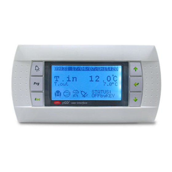
Page 5: User Interface (Pgd1)
: Pressing this key can have different functions: The installation of the remote panel PGD1 makes it possible to copy from remote all — Pressing this key when navigating menus enters the selected menu; the functions and settings available on the machine. -
Page 6: Menu Structure
1.3 MENU STRUCTURE All the functions for managing the unit as well as the information about its opera- ASSISTANCE: This menu is not accessible except by authorized staff; tion are displayed on the unit control panel; all the functions and information are organised into windows, which are in turn grouped in to menus. -
Page 7: User Operating Procedures
1.4 USER OPERATING PROCEDURES To check or modify the operating parameters of the unit it is necessary to use the interface of the control panel on the unit. The basic operations that the user must be capable of, for the correct use of the unit, are: —... -
Page 8: Main Menu
: system hot water production; — : time bands active; This mask is used to display the unit's general status: — : indicates that the low charge function is active; Aermec Fri 08:35 — : multifunction input; 9.8°C 2.3 CIRCUIT MONITORS This mask is used to display the cooling circuit's general status;... -
Page 9: Free Cooling Monitor
2.5 FREE COOLING MONITOR 2.6 GLYCOLFREE MONITOR This mask is used to display the status of the free cooling circuit: This mask is used to display the status of the glycolfree circuit: GlicoleFree Freecooling Glycol Free 0/100% Power FC: 0/100% Power FC: Total: 15.1°C... -
Page 10: Total Recovery Monitor
Di : 0.0bar general off (the whole unit is in stand-by), off from the display (general disabling of the unit from the pGD1 button); — Demand: this value indicates the actual power requested for total recovery 2: Preventil. 2: Preventil. -
Page 11: Defrosting Monitor
3.3 DEFROSTING MONITOR 3.4 MULTIFUNCTION INPUT MONITOR This window contains the information concerning the state of defrosting on the This window contains the information concerning the state of the multifunction unit: input: Plant Defrost C1 Input Multifunction Disabled (ID4 PCOE): ACTIVE High ext. -
Page 12: Input And Output
INPUT AND OUTPUT 4.1 ANALOGUE INPUTS Analogue inputs Code Range Description NRB 6 CP / NRBH 6CP Low pressure transducer circuit 2 Condensing units up to 6 CP Step switch on contact Evaporator water outlet probe Condensing units up to 6 CP Step switch on contact Multifunction Multi-function input... -
Page 13: Analogue Outputs
4.4 ANALOGUE OUTPUTS Analogue outputs Code Range Description DCP1 Modulating fans unit 1 DCP2 Modulating fans unit 2 Modulating fan group 1+2 or 3 (with 3 DCP3 ventilation groups) Circuit1 modulating fan unit that switches DCP4 off at low outdoor temperatures Circuit2 modulating fan unit that switches DCP5 off at low outdoor temperatures... -
Page 14: Inputs And Outputs (Pcoe Expansion For Nrl, Nrb(Large 50Hz),Nlc,Nyb,Nrv,Brb Heat Pumps And Two-Circuit)
4.6 INPUTS AND OUTPUTS (PCOE EXPANSION FOR NRL, NRB(LARGE 50HZ),NLC,NYB,NRV,BRB HEAT PUMPS AND TWO- CIRCUIT) Analogue inputs Code Range Description B1 (NTC) Circuit 1 Liquid temperature probe B2 (NTC) Circuit 2 Liquid temperature probe B3 (NTC) With supplementary heater Storage tank probe B4 (NTC) Digital inputs Digital outputs... -
Page 15: Inputs And Outputs (Pcoe Expansion For Motor Condensing)
4.8 INPUTS AND OUTPUTS (PCOE EXPANSION FOR MOTOR CONDENSING) Analogue inputs Percentage Range Description B1 (NTC) B2 (NTC) B3 (NTC) B4 (NTC) Digital inputs 100% Condensing units up to 4 CP Compressor or step switch on contact 100% Condensing units up to 6 CP Condensing units up to 4 CP Compressor or step switch on contact Condensing units up to 6 CP... -
Page 16: Inputs And Outputs (Pcoe Expansion For "Nrb0282-0754", Nrb Large 60Hz Two-Circuit)
4.10 INPUTS AND OUTPUTS (PCOE EXPANSION FOR “NRB0282-0754”, NRB LARGE 60HZ TWO-CIRCUIT) Analogue inputs Code Range Description Circuit 1 Liquid temperature probe B1 (NTC) SLB1 Circuit 1 liquid temperature probe coil 1 NRB Single Circuit Circuit 2 Liquid temperature probe B2 (NTC) SLB2 NRBH Single Circuit... -
Page 17: On/Off Menu
ON/OFF MENU SYSTEM MENU 5.1 GENERAL ON/OFF 6.1 SELECTING THE SYSTEM OPERATING MODE This window makes it possible to view the general state of the system as well as to This mask is used to display the current unit state, to turn the unit on or off and to turn the unit on or off: select the operating mode: On/O Unit... -
Page 18: Setting The Values For The Secondary Setpoints
6.3 SETTING THE VALUES FOR THE SECONDARY 6.5 SET THE TIME BANDS (C) AND (D) SETPOINTS This mask is used to set the times and action to assign to the time bands (c) and (d): This mask is used to set the values to assign to the secondary working setpoints: Plant Plant Timezone... -
Page 19: Setting The Season Change From The Calendar (Heating)
— general off (whole unit in stand-by); This mask is used to set the start and end date for cooling mode: — off from display (general disabling of the unit from the pGD1 button); Cooling/Heating Enable: allows to enable or disable the total recovery;... -
Page 20: Clock Menu
CLOCK MENU 8.1 SETTING SYSTEM DATE AND TIME 8.3 SETTING THE PUBLIC HOLIDAYS ON THE CALENDAR This mask is used to set the system date and time: This mask is used to set the days (up to 5 intervals) to mark as "holidays" (therefore to activate the relative time programming previously specified for the holiday time Clock band), or set the off mode for the system:... -
Page 21: Installer Menu
INSTALLER MENU 9.1 PASSWORD TO ACCESS THE INSTALLER MENU (0000) — 3: 9600 baud; — 4: 19200 baud; — 5: 38400 baud; This mask is used to enter the password necessary for accessing the installer menu Stopbits: this value indicates the number of bits used to indicate the bitstop in (the password is 0000): serial communication;... -
Page 22: Setting Thermostat Regulation
9.8 SETS THE LOGIC FOR THE SETPOINT AND Parity: indicates the actual value assigned to the number of parity bits for com- munication between the unit and the BMS2 supervision system; the values that DIFFERENTIAL IN HEATING MODE can be set are: —... -
Page 23: Total Recovery Configuration
9.11 TOTAL RECOVERY CONFIGURATION 9.13 MANAGING THE PUMPS This window allows to set the temperatures (minimum and maximum and differ- This mask is used to manage the pumps inside and outside the unit: ential) for the recovery management, in addition to the pump management logic: Installer Installer Number of Pumps:... -
Page 24: Configuration Of The Anti-Freeze Alarm On The Total Recovery
9.15 CONFIGURATION OF THE ANTI-FREEZE ALARM ON 9.18 MULTI-FUNCTION INPUT CONFIGURATION (U3) THE TOTAL RECOVERY This mask is used to set the function associated with multifunction input U3: This mask allows to set the parameters for managing the anti-freeze alarm control Installer on the total recovery: Installer... -
Page 25: Configuration Of Variable Setpoint For Input (U3)
9.20 CONFIGURATION OF VARIABLE SETPOINT FOR INPUT 9.23 CONFIGURATION OF THE SUPPLEMENTARY ELECTRIC (U3) HEATERS This mask is used to set the "VARIABLE SETPOINT" function for input U3: This mask is used to set the operation of the supplementary heaters in case of low outside temperatures: Installer Installer... -
Page 26: Compressor Hour Counter Monitor
Replacement air temp. aria: this value indicates the outside temperature below Fans which the heat pump stops and the electric heaters or, if enabled, the boiler, are used for heating; Fans 9.26 COMPRESSOR HOUR COUNTER MONITOR Start time: This window displays the data relative to the operating hours of the compressors on the unit: Minimum V: Hour meter... -
Page 27: Configuration Of The Fan Speed In Free Cooling
9.30 CONFIGURATION OF THE FAN SPEED IN FREE COOLING 9.33 VPF MANAGEMENT (GENERAL PARAMETERS) This window is used to configure the inverter fan signals during the free cooling This window is used to set the general parameters for the VPF (Variable Primary operation: Flow): Fans... -
Page 28: Vpf Management (Bypass 2 Parameters)
This window contains information concerning the unit code, the software version and the machine test date: Supervisor BMS Information STANDARD [°C/bar] Aermec S.p.A. Code: NRB0754XH°°°°°P1 Type of units of measure: indicates the units of measure shown on the display; Ver.: 2.6.071 20/06/22... -
Page 29: Alarm
10 ALARM 10.1 CONTROL OF ALARMS 15:10 Alarms 3/04/20 N°004 AL121 Warning! Only reset once. -Driver o ine If fault re-occurs call assistance! 35.0°C Active alarms: Out: 38.0°C This mask displays the alarm management logic. At any time it is possible to view the history of the last 100 alarms that have oc- Alarms with password-protected reset are: curred in the system. -
Page 30: List Of Alarms
10.3 LIST OF ALARMS Code Description Reset Note AL01 Clock battery faulty or not connected Automatic AL02 Expansion memory damaged Automatic AL03 Phase monitor Semi-Automatic AL04 Display alarm reset AL05 High pressure sensor circuit 1 faulty or not connected Manual Analog input U5 AL06 High pressure sensor circuit 2 faulty or not connected... - Page 31 Code Description Reset Note AL100 Offline pCOE expansion (address=4) condenser unit Manual AL101 Offline pCOE expansion (address=5) NYB Freecooling Manual AL102 Water input outside operating limits Manual AL103 DeltaP alarm Circuit 1 Manual AL104 DeltaP alarm Circuit 2 Manual AL105 EVD Error Valve Motor A Manual AL106...
- Page 32 SCARICA L’ULTIMA VERSIONE: DOWNLOAD THE LATEST VERSION: TÉLÉCHARGER LA DERNIÈRE VERSION: http://www.aermec.com/qrcode.asp?q=18660 http://www.aermec.com/qrcode.asp?q=18661 http://www.aermec.com/qrcode.asp?q=18663 A E R M E C S . p . A . V i a R o m a , 9 9 6 - 3 7 0 4 0 B e v i l a c q u a ( V R ) - I t a l y P h o n e + 3 9 0 4 4 2 6 3 3 1 1 1 - F a x + 3 9 0 4 4 2 9 3 5 7 7 s a l e s @ a e r m e c .
Need help?
Do you have a question about the PGD1 and is the answer not in the manual?
Questions and answers
I don't have any solution for Alarme AL131 high superheating C1
Alarm AL131 "High overheating of Circuit 1 (Circuit discharged)" on the AERMEC PGD1 indicates that Circuit 1 is experiencing excessively high superheating and has been discharged.
To resolve this:
1. Check the refrigerant charge level in Circuit 1.
2. Inspect the expansion valve operation and settings.
3. Verify the intake and discharge temperatures to ensure proper heat exchange.
4. Make sure the relevant temperature and pressure probes are functioning and connected.
5. Clear the alarm manually after addressing the issue, as it is a manual reset type.
This answer is automatically generated