
Related Manuals for AERMEC Turbocor C-Touch


Summary of Contents for AERMEC Turbocor C-Touch
- Page 1 2 2 / 0 6 – 4 4 7 1 9 2 1 _ 0 2 T r a n s l a t i o n o f O r i g i n a l i n s t r u c t i o n s Turbocor User manual CARD PCO5 - PANEL C-TOUCH...
- Page 3 All specifications are subject to change without prior notice. Although every effort has been made to ensure accuracy, Aermec shall not be held liable for any errors or...
-
Page 4: Table Of Contents
TABLE OF CONTENTS WMX/WMG/TW110 digital inputs page ........p. 18 1. Quick reference ...................p. 6 TBX digital outputs page ..............p. 18 2. Structure of the menus ..............p. 7 WTX/WTG digital outputs page ............. p. 18 Interacting with the graphic interface ...........p. 7 WMX/WMG digital outputs page ..........p. 18 Navigating between the program pages ........p. 7 TW110 digital outputs page ............ - Page 5 Sets signal management logic for multifunction input ..p. 23 Set unit of measurement for the system ........p. 23 Enable low load function ..............p. 23 Enable Freecooling ................p. 24 Freecooling Parameters ..............p. 24 Freecooling Fans .................. p. 24 Freecooling Fans + compressors ..........p. 24 Chiller protection page ..............
-
Page 6: Quick Reference
QUICK REFERENCE This manual describes all the windows found in the control software of the C-Touch referring him/her to the relative page of the manual where there is a description of panel, but the list below contains all the basic operations that the user might need, that specific function (for all other information, refer to the contents page): Switching the unit ON/OFF (4 ON/OFF menu p. 12) Selecting the operating mode (4.1 Main page p. 12) -
Page 7: Structure Of The Menus
STRUCTURE OF THE MENUS 2.2 NAVIGATING BETWEEN THE PROGRAM PAGES As already mentioned on the previous pages, the unit operating information is With the C-touch panel, the user can manage all the operating parameters of the sub-divided into various menus, each containing several pages. The basic opera- unit via a touchscreen graphic interface. -
Page 8: Setting A Numerical Value For A Parameter
2.3 SETTING A NUMERICAL VALUE FOR A PARAMETER 2.4 SETTING A VALUE, SELECTING IT FROM A LIST Many parameters (e.g. the seasonal operating set-points) require the user to enter Some parameters (e.g. selecting the setpoints to be used) provide for the user to a numerical value. -
Page 9: Main Monitor
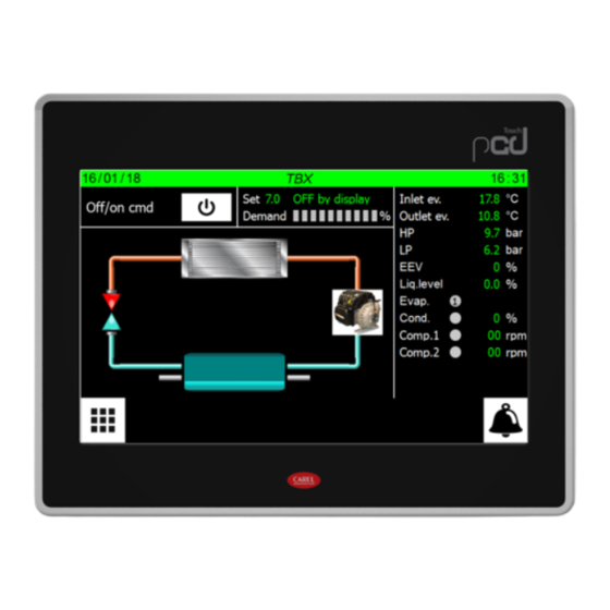
MAIN MONITOR 3.2 MAIN MONITOR - WTX/WTG This page contains general information on the current status and operation of the unit. Moreover, by pressing the graphical elements that represent the components of the cooling circuit, it is possible to enter specific sub-windows where to view the data relating to the selected component;... -
Page 10: Main Freecooling Monitor - Tba/Tbg
— Indicates the setpoint value currently set Req./MaxReq. = power level required by the compressor; — Indicates the current status of the unit. This status can be: Sp.Req. = target speed which the compressor aims at to achieve the request; WAIT = Unit waiting for control board start (5 seconds);... -
Page 11: Main Monitor - Electronic Valve Page (Not Available For Tw110)
3.6 MAIN MONITOR - ELECTRONIC VALVE PAGE (NOT — Pump inversion: change between pump 1 and pump 2 in progress; — Alarm: pump in alarm; AVAILABLE FOR TW110) — Force On: pump forced in on mode; — Not present: pump not present; 2. -
Page 12: On/Off Menu
ON/OFF MENU 4.2 TIME PERIODS PAGE - DAILY SETTING This page enables to manage the crucial commands of the uni. Through this win- dow the user can turn the machine on or off, set the values relative to the setpoints and, for the units that require it, set the seasonal operating mode. -
Page 13: Alarm Menu
ALARM MENU 5.2 DISPLAYS ALARMS LOG The ALARM menu is used to view (and reset, if necessary) the alarm conditions that may arise on the unit while it's working. The alarms are divided into various catego- ries according to their seriousness. Remember that some of them can cause serious damage to the unit so, before performing a reset, it's important to be sure about the nature of the alarm and the reason it was triggered (contacting specialised techni- cal personnel if necessary). - Page 14 Code Description Reset AL030 Turbocor2 Pressing line Gas High Temp. Manual AL031 Turbocor1 Inverter temp Auto AL032 Turbocor1 Discharge temp Auto AL033 Turbocor1 Suction pres Auto AL034 Turbocor1 Discharge pres Auto AL035 Turbocor1 Rotor Lock Auto Manual AL036 Turbocor1 Phase current Remove voltage for 30s AL037 Turbocor1 Cavity temp...
- Page 15 Code Description Reset AL102 Turbocor2 Superheat TurboAL AL103 Turbocor2 Inverter error signal TurboAL AL104 Turbocor2 AVC data missing TurboAL AL105 Turbocor2 Motor Back EMF low TurboAL AL106 Turbocor2 EEprom error TurboAL AL107 Turbocor2 Generator mode TurboAL AL108 Turbocor2 SCR phase TurboAL AL109 Turbocor2 offline...
- Page 16 Code Description Reset AL193 Turbocor4 Suction press. TurboAL AL194 Turbocor4 Discharge press. TurboAL AL195 Turbocor4 Rotor Lock TurboAL AL196 Turbocor4 Phase current TurboAL AL197 Turbocor4 Cavity temp. TurboAL AL198 Turbocor4 overcurrent TurboAL AL199 Turbocor4 Compressor ratio TurboAL AL200 Turbocor4 DC Low Voltage TurboAL AL201 Turbocor4 SCR temp.
-
Page 17: Input/Output Menu
INPUT/OUTPUT MENU 6.4 TW110 ANALOGUE INPUTS PAGE These pages contain the values and states associated with inputs and outputs avail- able on the unit. 6.1 TBX ANALOGUE INPUTS PAGE The values read by the transducers and by the probes connected to the various analogue inputs available on the unit board are indicated. -
Page 18: Wmx/Wmg/Tw110 Digital Inputs Page
6.7 WMX/WMG/TW110 DIGITAL INPUTS PAGE The statuses of the available digital outputs are indicated (green = On; grey = Off). 6.11 TW110 DIGITAL OUTPUTS PAGE The statuses of the digital inputs available on the unit board are indicated 6.8 TBX DIGITAL OUTPUTS PAGE The statuses of the available digital outputs are indicated (green = On;... -
Page 19: Diagram Menu
DIAGRAM MENU CLOCK MENU Through the GRAPHS menu it is possible to display, in real-time, the graph of the With the CLOCK menu you can set the system timer (on the pCO5+ board) and the evaporator inlet and outlet temperature probes. display timer. -
Page 20: Installer Menu
INSTALLER MENU — Used to set English as the system language — Used to set Italian as the system language — Used to set Russian as the system language The INSTALLER menu is used to access many of the settings for operating and ad- justing the unit;... -
Page 21: Selection Of The Heating Adjustment Logic (Heat Pumps Only)
9.6 SELECTION OF THE HEATING ADJUSTMENT LOGIC Set a potential power request limit of the thermostat to prevent alarm conditions or set a maximum ceiling on unit consumptions. (HEAT PUMPS ONLY) 9.9 PUMP SETTINGS (PAGE 1) — Sets the probe on which to base heating adjustment. The potential choices are: COND.INL. -
Page 22: Displays The Work Hours Status Of The Components Of The Unit (Page 2)
— Indicates the number of hours of operation for the various components (the — Sets the protocol to be used for the BMS1. The available protocols are: MODBUS; number at the top indicates the index of the component in case there are more than one on the unit): CAREL;... -
Page 23: Sets Signal Management Logic For Multifunction Input
9.19 ENABLE LOW LOAD FUNCTION NTC = signal from NTC temperature probe; — To enable the U3 multifunction input, it is required to operate on the digital input ID14. It is possible to choose the state with which to enable use of the multifunctional input: CLOSED = if ID14 is closed the U3 input open;... -
Page 24: Enable Freecooling
9.20 ENABLE FREECOOLING 9.23 FREECOOLING FANS + COMPRESSORS — Indicates that the Freecooling function is enabled or disabled — Indicates the Freecooling + compressors fan speed — Indicates the difference between the Freecooling input temperature and the — Indicates the type of Freecooling + compressors fan regulation outdoor temperature —... -
Page 25: Sets Digital Inputs Logic
9.26 SETS DIGITAL INPUTS LOGIC 4. Enables to set the power distribution between Master and Slave. With parame- ter = 0.1% the required power increases simultaneously on the Master and on the Slave. With parameter = 100.0% the required power increases first on one chiller then on the other based on the number of hours of operation. -
Page 26: Notes On Connecting Two Master/Slave Units
9.30 NOTES ON CONNECTING TWO MASTER/SLAVE UNITS MASTER unit Address Table of contents Element Unit PLAN MODBUS Display touch screen pGDTouch PCO5+ control board EEV electronic valve driver Master Driver turbocor 1 Driver turbocor 2 Plan Display touch screen pGDTouch PCO5+ control board EEV electronic valve driver Slave... - Page 28 SCARICA L’ULTIMA VERSIONE: DOWNLOAD THE LATEST VERSION: TÉLÉCHARGER LA DERNIÈRE VERSION: http://www.aermec.com/qrcode.asp?q=6159 http://www.aermec.com/qrcode.asp?q=6158 http://www.aermec.com/qrcode.asp?q=13584 A E R M E C S . p . A . V i a R o m a , 9 9 6 - 3 7 0 4 0 B e v i l a c q u a ( V R ) - I t a l y P h o n e + 3 9 0 4 4 2 6 3 3 1 1 1 - F a x + 3 9 0 4 4 2 9 3 5 7 7 s a l e s @ a e r m e c .
Need help?
Do you have a question about the Turbocor C-Touch and is the answer not in the manual?
Questions and answers