Sign In
Upload
Manuals
Brands
Advantech-DLoG Manuals
Industrial PC
DLT-V8310
User Manuals: Advantech-DLoG DLT-V8310 Computers
Manuals and User Guides for Advantech-DLoG DLT-V8310 Computers. We have
2
Advantech-DLoG DLT-V8310 Computers manuals available for free PDF download: Manual, Operating Instructions Manual
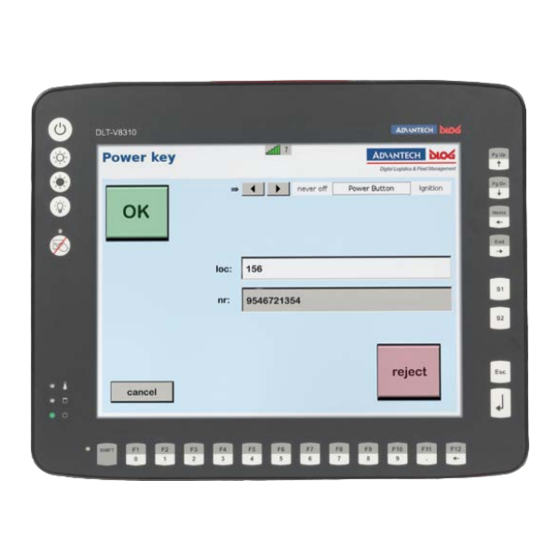
Advantech DLoG DLT-V8310 Operating Instructions Manual (157 pages)
Brand:
Advantech DLoG
| Category:
Industrial PC
| Size: 6 MB
Table of Contents
Table of Contents
3
1 Introduction
5
Information about the DLT-V83 Manuals
5
Current Manual Versions
5
Operating Instructions for All Device Models
5
Warnings and Notes in the Operating Instructions
6
2 Technical Customer Support
7
3 Functional Description
8
Intended Use
8
Mount, Operate and Service the Device Correctly
9
Device Identification / Name Plate
9
4 Unpacking, Transporting, Storing Dlt-V83
10
Unpacking
10
Transporting
10
Storage
11
5 Technical Data of the Device
12
General
12
CPU, Chipset, RAM, BIOS
12
Memory
13
Housing, Material, Weight
13
Display
13
Environmental Conditions
14
Resistive Touchscreen
15
Projected-Capacitive Touchscreen (PCT)
16
Device Dimensions
17
Fig. 5.1: Dimensions DLT-V8310
17
Fig. 5.2: Dimensions DLT-V8312
18
Fig. 5.3: Dimensions DLT-V8315
19
Internal Speaker, Sound
20
Fig. 5.4: Internal Speaker Position
20
Power Supply Units, Power Supply
21
Integrated DC Power Supply Unit
21
Fig. 5.5: DC Power Supply Connector with Connector Detail View
21
Fig. 5.6: DC Connection Cable, Original Advantech
23
Fig. 5.7: DC Connection Cable Assignment - Drawing
23
Integrated AC Power Supply Unit
24
Fig. 5.8: AC Power Connector with Detail View
24
6 Technical Data on Radio Modules
27
Identification of the Equipment Variants
27
Radio Cards
27
Available Radio Cards for WLAN
27
Available Radio Cards for WWAN
29
Antennas
30
WLAN Antenna Diversity, Low Profile IEEE 802.11 A/B/G/N
30
Fig. 6.1: WLAN Antenna IEEE 802.11 A/B/G/N and Antenna Module (Optional)
30
WLAN Antenna IEEE 802.11 A/B/G/N/Ac
31
Fig. 6.2: WLAN Antenna IEEE 802.11 A/B/G/N/Ac and Antenna Module (Optional)
31
Wlan, Wwan 3G
32
Fig. 6.3: WLAN, WWAN 3G Antenna (Optional)
32
WLAN, WWAN, LTE 4G Antenna (Multiband)
33
Fig. 6.4: DLT-V83 Rear View with WLAN, WWAN, LTE 4G Antenna (Multiband)
33
External WLAN Antenna IEEE 802.11 A/B/G/N
34
Fig. 6.5: External WLAN Antenna (Optional)
34
External WWAN Antenna 3G
35
Fig. 6.6: External 3G WWAN Antenna (Optional)
35
External WWAN Antenna 2G, 3G, 4G
36
Fig. 6.7: External WWAN Antenna (Optional)
36
Bluetooth (Optional)
37
Bluetooth Integrated: WLAN Card SPARKLAN WPEQ-261ACN
37
Micro Bluetooth Adapter (USB Stick)
37
GPS Receiver External (Optional)
38
Fig. 6.8: External GPS Receiver (Optional)
38
Fig. 6.9: Ext. GPS Receiver, Display Example During Installation
38
7 Interfaces, Connectors
39
Integrated
39
LCD Interface
39
Touch Interface
39
External
40
Serial Interfaces
40
USB, Service-USB
40
Audio Interface for Handset
40
Network Interface
40
Serial Interfaces - Functions
41
COM1 as a Voltage Source (Optional)
41
COM2 as EIA-422/485 (Optional)
41
Network Adapter (10/100/1000)
41
Fig. 7.1: RJ45 Network Port
41
CAN, Digital I/O and Second Ethernet Interface (Optional)
42
Fig. 7.2: CAN, Digital In/Out and Second Ethernet Interface
42
Fig. 7.3: Pin Assignment of CAN Interface
42
Fig. 7.4: Digital I/O Interface Pin Position
43
Serial Interface Barcode Scanners
44
Tips & Tricks
44
Fig. 7.5: Optional RJ45 Network Socket of the DLT-V83
44
Connections under the Cable Cover
45
DC Devices: Connections, Expansion Interfaces
45
Fig. 7.6: DC Device External Connections with Optional Expansion Interfaces
45
AC Devices (DLT-V8315 Only): Connections, Expansion Interfaces
46
Fig. 7.7: AC Device External Connections with Optional Expansion Interfaces
46
Connections Underneath the Antenna/Protective Cap
47
Information on Service USB, Cfast and Mini SIM Card Slot
47
Fig. 7.8: Example of Antenna, Type 4 in 1
47
Fig. 7.9: Protective Cap Examples
47
8 Open/Close Antenna (or Protective Cap)
48
Avoid Property Damage
48
Disconnecting from the Electric Power Source
48
Tools Required
48
Open/Close Protective Cap
49
Open/Close Antenna
49
WLAN Antenna IEEE 802.11 A/B/G/N
49
Fig. 8.1: WLAN Antenna Unscrewed
49
WLAN Antenna IEEE 802.11 A/B/G/N/Ac
50
Fig. 8.2: Open WLAN Antenna IEEE 802.11 A/B/G/N/Ac
50
Fig. 8.3: WLAN Antenna IEEE 802.11 A/B/G/N/Ac Opened
50
WLAN, WWAN 3G Antenna
51
Fig. 8.4: WLAN, WWAN 3G Antenna
51
Fig. 8.5: WLAN, WWAN 3G Antenna Opened
51
WLAN, WWAN Antenna (Multi-Band) LTE 4G
52
Fig. 8.6: Open WLAN, WWAN Antenna
52
Fig. 8.7: Open WLAN / WWAN Antenna
52
Fig. 8.8: WLAN, WWAN Antenna Opened
52
9 Operating the Device
54
Safety Notes for Normal Operation, Control
54
Switching the DLT-V83 On/Off
56
Operating the Touchscreen
56
Fig. 9.1: <Power> Button
56
Prevent Damage to the Touchscreen
57
Operating the Resistive Touchscreen
57
Operating the PCT Touchscreen
57
DLT-V83 Front Keys with Resistive Touchscreen
58
Overview of the Operating Elements on the Device Front
58
Fig. 9.2: Example: DLT-V8312 Version with 26 Front Keys
58
Device with 26 Front Keys
59
Device with 5 Front Keys
61
Operating States
62
DLT-V83 Front Keys with PCT Touchscreen
63
Overview of the Operating Elements on the Front Side
63
Function of the Front Keys
63
Fig. 9.3: Example: Operating Elements Front Side DLT-V8310 with PCT Touchscreen
63
Operating States
64
Software Keyboard (Optional)
65
Fig. 9.4: Software Keyboard Example
65
10 General Device Configuration
66
Operating Systems (Optional)
66
Image Compatibility of Varying Cpus
66
Linux os (Optional)
66
MS-Windows os (Optional)
67
Setting up MS-Windows
67
USB Recovery Stick
67
WES 7 and Win 7 Prof.: USB Icon in the Taskbar
67
Configuring the Front Keys, Automatic Shutdown, Etc
68
Fig. 10.1: Dlog Config Tool Main Menu, Example Win 10 Iot Enterprise
68
Automatic Shutdown
69
Functional Description
69
Sequence
69
CAN and Digital I/O Settings (Optional)
70
Fig. 10.2: Start of the IXXAT Driver Installation
70
Imanager
71
Fig. 10.3: Imanager: GPIO Bank Control
71
Protecting the Display from the Memory Effect
72
Re)Calibrating the Touchscreen
72
10.10. Erp Settings for AC Devices
73
BIOS Settings in Order to Deactivate Wakeonlan
73
MS-Windows Settings for Deactivating Wakeonlan
73
Fig. 10.4: Network Connection Properties, Advanced
73
Figure 10.5: Imanager: Network Connection Properties, Power Management
73
Power Options
74
Fig. 10.6: Network Connection Properties, Advanced
74
Figure 10.7: Imanager: Network Connection Properties, Power Management
74
Fig. 10.8: Network Connection Properties, Advanced
74
11 Wlan Configuration
75
Safety Notice
75
Differences between MS Windows and Linux
76
Preparation Work at the Factory
76
Customer-Specific Settings
77
Windows Zero Configuration (WZC)
77
Advantech WLAN Client Manager (IGX Tool)
78
11.6.1. Area of Application
78
11.6.2. after Image Reinstallation: Driver Installation
78
11.6.3. Requirements
78
11.6.4. Driver Installation Winembstd7
79
Figure 11.1: System Overview in Control Panel
79
Figure 11.2: Setup.exe for 64 Bit Operating System in the Subfolder Win7_X64
80
11.6.5. Driver Installation Win7Pro / Win 8.1 Indpro / Win 10 Iot
81
Figure 11.3: Setup.exe for 64 Bit Operating Systems Win8.1 / 10
81
Figure 11.4: IGX Driver Installation Welcome Dialog
82
Figure 11.5: IGX Driver Installation User and Company Name
82
Figure 11.6: IGX Driver Installation All Program Features
83
Figure 11.7: IGX Driver Installation Starts
83
Figure 11.8: IGX Driver Installation Windows Security
84
Figure 11.9: IGX Driver Installation Exit with Finish
84
Figure 11.10: IGX Driver Installation Perform Computer Re-Start
85
11.6.6. Start WLAN Client Manager, Login
86
Figure 11.11: WCU Icon on the Desktop
86
Figure 11.12: WCU Main Window, Admin Login
86
Figure 11.13: WCU-Administrator Login Window
87
11.6.7. WLAN Client Manager Functions
88
11.6.8. License
88
Figure 11.14: Check License
88
Figure 11.15: Info Display Via Existing License
88
11.6.9. Browse Nearby Wireless Networks
89
Figure 11.16: Browse Nearby Wireless Networks Function
89
Figure 11.17: Advanced Security Settings Dialog
90
Figure 11.18: Connection When the Network Is in Range Dialog
90
Figure 11.19: Security Settings - Network Authentication Methods
92
Figure 11.20: Security Settings - Advanced Settings (Cisco: Leap)
93
Figure 11.21: Security Settings - LEAP Properties
93
Figure 11.22: Wireless Network Properties Dialog
94
Figure 11.23: Create New Profile Dialog
94
Figure 11.24: Network Connection Is Established
95
11.6.10. Roam Management
96
Figure 11.25: General Dialog in the Roam Management Menu
96
Figure 11.26: Roaming Dialog in the Roam Management Menu
97
Figure 11.27: Roam Management - Choose Band and Channels
98
Figure 11.28: Radio Dialog in the Roam Management Menu
100
Laird Connection Manager (LCM)
101
Figure 11.29: Adapter Tab in Roam Management Menu
101
Fig. 11.30: Initial Laird Connection Manager Dialog Box
101
Fig. 11.31: LCM Configuration Tab with the Manage Profiles Button
102
Fig. 11.32: LCM Manage Profiles Dialog Box with the Admin Login Tab
102
Fig. 11.33: Entering the LCM Password: SUMMIT
102
12 Wwan Configuration
103
Safety Notice
103
Differences between MS Windows and Linux
104
Preparation Work at the Factory (DLT-V83 Delivery Status)
104
SIM Card for WWAN (Customer-Specific)
105
Configuration of Radio Card SIERRA WIRELESS MC80
105
Open Device Manager
106
Establish Internet Connection
106
Fig. 12.1: SIERRA WIRELESS MC80 - Device Manager, Sierra Wireless HSPA Modem
106
Fig. 12.2: SIERRA WIRELESS MC80 - Sierra Wireless HSPA Modem - Properties
106
Fig. 12.3: SIERRA WIRELESS MC80 - Set up a New Connection or Network
106
Fig. 12.4: SIERRA WIRELESS MC80 - Connect to the Internet
107
Fig. 12.5: SIERRA WIRELESS MC80 - Connect to the Internet - Dial-Up
107
Fig. 12.6: SIERRA WIRELESS MC80 - Telephone Number and Connection Name
107
Fig. 12.7: SIERRA WIRELESS MC80 - Network Connections - Vodafone Test Connection
108
Fig. 12.8: SIERRA WIRELESS MC80 - Dial Test Connection
108
Fig. 12.9: SIERRA WIRELESS MC80 - Function Test GSM / GNSS, Test Connection Status
108
SIERRA WIRELESS MC80 Trouble Shooting
109
Fig. 12.10: SIERRA WIRELESS MC80 - Virtual COM Ports DLT-V83 with D525 Processor
109
Fig. 12.11: SIERRA WIRELESS MC80 - Virtual COM Ports DLT-V83 with I5 Processor
110
Fig. 12.12: SIERRA WIRELESS MC80 - Virtual COM Ports DLT-V83 with Celeron Processor
110
Fig. 12.13: SIERRA WIRELESS MC80 - Test NMEA Data Flows
111
Configuration of Radio Card QUECTEL EC25
112
Establish Internet Connection
112
Fig. 12.14: QUECTEL EC25 - Set up a New Connection or Network
112
Fig. 12.15: QUECTEL EC25 - Connect to the Internet
112
Fig. 12.16: QUECTEL EC25 - Connect to the Internet - Dial-Up
113
Fig. 12.17: QUECTEL EC25 - Connect to the Internet - Telephone Number
113
Fig. 12.18: QUECTEL EC25 - Network Connections - Vodafone Test Connection
113
Fig. 12.19: QUECTEL EC25 - Dial Vodafone Test Connection
114
Fig. 12.20: QUECTEL EC25 - Function Test GSM / GNSS, Test Connection Status
114
QUECTEL EC25 Trouble Shooting
115
Fig. 12.21: QUECTEL EC25 - Virtual COM Ports DLT-V83 with I5 Processor
115
Fig. 12.22: QUECTEL EC25 - Virtual COM Ports DLT-V83 with Celeron Processor
115
Fig. 12.23: QUECTEL EC25 - Test NMEA Data Flows
117
13 Mechanical Mounting
118
Warning about Injuries and Property Damage
118
Important: Installation of the DLT-V83 on Vehicles
119
Overview of Mounting Steps
120
Connecting External Accessories to the DLT-V83
120
Attaching Device Mounting and Accessory Mounting (Optional)
121
VESA Drill Holes
121
Fig. 13.1: Position of the VESA Drill Holes DLT-V8310
121
Fig. 13.2: Position of the VESA Drill Holes DLT-V8312
122
Fig. 13.3: Position of the VESA Drill Holes DLT-V8315
123
14 Electrical Connection
124
Connection to the Power Supply
124
Connecting DC Devices to the Power Supply
125
Fig. 14.1: DC Connection Cable with Phoenix Contact Connector
125
Important: Electrical Connection of the DLT-V83 to Vehicles
126
Electrical Installation of DC Devices
126
Fig. 14.2: Position of the Ground Bolt
126
Electrically Isolated Installation of DC Devices
127
Connecting AC Devices to the Power Supply
128
Electrical Installation of AC Devices
128
15 Attaching the Cable Cover
129
Overview of Mounting Steps
129
Required Components
130
Fig. 15.1: Cable Cover with Integrated UPS Battery (Optional)
130
Fig. 15.2: Dummy Grommets and Cable Grommets for Various Cable Diameters
130
Attaching Cable Grommets and Fixing Strain Relief in Place
131
Figure 3: Cable Grommets and Dummy Grommets
131
Fig. 15.4: Example Cable Grommet
132
Fig. 15.5: the Power Supply Cable, Fit with a Cable Grommet, in the Strain Relief Rail
132
Fig. 15.6: Unused Cable Outlets Sealed off
132
Fig. 15.7: Power Supply Cable with Cable Clip on the Strain Relief Rail
133
Fig. 15.8: Detailed View Cable Clips on Strain Relief Rail
133
Fig. 15.9: Cables and Dummy Grommets
133
Attaching the Cable Cover (Without Integrated UPS)
134
Attaching the Cable Cover (with Integrated UPS)
134
Fig. 15.10: Screwing the Cable Cover into Place
134
Fig. 15.11: Cable Cover with Integrated UPS Battery
134
Pressure Compensation Element
135
Fig. 15.12: Pressure Compensation Element - Do Not Modify or Remove
135
16 Optional Equipment/Accessories
136
Integrated UPS (Optional)
136
Fig. 16.1: Cable Cover with Integrated Battery Packs for the UPS
136
UPS Battery Pack Specification
137
Charging the Integrated UPS Correctly
138
No Repair/Replacement of the Battery Packs
138
Screen-Defroster (Optional)
138
Pre-Converter and Power Cables (Optional)
139
Voice Kit (Optional)
139
Fig. 16.2: Voice Kit Microphone (Optional)
139
Terminal Mountings (Optional)
140
Keyboards and Keyboard Holders (Optional)
140
Fig. 16.3: Mounting Bracket and RAM-Mount Solution
140
Fig. 16.4: SMALL Keyboard and 24-Key Keypad
140
Fig. 16.5: Keyboard Mounting Holder Examples
140
Stylus for Touchscreens (Optional)
141
External CD/DVD-ROM Drive (Optional)
141
Fig. 16.6: Stylus Examples
141
USB Recovery Stick (Optional)
142
Scanner and Scanner Bracket (Optional)
142
Sun Visor (Optional)
142
Protective Film for Touchscreen (Optional)
142
Fig. 16.7: DLT-V8312 with Sun Visor
142
17 Maintenance, Cleaning
143
Manufacturer, Authorized Service Centers
143
No Repair/Replacement of the Battery Packs
143
17.3. Regular Checks and Maintenance of the Complete System
143
Cleaning the Device
144
Cleaning the Housing
144
Cleaning the Touchscreen
144
Touchscreen Protective Film (Optional)
145
18 Malfunctions
146
19 Reasonably Foreseeable Misuse
148
General
148
Mobile Application on Vehicles
148
Stationary Use with AC Power Supply Unit
148
20 Guidelines and Certificates
149
Simplified EU Declaration of Conformity
149
Low-Voltage Guidelines
149
EMC Guidelines
149
Shielded Components
149
Emc Eu
149
Fcc Usa
149
ICES Canada
150
Rohs Directive EU
150
RED (Radio Equipment Directive) 2014/53/EU
151
Eco-Design Directive (2009/125/EC)
152
CE Marking
152
CCC, SRRC China
152
Cnrohs
153
MIC Japan (Previously TELEC)
153
21 Recycling Information
154
22. List of Figures
155
22 List of Figures
155
Advertisement
Advantech-DLoG DLT-V8310 Manual (178 pages)
DLT-V83 Series
Brand:
Advantech-DLoG
| Category:
Industrial PC
| Size: 6 MB
Table of Contents
Table of Contents
5
1 Important Information about the Dlt-V83 Manuals
7
Available Manuals (in Printed Form or on the Internet)
8
Current Manuals and Drivers on the Internet
8
Design Elements in the Manual
9
Signal Words for Indicating Risk Level
9
Information about Physical Damage, Tips
9
ONE Manual for All Device Models
10
2 Essential Safety Instructions
11
Installation/Commissioning by Qualified Skilled Personnel
12
User Training Required
12
Hazards from Lithium-Ion Batteries
13
Proper Storage
14
Charging Correctly
14
Risks During Installation/Commissioning
15
Risks During Handling/Running Operation
15
No Repair/Replacement of the Lithium-Ion Batteries
15
Hazards from Electric Power
16
Hazards During Transport, Installation, and Commissioning
19
Observe When Connecting/Removing External Devices
20
Radio Wave Emission Hazards
21
Do Not Repair or Modify
22
3 Functional Description
23
Intended Use
24
Requirements for Safe Operation
24
Permitted Environmental Conditions
24
Mount, Operate and Service the Device Correctly
25
Warranty Conditions
25
LCD Display
25
Device Identification/Name Plate
26
Fig. 3.1: Name Plate, Example
26
4 Unpacking, Transporting and Storing the Device
27
Unpacking
28
Transport
28
Storage
28
Protecting Touchscreens from Damage
28
Device with Integrated UPS and Lithium-Ion Batteries
28
If a Return/Repacking Is Necessary
30
5 Operating the Touchscreen, Front Keys
31
Switching the DLT-V83 On/Off
32
Fig. 5.1: <Power> Button of the DLT-V83
32
Configuration
32
Operating the Touchscreen
33
Prevent Damage to the Touchscreen
33
Operating the Resistive Touchscreen
33
Operating the PCT Touchscreen
34
DLT-V83 Front Keys with Resistive Touchscreen
35
Overview of the Operating Elements on the Device Front
35
Fig. 5.2: Operating Elements on the DLT-V8310, 26 Front Keys, Resistive Touchscreen
35
Device with 26 Front Keys
36
Device with 5 Front Keys
38
Operating States
39
DLT-V83 Front Keys with PCT Touchscreen
40
Overview of the Operating Elements on the Front Side
40
Fig. 5.3: Operating Elements Front Side DLT-V8310 with PCT Touchscreen
40
Function of the Front Keys
41
Operating States
42
Software Keyboard (Optional)
43
Fig. 5.4: Software Keyboard
43
6 Configuration
44
Configuring the DLT-V83 with Linux (Optional)
45
MS Windows Operating Systems (Optional)
45
Setting up MS Windows
45
USB Recovery Stick
45
WES 7 and Win 7 Prof.: USB Icon in the Taskbar
45
Configuring the Front Keys, Automatic Shut Down, Etc
46
Fig. 6.1: Dlog Config Tool Main Menu
46
Wi-Fi (Optional)
47
Wireless Performance
47
Antenna Solutions for Use in Germany
48
Wi-Fi Configuration with SCU, LCM or WZC
48
Summit Client Utility (SCU) for Wi-Fi Configuration
49
Fig. 6.2: Summit Client Utility Menu
49
Laird Connection Manager (LCM)
50
Fig. 6.3: Initial Laird Connection Manager Dialog Box
50
Fig. 6.4: LCM Configuration Tab with the Manage Profiles Button
50
Windows Zero Configuration (WZC)
51
Fig. 6.5: LCM Manage Profiles Dialog Box with the Admin Login Tab
51
Fig. 6.6: Entering the LCM Password: SUMMIT
51
WWAN, Internal GPS (Optional)
52
Mini SIM Card for WWAN Operation
52
Installation, Configuration, Test
53
Fig. 6.7: WWAN Driver Installation, Sierra Wireless Driver to C:\Util
53
Fig. 6.8: WWAN Driver Installation, WWAN 32-Bit
54
Fig. 6.9: WWAN Driver Installation, Run as Administrator
54
Fig. 6.10: WWAN Driver Installation, COM Port
55
Fig. 6.11: Driver Configuration, Open Device Manager
56
Fig. 6.12: Driver Configuration, Sierra Wireless Card Using Vodafone as Example
56
Fig. 6.13: Function Test GSM / GPS, Network and Sharing Center
57
Fig. 6.14: Function Test GSM / GPS, Connect to the Internet
58
Fig. 6.15: Function Test GSM / GPS, Wireless
58
Fig. 6.16: Function Test GSM / GPS, Telephone Number
59
Fig. 6.17: Function Test GSM / GPS, Network Connections
59
Fig. 6.18: Function Test GSM / GPS, Test Connection
60
Fig. 6.19: Function Test GSM / GPS, Test Connection Status
60
Fig. 6.20: Deleting the GPS Test Connection
61
Fig. 6.21: GPS Test
61
Fig. 6.22: GPS Test, COM4
62
Fig. 6.23: GPS Test Position Data
62
External GPS Solution (Optional)
63
Fig. 6.24: GPS Receiver (Optional)
63
Fig. 6.25: Ext. GPS Receiver, Display Example During Installation
63
CAN and Digital I/O Settings (Optional)
64
Fig. 6.26: Start of the IXXAT Driver Installation
64
Imanager
65
Fig. 6.27: Imanager: GPIO Bank Control
65
Configuring Screen Blanking (Optional)
66
Protecting the Display from the Memory Effect
66
Re)Calibrating the Touchscreen
66
Erp Settings for AC Devices
67
BIOS Settings in Order to Deactivate Wakeonlan
67
Windows Settings for Deactivating Wakeonlan
67
Fig. 6.28: Network Connection Properties, Advanced
67
Figure 6.29: Imanager: Network Connection Properties, Power Management
67
Power Options
68
Fig. 6.30: Network Connection Properties, Advanced
68
Figure 6.31: Imanager: Network Connection Properties, Power Management
68
Fig. 6.32: Network Connection Properties, Advanced
68
7 Mounting (Mechanical and Electrical)
69
Warning about Injuries and Physical Damage
70
Overview of Mounting Steps
71
Suitable Mounting Position
71
On Vehicles: Do Not Restrict Field of View
71
Observe the Minimum Distance to the Antenna
71
Installation: Cooling by Means of Fresh Air Supply
72
Connecting External Accessories to the DLT-V83
72
Attaching the Device Mounting Bracket (Optional)
73
Connecting DC Devices to the Power Supply
74
Fig. 7.1: DC Connection Cable with Phoenix Contact Connector
74
Essential Information for Vehicle Applications (E.g. Forklift)
75
Electrical Installation
75
Electrically Isolated Installation
76
Fig. 7.2: Position of the Ground Bolt
76
Connecting AC Devices to the Power Supply
77
Electrical Installation of AC Devices
77
Fig. 7.3: Angled AC Power Cable
77
Attaching the Cable Cover
79
Overview of Mounting Steps
79
Required Components
80
Fig. 7.4: Cable Cover with Integrated UPS Battery (Optional)
80
Fig. 7.5: Dummy Grommets and Cable Grommets for Various Cable Diameters
80
Attaching Cable Grommets and Fixing Strain Relief in Place
81
Figure 6: Cable Grommets and Dummy Grommets
81
Fig. 7.7: Example Cable Grommet
82
Fig. 7.8: the Power Supply Cable, Fit with a Cable Grommet, in the Strain Relief Rail
82
Fig. 7.9: Unused Cable Outlets Sealed off
83
Fig. 7.10: Power Supply Cable with Cable Clip on the Strain Relief Rail
83
Fig. 7.11: Detailed View Cable Clips on Strain Relief Rail
83
Fig. 7.12: Cables and Dummy Grommets
84
Attaching the Cable Cover (Without Integrated UPS)
85
Fig. 7.13: Screwing the Cable Cover into Place
85
Attaching the Cable Cover (with Integrated UPS)
86
Fig. 7.14: Cable Cover with Integrated UPS Battery
86
Pressure Compensation Element
87
Fig. 7.15: Pressure Compensation Element - Do Not Modify or Remove
87
8 Power Supply Units, Pin Assignment, Power Supply
88
Integrated DC Power Supply Unit
89
DC Voltage Supply Connection
89
Fig. 8.1: DC Power Supply Connector with Connector Detail View
89
Connections
91
Fig. 8.2: External Connections 12/24/48 VDC Devices Detail View
91
DC Connection Cable (Power Supply Cable)
92
Fig. 8.3: DC Connection Cable, Original Advantech-Dlog
92
Fig. 8.4: DC Connection Cable Assignment - Drawing
93
Integrated AC Power Supply Unit
94
AC Power Supply Connection
94
Fig. 8.5: AC Power Connector with Detail View
94
AC Power Supply, Power Consumption
95
AC Power Supply Unit Fuses
95
Measurement Results of the Power Consumption
96
Special Connection Cable for AC Device
96
Connections, Expansion Interfaces
97
Fig. 8.6: AC Device External Connections, Detail View
97
Angled AC Power Cable
98
Fig. 8.7: Angled AC Power Cable, Original Advantech-Dlog
98
9 Service Usb and Sim Card Slot
99
Opening/Closing the Service USB and SIM Card Slot
100
Fig. 9.1: Opened Antenna Cap
100
Removing/Attaching the Antenna Cap From/To the Device
101
Service USB Interface
102
Micro Bluetooth Adapter and Service USB
102
Fig. 9.2: Service USB under the Antenna Cap
102
SIM Card Slot
103
Fig. 9.3: Opened SIM Card Slot under the Antenna Cap
103
10 Optional Equipment/Accessories
104
Defroster (Optional)
105
Integrated UPS (Optional)
106
Fig. 10.1: Cable Cover with Integrated Lithium-Ion Battery for the UPS
106
Integrated Power Supply Unit (Optional)
107
Pre-Converter and Power Cables (Optional)
107
Integrated Low Profile Wi-Fi Antenna (Optional)
108
Fig. 10.2: Integrated Low Profile Wi-Fi Antenna (Optional)
108
Integrated Wi-Fi Antenna (Optional)
109
Fig. 10.3: Integrated Wi-Fi Antenna (Optional)
109
Integrated Wi-Fi, WWAN, and GPS Antenna (Optional)
110
Fig. 10.4: Integrated Wi-Fi, WWAN, and GPS Antenna (Optional)
110
External Wi-Fi Antenna, Remote (Optional)
111
Fig. 10.5: Remote Wi-Fi Antenna (Optional)
111
External WWAN Antenna, Remote (Optional)
112
Fig. 10.6: Remote WWAN Antenna (Optional)
112
Wi-Fi Card (Optional)
113
WWAN Card (Optional)
113
Micro Bluetooth Adapter (Optional)
114
GPS Receiver (Optional)
115
Fig. 10.7: GPS Receiver (Optional)
115
Voice Kit (Optional)
116
Fig. 10.8: Voice Kit Microphone (Optional)
116
Keyboards and Keyboard Mounts (Optional)
117
Fig. 10.9: SMALL Keyboard
117
Fig. 10.10: 24-Key Keypad
117
Fig. 10.11: Keyboard Mounting Bracket Examples
117
External CD/DVD-ROM Drive (Optional)
118
USB Recovery Stick (Optional)
118
Scanner and Scanner Bracket (Optional)
118
Serial Interfaces
118
Sun Visor (Optional)
119
Fig. 10.12: DLT-V83 with Sun Visor
119
Protective Film for Touchscreen (Optional)
120
11 Serial Interfaces
121
COM1 as a Voltage Source (Optional)
122
COM2 as EIA-422/485 (Optional)
122
Network Adapter (10/100/1000)
123
Fig. 11.1: RJ45 Network Port
123
CAN, Digital I/O and Second Ethernet Interface (Optional)
124
CAN Interface
124
Fig. 11.2: CAN, Digital In/Out and Second Ethernet Interface
124
Fig. 11.3: Pin Assignment of CAN Interface
124
Digital I/O Interface
125
Fig. 11.4: Digital I/O Interface Pin Position
125
Network Adapter 2, Ethernet (10/100/1000)
126
Fig. 11.5: Optional RJ45 Network Socket of the DLT-V83
126
Serial Interface Barcode Scanners
127
Tips & Tricks
127
12 Automatic Shut down
128
Functional Description
129
Sequence
129
Configuration
130
13 Cleaning the Device
131
Cleaning the Housing
132
Cleaning the Touchscreen
133
14 Technical Data
134
CPU, Chipset, RAM, BIOS, Cfast, SSD
135
Housing, Material, Weight
135
Display
136
Malfunctions
136
Environmental Conditions
137
DLT-V83 Without Integrated UPS
137
DLT-V83 with Integrated UPS (Optional)
137
Resistive Touchscreen
138
Standard Version
138
Version Suitable for Use in Sunlight (Optional)
139
Projected-Capacitive Touchscreen (PCT)
139
Operating Systems (Optional)
140
Serial Interfaces
140
USB, Service-USB
140
14.10. LCD Interface
141
14.11. Touch Interface
141
14.12. Network Interface
141
14.13. Audio Interface for Handset
141
14.14. Internal Speaker, Sound
142
Integrated UPS (Optional)
142
Fig. 14.1: Internal Speaker
142
14.16. Device Dimensions
143
14.16.1. Dlt-V8310
143
Fig. 14.2: Dimensions DLT-V8310 Front Side
143
Fig. 14.3: Dimensions DLT-V8310 with Standard Resistive Touchscreen, Side View
144
Fig. 14.4: Dimensions DLT-V8310 Standard Resistive Touchscreen, Top View
145
14.16.2. Dlt-V8312
146
Fig. 14.5: Dimensions DLT-V8312 Front View
146
Fig. 14.6: Dimensions DLT-V8312 Standard Resistive Touchscreen, Side View
147
Fig. 14.7: Dimensions DLT-V8312 Top View
148
14.16.3. Dlt-V8315
149
Fig. 14.8: Dimensions DLT-V8315 Front Side
149
Fig. 14.9: Dimensions DLT-V8315 Side View (Standard Resisitive Touchscreen)
150
Fig. 14.10: Dimensions DLT-V8315 Top View (Standard Resisitive Touchscreen)
151
14.17. VESA Drill Holes
152
14.17.1. Dlt-V8310
152
Fig. 14.11: Position of the VESA Drill Holes DLT-V8310
152
14.17.2. Dlt-V8312
153
Fig. 14.12: Position of the VESA Drill Holes DLT-V8312
153
14.17.3. Dlt-V8315
154
Fig. 14.13: Position of the VESA Drill Holes DLT-V8315
154
15 Malfunctions
155
General
155
WWAN Error Codes
155
16 Reasonably Foreseeable Misuse
156
General
156
Mobile Application on Vehicles
156
Stationary Use with AC Power Supply Unit
156
17 Guidelines and Certificates
157
Low-Voltage Guidelines
158
EMC Guidelines
158
Shielded Components
158
Emc Eu
158
Fcc Usa
158
ICES Canada
159
Rohs Directive
159
R&TTE EC Directive 1999/5/EC
160
Ecodesign Directive (2009/125/EC)
161
CE Marking
162
CCC, SRRC China
162
MIC Japan (Previously TELEC)
162
Fig. 17.1: CE Label on the DLT-V83
162
Declaration of Conformity
163
18 End-Of-Life Device Disposal
164
19 Technical Customer Support
164
20 Return Shipment Form
165
21 Table of Figures
166
22 Index
168
Advertisement
Related Products
Advantech-DLoG DLT-V8312
Advantech-DLoG DLT-V8315
Advantech DLoG DLT-V83 Series
Advantech-DLoG DLT-V6210
Advantech-DLoG DLT-V72 Series
Advantech-DLoG DLT-V6210FL
Advantech-DLoG DLT-V7210KD
Advantech-DLoG DLT-V7210R
Advantech-DLoG DLT-V7210D
Advantech-DLoG DLT-V7212D
Advantech-DLoG Categories
Industrial PC
Touch terminals
Desktop
Monitor
Racks & Stands
More Advantech-DLoG Manuals
Login
Sign In
OR
Sign in with Facebook
Sign in with Google
Upload manual
Upload from disk
Upload from URL